2004 DODGE TOWN AND COUNTRY spark plugs replace
[x] Cancel search: spark plugs replacePage 1403 of 2585

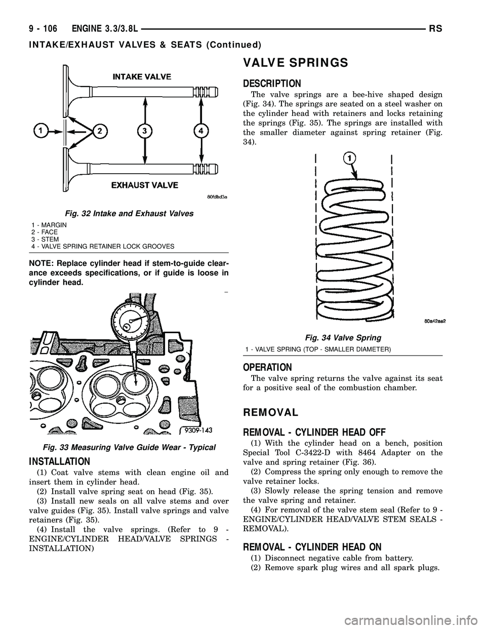
NOTE: Replace cylinder head if stem-to-guide clear-
ance exceeds specifications, or if guide is loose in
cylinder head.
INSTALLATION
(1) Coat valve stems with clean engine oil and
insert them in cylinder head.
(2) Install valve spring seat on head (Fig. 35).
(3) Install new seals on all valve stems and over
valve guides (Fig. 35). Install valve springs and valve
retainers (Fig. 35).
(4) Install the valve springs. (Refer to 9 -
ENGINE/CYLINDER HEAD/VALVE SPRINGS -
INSTALLATION)
VALVE SPRINGS
DESCRIPTION
The valve springs are a bee-hive shaped design
(Fig. 34). The springs are seated on a steel washer on
the cylinder head with retainers and locks retaining
the springs (Fig. 35). The springs are installed with
the smaller diameter against spring retainer (Fig.
34).
OPERATION
The valve spring returns the valve against its seat
for a positive seal of the combustion chamber.
REMOVAL
REMOVAL - CYLINDER HEAD OFF
(1) With the cylinder head on a bench, position
Special Tool C-3422-D with 8464 Adapter on the
valve and spring retainer (Fig. 36).
(2) Compress the spring only enough to remove the
valve retainer locks.
(3) Slowly release the spring tension and remove
the valve spring and retainer.
(4) For removal of the valve stem seal (Refer to 9 -
ENGINE/CYLINDER HEAD/VALVE STEM SEALS -
REMOVAL).
REMOVAL - CYLINDER HEAD ON
(1) Disconnect negative cable from battery.
(2) Remove spark plug wires and all spark plugs.
Fig. 32 Intake and Exhaust Valves
1 - MARGIN
2-FACE
3 - STEM
4 - VALVE SPRING RETAINER LOCK GROOVES
Fig. 33 Measuring Valve Guide Wear - Typical
Fig. 34 Valve Spring
1 - VALVE SPRING (TOP - SMALLER DIAMETER)
9 - 106 ENGINE 3.3/3.8LRS
INTAKE/EXHAUST VALVES & SEATS (Continued)
Page 1405 of 2585

(11) Repeat procedure for each cylinder requiring
valve spring removal.
INSPECTION
Whenever valves have been removed for inspection,
reconditioning or replacement, valve springs should
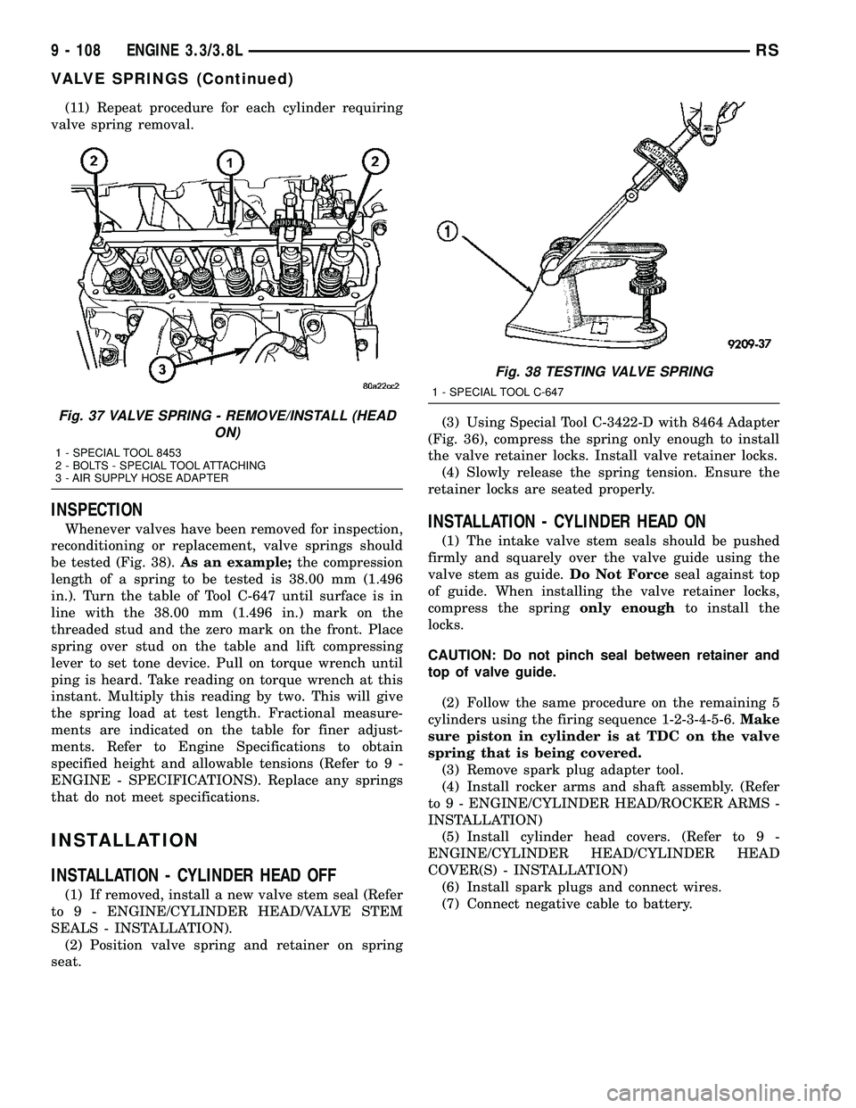
be tested (Fig. 38).As an example;the compression
length of a spring to be tested is 38.00 mm (1.496
in.). Turn the table of Tool C-647 until surface is in
line with the 38.00 mm (1.496 in.) mark on the
threaded stud and the zero mark on the front. Place
spring over stud on the table and lift compressing
lever to set tone device. Pull on torque wrench until
ping is heard. Take reading on torque wrench at this
instant. Multiply this reading by two. This will give
the spring load at test length. Fractional measure-
ments are indicated on the table for finer adjust-
ments. Refer to Engine Specifications to obtain
specified height and allowable tensions (Refer to 9 -
ENGINE - SPECIFICATIONS). Replace any springs
that do not meet specifications.
INSTALLATION
INSTALLATION - CYLINDER HEAD OFF
(1) If removed, install a new valve stem seal (Refer
to 9 - ENGINE/CYLINDER HEAD/VALVE STEM
SEALS - INSTALLATION).
(2) Position valve spring and retainer on spring
seat.(3) Using Special Tool C-3422-D with 8464 Adapter
(Fig. 36), compress the spring only enough to install
the valve retainer locks. Install valve retainer locks.
(4) Slowly release the spring tension. Ensure the
retainer locks are seated properly.
INSTALLATION - CYLINDER HEAD ON
(1) The intake valve stem seals should be pushed
firmly and squarely over the valve guide using the
valve stem as guide.Do Not Forceseal against top
of guide. When installing the valve retainer locks,
compress the springonly enoughto install the
locks.
CAUTION: Do not pinch seal between retainer and
top of valve guide.
(2) Follow the same procedure on the remaining 5
cylinders using the firing sequence 1-2-3-4-5-6.Make
sure piston in cylinder is at TDC on the valve
spring that is being covered.
(3) Remove spark plug adapter tool.
(4) Install rocker arms and shaft assembly. (Refer
to 9 - ENGINE/CYLINDER HEAD/ROCKER ARMS -
INSTALLATION)
(5) Install cylinder head covers. (Refer to 9 -
ENGINE/CYLINDER HEAD/CYLINDER HEAD
COVER(S) - INSTALLATION)
(6) Install spark plugs and connect wires.
(7) Connect negative cable to battery.
Fig. 37 VALVE SPRING - REMOVE/INSTALL (HEAD
ON)
1 - SPECIAL TOOL 8453
2 - BOLTS - SPECIAL TOOL ATTACHING
3 - AIR SUPPLY HOSE ADAPTER
Fig. 38 TESTING VALVE SPRING
1 - SPECIAL TOOL C-647
9 - 108 ENGINE 3.3/3.8LRS
VALVE SPRINGS (Continued)
Page 1474 of 2585

(10) Install the exhaust manifolds. (Refer to 9 -
ENGINE/MANIFOLDS/EXHAUST MANIFOLD -
INSTALLATION)
(11) Install new O-ring on dipstick tube. Install
dipstick tube assembly (Fig. 2).
(12) Install the spark plugs.
(13) Install upper and lower intake manifolds.
(Refer to 9 - ENGINE/MANIFOLDS/INTAKE MANI-
FOLD - INSTALLATION)
(14) Fill the cooling system. (Refer to 7 - COOL-
ING - STANDARD PROCEDURE)
(15) Connect negative cable to battery.
CYLINDER HEAD COVER(S)
DESCRIPTION
The cylinder head covers are made of stamped
steel. The covers are sealed with steel reinforced sil-
icon rubber gaskets. The cylinder head cover uses
rubber isolators at each fastener location (Fig. 7).
NOTE: Due to the tight packaging near the cylinder
head covers, which makes spill clean-up difficult, a
spill during an engine oil change may be misinter-
preted as an oil leak. When investigating an oil leak
in the location of the cylinder head covers and
intake manifold, follow the procedure found in Oil
Leak Diagnosis (Refer to 9 - ENGINE - DIAGNOSIS
AND TESTING) for determining the source of a leak.
CYLINDER HEAD COVER-
RIGHT
REMOVAL
(1) Disconnect negative cable from battery.
(2) Remove the wiper module. (Refer to 8 - ELEC-
TRICAL/WIPERS/WASHERS/WIPER MODULE -
REMOVAL)
(3) Disconnect spark plug wires from plugs.
(4) Disconnect PCV hose from cylinder head cover
(Fig. 8).
(5) Remove cylinder head cover bolts.
(6) Remove cylinder head cover and gasket (Fig.
7).
INSTALLATION
(1) Clean cylinder head and cover mating surfaces.
Inspect cylinder head cover surface for flatness.
Replace gasket as necessary.
(2) Inspect seal on the cover bolt for wear or dam-
age (Fig. 9). Replace bolt assembly as necessary.
NOTE: The cylinder head cover bolts contain a
torque limiter sleeve and a seal (Fig. 9). The seal
and torque sleeve is replaced with the bolt.
Fig. 7 Cylinder Head Cover
1 - CYLINDER HEAD COVER
2 - BOLT
Fig. 8 PCV Hose
1 - HOSE - PCV
2 - P C V VA LV E
RSENGINE 3.3/3.8L SUPPLEMENT9s-19
CYLINDER HEAD (Continued)
Page 1475 of 2585

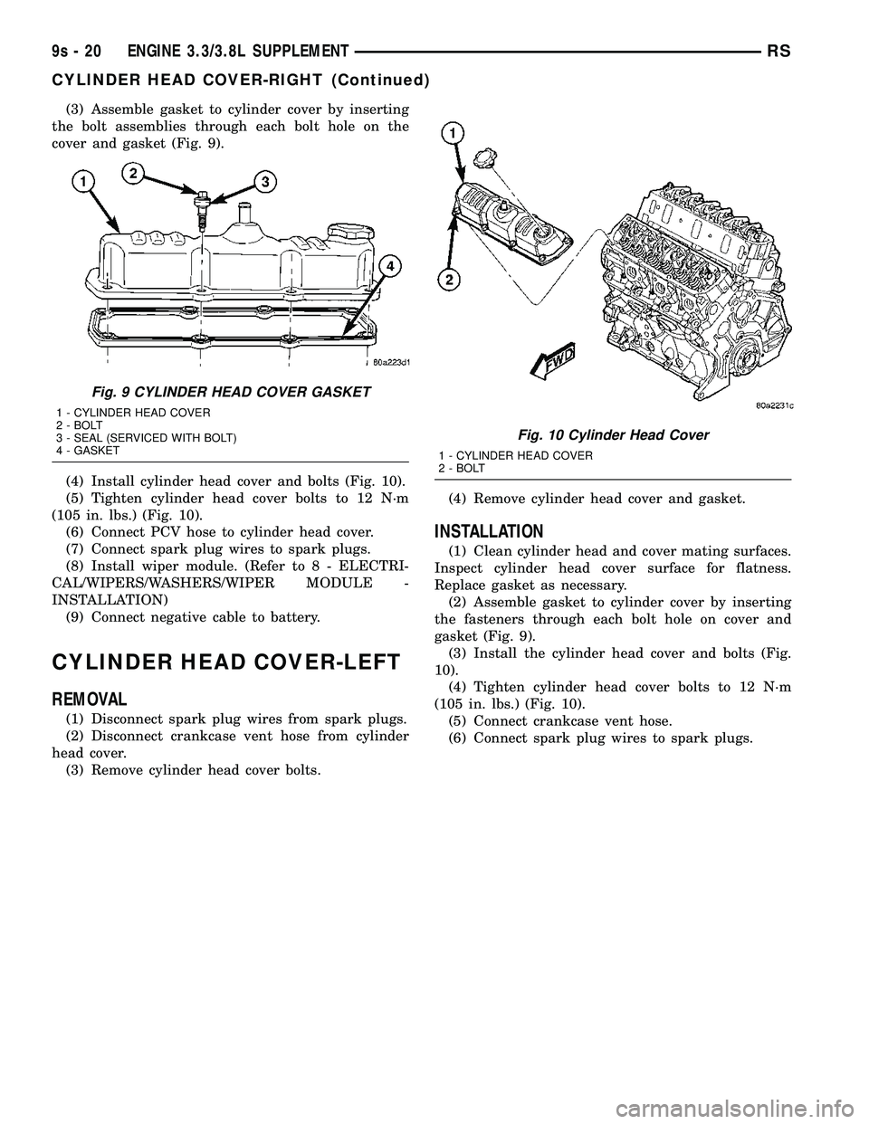
(3) Assemble gasket to cylinder cover by inserting
the bolt assemblies through each bolt hole on the
cover and gasket (Fig. 9).
(4) Install cylinder head cover and bolts (Fig. 10).
(5) Tighten cylinder head cover bolts to 12 N´m
(105 in. lbs.) (Fig. 10).
(6) Connect PCV hose to cylinder head cover.
(7) Connect spark plug wires to spark plugs.
(8) Install wiper module. (Refer to 8 - ELECTRI-
CAL/WIPERS/WASHERS/WIPER MODULE -
INSTALLATION)
(9) Connect negative cable to battery.
CYLINDER HEAD COVER-LEFT
REMOVAL
(1) Disconnect spark plug wires from spark plugs.
(2) Disconnect crankcase vent hose from cylinder
head cover.
(3) Remove cylinder head cover bolts.(4) Remove cylinder head cover and gasket.
INSTALLATION
(1) Clean cylinder head and cover mating surfaces.
Inspect cylinder head cover surface for flatness.
Replace gasket as necessary.
(2) Assemble gasket to cylinder cover by inserting
the fasteners through each bolt hole on cover and
gasket (Fig. 9).
(3) Install the cylinder head cover and bolts (Fig.
10).
(4) Tighten cylinder head cover bolts to 12 N´m
(105 in. lbs.) (Fig. 10).
(5) Connect crankcase vent hose.
(6) Connect spark plug wires to spark plugs.
Fig. 9 CYLINDER HEAD COVER GASKET
1 - CYLINDER HEAD COVER
2 - BOLT
3 - SEAL (SERVICED WITH BOLT)
4 - GASKET
Fig. 10 Cylinder Head Cover
1 - CYLINDER HEAD COVER
2 - BOLT
9s - 20 ENGINE 3.3/3.8L SUPPLEMENTRS
CYLINDER HEAD COVER-RIGHT (Continued)
Page 1490 of 2585

The combustion reaction caused by the catalyst
releases additional heat in the exhaust system, caus-
ing temperature increases in the area of the reactor
under severe operating conditions. Such conditions
can exist when the engine misfires or otherwise does
not operate at peak efficiency.Do notremove spark
plug wires from plugs or by any other means short
out cylinders, if exhaust system is equipped with a
catalytic converter. Failure of the catalytic converter
can occur due to temperature increases caused by
unburned fuel passing through the converter. This
deterioration of the catalyst core can result in exces-
sively high emission levels, noise complaints, and
exhaust restrictions.
Unleaded gasoline must be used to avoid ruining
the catalyst core. Do not allow engine to operate
above 1200 RPM in neutral for extended periods over
5 minutes. This condition may result in excessive
exhaust system/floor pan temperatures because of no
air movement under the vehicle.
The flex joint allows flexing as the engine moves,
preventing breakage that could occur from the back-
and-forth motion of a transverse mounted engine.
CAUTION: Due to exterior physical similarities of
some catalytic converters with pipe assemblies,
extreme care should be taken with replacement
parts. There are internal converter differences
required in some parts of the country (particularly
vehicles built for States with strict emission
requirements) and between model years.
REMOVAL
(1) Loosen clamp and disconnect the muffler/reso-
nator assembly from catalytic converter pipe.
(2) Disconnect downstream oxygen sensor electri-
cal connector (Fig. 4). For removal of downstream
oxygen sensor, (Refer to 14 - FUEL SYSTEM/FUEL
INJECTION/O2 SENSOR - REMOVAL).
(3) Remove catalytic converter to exhaust manifold
attaching fasteners (Fig. 5).
(4) Remove catalytic converter and gasket (Fig. 5).
INSPECTION
WARNING: THE NORMAL OPERATING TEMPERA-
TURE OF THE EXHAUST SYSTEM IS VERY HIGH.
THEREFORE, NEVER ATTEMPT TO SERVICE ANY
PART OF THE EXHAUST SYSTEM UNTIL IT IS
COOLED. SPECIAL CARE SHOULD BE TAKEN
WHEN WORKING NEAR THE CATALYTIC CON-
VERTER. THE TEMPERATURE OF THE CONVERTER
RISES TO A HIGH LEVEL AFTER A SHORT PERIOD
OF ENGINE OPERATION TIME.Check catalytic converter for a flow restriction.
(Refer to 11 - EXHAUST SYSTEM - DIAGNOSIS
AND TESTING) Exhaust System Restriction Check
for procedure.
Fig. 4 Downstream Oxygen Sensor
1 - OXYGEN SENSOR CONNECTOR
2 - CATALYTIC CONVERTER
3 - DOWNSTREAM OXYGEN SENSOR
4 - ENGINE HARNESS CONNECTOR
Fig. 5 Catalytic Converter to Exhaust Manifold
1 - FLAG NUT
2 - GASKET
3 - BOLT
4 - CATALYTIC CONVERTER
RSEXHAUST SYSTEM11-5
CATALYTIC CONVERTER (Continued)