2004 DODGE TOWN AND COUNTRY seat adjustment
[x] Cancel search: seat adjustmentPage 1798 of 2585
PRELOAD ADJUSTMENT W/O SHIM
(1) Remove the bearing cup from the differential
bearing retainer using Miller special Tool 6062A.
(2) Remove existing shim from under bearing cup.
(3) Reinstall the bearing cup into the retainer
using Miller Special Tool 6061, and C-4171.
NOTE: Oil baffle is not required when making the
shim calculation.
(4) Install the bearing retainer into the case.
Torque bolts to 28 N´m (250 in. lbs.).
(5) Position the transaxle assembly vertically on
the support stand and install Miller Special Tool
L-4436-A into the bearing retainer.
(6) Rotate the differential at least one full revolu-
tion to ensure the tapered roller bearings are fully
seated.
(7) Attach a dial indicator to the case and zero the
dial. Place the tip on the end of Special Tool
L-4436-A.
(8) Place a large screwdriver to each side of the
ring gear and lift. Check the dial indicator for the
amount of end play.
CAUTION: Do not damage the transaxle case and/or
differential retainer sealing surface.
(9) Using the end play measurement that was
determined, add 0.18mm (0.007 inch). This should
give you between 5-18 inch pounds of bearing pre-
load. Refer to the Differential Bearing Shim Chart to
determine which shim to use.
(10) Remove the differential bearing retainer.
Remove the bearing cup.
(11) Install the oil baffle. Install the proper shim
combination under the bearing cup.
(12) Install the differential bearing retainer. Seal
the retainer to the housing with MopartSilicone
Rubber Adhesive Sealant. Torque bolts to 28 N´m
(250 in. lbs.).
(13) Using Miller Special Tool L-4436-A and an
inch-pound torque wrench, check the turning torque
of the differential (Fig. 208). The turning torque
should be between 5-18 inch-pounds.
NOTE: If turning torque is too high install a 0.05mm
(0.002 inch) thicker shim. If the turning torque is too
low, install a 0.05mm (0.002 inch) thinner shim.
Repeat until 5-18 inch-pounds of turning torque is
obtained.
FLUID
STANDARD PROCEDURE
FLUID LEVEL AND CONDITION CHECK
NOTE: Only transmission fluid of the type labeled
Mopar ATF+4 (Automatic Transmission Fluid)
should be used in this transaxle.
FLUID LEVEL CHECK
The transmission sump has a fluid level indicator
(dipstick) to check oil similar to most automatic
transmissions. It is located on the left side of the
engine. Be sure to wipe all dirt from dipstick handle
before removing.
The torque converter fills in both the P Park and N
Neutral positions. Place the selector lever in P Park
to be sure that the fluid level check is accurate.The
engine should be running at idle speed for at
least one minute, with the vehicle on level
ground.At normal operating temperature 82É C
(180É F), the fluid level is correct if it is in the HOT
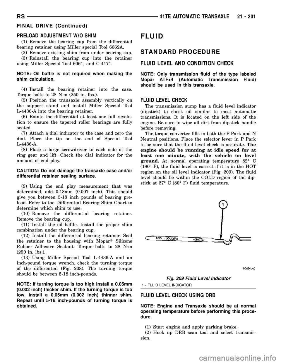
region on the oil level indicator (Fig. 209). The fluid
level should be within the COLD region of the dip-
stick at 27É C (80É F) fluid temperature.
FLUID LEVEL CHECK USING DRB
NOTE: Engine and Transaxle should be at normal
operating temperature before performing this proce-
dure.
(1) Start engine and apply parking brake.
(2) Hook up DRB scan tool and select transmis-
sion.
Fig. 209 Fluid Level Indicator
1 - FLUID LEVEL INDICATOR
RS41TE AUTOMATIC TRANSAXLE21 - 201
FINAL DRIVE (Continued)
Page 1823 of 2585
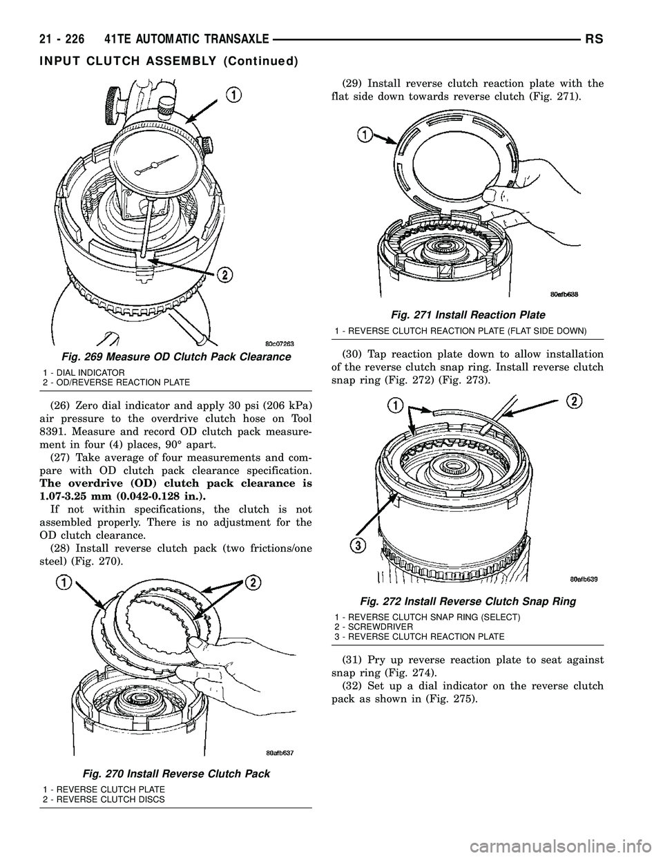
(26) Zero dial indicator and apply 30 psi (206 kPa)
air pressure to the overdrive clutch hose on Tool
8391. Measure and record OD clutch pack measure-
ment in four (4) places, 90É apart.
(27) Take average of four measurements and com-
pare with OD clutch pack clearance specification.
The overdrive (OD) clutch pack clearance is
1.07-3.25 mm (0.042-0.128 in.).
If not within specifications, the clutch is not
assembled properly. There is no adjustment for the
OD clutch clearance.
(28) Install reverse clutch pack (two frictions/one
steel) (Fig. 270).(29) Install reverse clutch reaction plate with the
flat side down towards reverse clutch (Fig. 271).
(30) Tap reaction plate down to allow installation
of the reverse clutch snap ring. Install reverse clutch
snap ring (Fig. 272) (Fig. 273).
(31) Pry up reverse reaction plate to seat against
snap ring (Fig. 274).
(32) Set up a dial indicator on the reverse clutch
pack as shown in (Fig. 275).
Fig. 269 Measure OD Clutch Pack Clearance
1 - DIAL INDICATOR
2 - OD/REVERSE REACTION PLATE
Fig. 270 Install Reverse Clutch Pack
1 - REVERSE CLUTCH PLATE
2 - REVERSE CLUTCH DISCS
Fig. 271 Install Reaction Plate
1 - REVERSE CLUTCH REACTION PLATE (FLAT SIDE DOWN)
Fig. 272 Install Reverse Clutch Snap Ring
1 - REVERSE CLUTCH SNAP RING (SELECT)
2 - SCREWDRIVER
3 - REVERSE CLUTCH REACTION PLATE
21 - 226 41TE AUTOMATIC TRANSAXLERS
INPUT CLUTCH ASSEMBLY (Continued)
Page 1961 of 2585
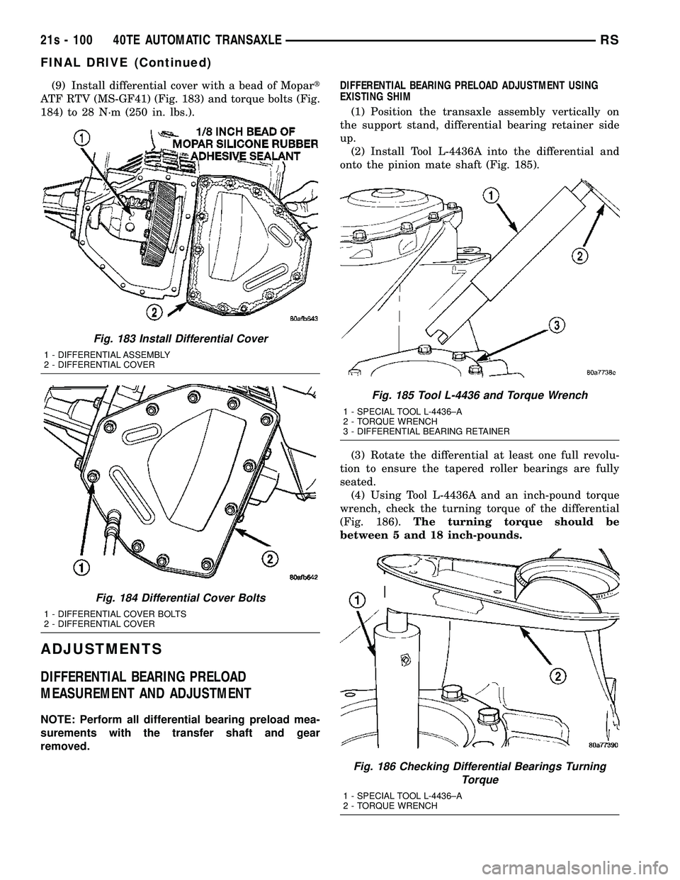
(9) Install differential cover with a bead of Mopart
ATF RTV (MS-GF41) (Fig. 183) and torque bolts (Fig.
184) to 28 N´m (250 in. lbs.).
ADJUSTMENTS
DIFFERENTIAL BEARING PRELOAD
MEASUREMENT AND ADJUSTMENT
NOTE: Perform all differential bearing preload mea-
surements with the transfer shaft and gear
removed. DIFFERENTIAL BEARING PRELOAD ADJUSTMENT USING
EXISTING SHIM
(1) Position the transaxle assembly vertically on
the support stand, differential bearing retainer side
up. (2) Install Tool L-4436A into the differential and
onto the pinion mate shaft (Fig. 185).
(3) Rotate the differential at least one full revolu-
tion to ensure the tapered roller bearings are fully
seated. (4) Using Tool L-4436A and an inch-pound torque
wrench, check the turning torque of the differential
(Fig. 186). The turning torque should be
between 5 and 18 inch-pounds.
Fig. 183 Install Differential Cover
1 - DIFFERENTIAL ASSEMBLY
2 - DIFFERENTIAL COVER
Fig. 184 Differential Cover Bolts
1 - DIFFERENTIAL COVER BOLTS
2 - DIFFERENTIAL COVER
Fig. 185 Tool L-4436 and Torque Wrench
1 - SPECIAL TOOL L-4436±A
2 - TORQUE WRENCH
3 - DIFFERENTIAL BEARING RETAINER
Fig. 186 Checking Differential Bearings Turning Torque
1 - SPECIAL TOOL L-4436±A
2 - TORQUE WRENCH
21s - 100 40TE AUTOMATIC TRANSAXLERS
FINAL DRIVE (Continued)
Page 1963 of 2585
PRELOAD ADJUSTMENT W/O SHIM(1) Remove the bearing cup from the differential
bearing retainer using Miller special Tool 6062A. (2) Remove existing shim from under bearing cup.
(3) Reinstall the bearing cup into the retainer
using Miller Special Tool 6061, and C-4171.
NOTE: Oil baffle is not required when making the
shim calculation.
(4) Install the bearing retainer into the case.
Torque bolts to 28 N ²m (250 in. lbs.).
(5) Position the transaxle assembly vertically on
the support stand and install Miller Special Tool
L-4436-A into the bearing retainer. (6) Rotate the differential at least one full revolu-
tion to ensure the tapered roller bearings are fully
seated. (7) Attach a dial indicator to the case and zero the
dial. Place the tip on the end of Special Tool
L-4436-A. (8) Place a large screwdriver to each side of the
ring gear and lift. Check the dial indicator for the
amount of end play.
CAUTION: Do not damage the transaxle case and/or
differential retainer sealing surface.
(9) Using the end play measurement that was
determined, add 0.18mm (0.007 inch). This should
give you between 5 and 18 inch pounds of bearing
preload. Refer to the Differential Bearing Shim Chart
to determine which shim to use. (10) Remove the differential bearing retainer.
Remove the bearing cup. (11) Install the oil baffle. Install the proper shim
combination under the bearing cup. (12) Install the differential bearing retainer. Seal
the retainer to the housing with Mopar tSilicone
Rubber Adhesive Sealant. Torque bolts to 28 N ²m
(250 in. lbs.). (13) Using Miller Special Tool L-4436-A and an
inch-pound torque wrench, check the turning torque
of the differential (Fig. 186). The turning torque
should be between 5-18 inch-pounds.
NOTE: If turning torque is too high install a 0.05mm
(0.002 inch) thicker shim. If the turning torque is too
low, install a 0.05mm (0.002 inch) thinner shim.
Repeat until 5-18 inch-pounds of turning torque is
obtained.FLUID
STANDARD PROCEDURE
FLUID LEVEL AND CONDITION CHECK
NOTE: Only transmission fluid of the type labeled
Mopar ATF+4 (Automatic Transmission Fluid)
should be used in this transaxle.
FLUID LEVEL CHECK
The transmission sump has a fluid level indicator
(dipstick) to check oil similar to most automatic
transmissions. It is located on the left side of the
engine. Be sure to wipe all dirt from dipstick handle
before removing. The torque converter fills in both the P Park and N
Neutral positions. Place the selector lever in P Park
to be sure that the fluid level check is accurate. The
engine should be running at idle speed for at
least one minute, with the vehicle on level
ground. At normal operating temperature 82É C
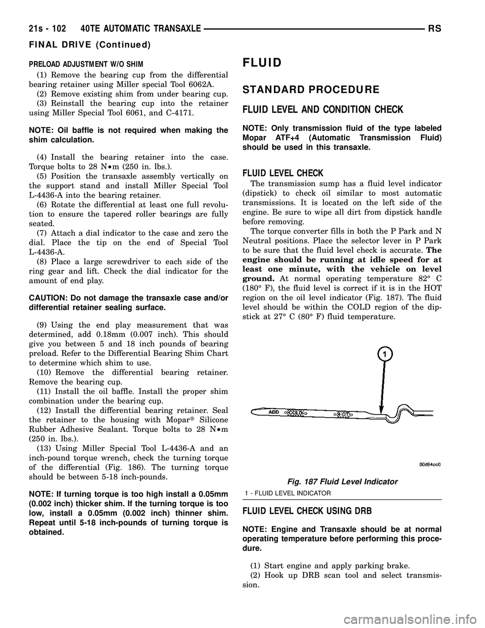
(180É F), the fluid level is correct if it is in the HOT
region on the oil level indicator (Fig. 187). The fluid
level should be within the COLD region of the dip-
stick at 27É C (80É F) fluid temperature.
FLUID LEVEL CHECK USING DRB
NOTE: Engine and Transaxle should be at normal
operating temperature before performing this proce-
dure.
(1) Start engine and apply parking brake.
(2) Hook up DRB scan tool and select transmis-
sion.
Fig. 187 Fluid Level Indicator
1 - FLUID LEVEL INDICATOR
21s - 102 40TE AUTOMATIC TRANSAXLERS
FINAL DRIVE (Continued)
Page 2197 of 2585
SEATS
TABLE OF CONTENTS
page page
CHILD SEAT MODULE, BENCH SEAT
REMOVAL.............................87
INSTALLATION
INSTALLATION.......................88
SYNCHRONIZING CABLE ADJUSTMENT . . . 88
QUAD CHILD SEAT
REMOVAL.............................89
INSTALLATION.........................89
HEADREST
REMOVAL.............................89
INSTALLATION.........................89
HEADREST SLEEVE
REMOVAL.............................90
INSTALLATION.........................90
RECLINER HANDLE
REMOVAL.............................90
INSTALLATION.........................90
ARMREST
REMOVAL.............................91
INSTALLATION.........................91
FRONT SEAT
REMOVAL.............................91
INSTALLATION.........................91
FRONT SEAT BACK
REMOVAL.............................92
INSTALLATION.........................92
FRONT SEATBACK ASSIST STRAP
REMOVAL.............................92
INSTALLATION.........................92
FRONT SEATBACK PANEL
REMOVAL.............................92
INSTALLATION.........................93
FRONT SEATBACK COVER
REMOVAL.............................93
INSTALLATION.........................93
FRONT/QUAD SEAT CUSHION
REMOVAL.............................93
INSTALLATION.........................93
FRONT SEAT CUSHION SIDE COVER
REMOVAL.............................94
INSTALLATION.........................94
FRONT SEAT RISER - MANUAL TRACK
REMOVAL.............................94
INSTALLATION.........................95
FRONT SEAT TRACK POWER ADJUSTER
REMOVAL.............................95
INSTALLATION.........................95
FRONT SEAT TRACK MANUAL ADJUSTER
REMOVAL.............................95INSTALLATION.........................95
FRONT SEAT TRACK - REAR COVER
REMOVAL.............................96
INSTALLATION.........................96
QUAD BUCKET SEAT SIDE SHIELD/
CUPHOLDER
REMOVAL.............................96
INSTALLATION.........................96
QUAD BUCKET SEAT SIDE SHIELD - NO
CUPHOLDER
REMOVAL.............................97
INSTALLATION.........................97
QUAD BUCKET SEAT RISER
REMOVAL.............................98
INSTALLATION.........................98
BUCKET SEAT BACK - QUAD BUCKET
REMOVAL.............................98
INSTALLATION.........................99
BENCH SEATBACK PANEL
REMOVAL.............................99
INSTALLATION.........................99
SEAT CUSHION COVER - QUAD BUCKET,
50/50 SPLIT, BENCH
REMOVAL............................100
INSTALLATION........................100
BENCH SEAT RISER - 50/50 SPLIT
REMOVAL............................100
INSTALLATION........................100
BENCH SEAT RISER - SECOND ROW
REMOVAL............................101
INSTALLATION........................101
BENCH SEAT RISER - THIRD ROW
REMOVAL............................101
INSTALLATION........................101
SEAT BACK HINGE COVERS - QUAD BUCKET,
50/50 SPLIT, BENCH
REMOVAL............................101
INSTALLATION........................101
BENCH SEAT BACK HINGE
REMOVAL............................102
INSTALLATION
INSTALLATION......................102
SYNCHRONIZING CABLE ADJUSTMENT . . 102
BENCH SEAT BACK
REMOVAL............................103
INSTALLATION........................103
BENCH SEAT BACK COVER
REMOVAL............................103
INSTALLATION........................103
23 - 86 SEATSRS
Page 2199 of 2585
INSTALLATION
INSTALLATION
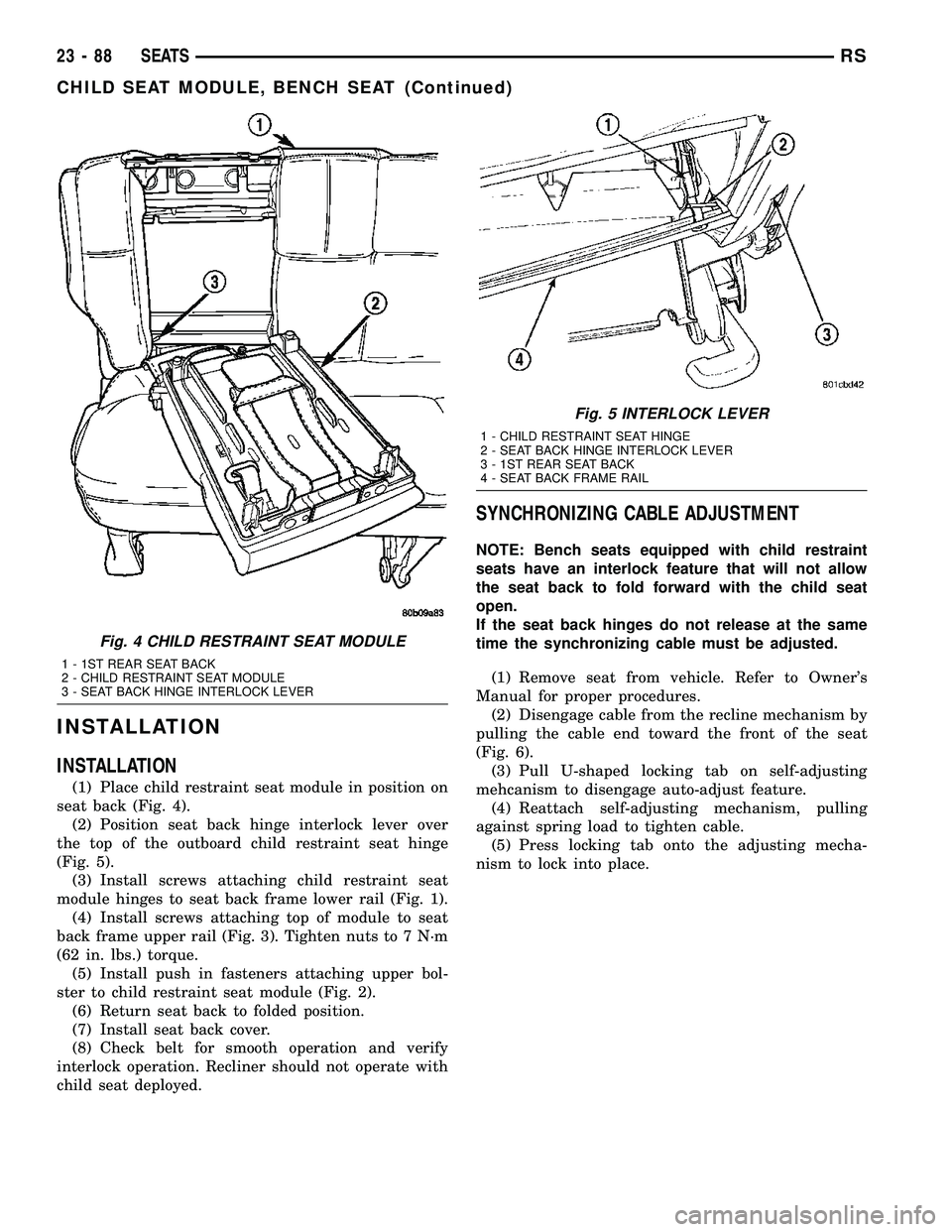
(1) Place child restraint seat module in position on
seat back (Fig. 4).
(2) Position seat back hinge interlock lever over
the top of the outboard child restraint seat hinge
(Fig. 5).
(3) Install screws attaching child restraint seat
module hinges to seat back frame lower rail (Fig. 1).
(4) Install screws attaching top of module to seat
back frame upper rail (Fig. 3). Tighten nuts to 7 N´m
(62 in. lbs.) torque.
(5) Install push in fasteners attaching upper bol-
ster to child restraint seat module (Fig. 2).
(6) Return seat back to folded position.
(7) Install seat back cover.
(8) Check belt for smooth operation and verify
interlock operation. Recliner should not operate with
child seat deployed.
SYNCHRONIZING CABLE ADJUSTMENT
NOTE: Bench seats equipped with child restraint
seats have an interlock feature that will not allow
the seat back to fold forward with the child seat
open.
If the seat back hinges do not release at the same
time the synchronizing cable must be adjusted.
(1) Remove seat from vehicle. Refer to Owner's
Manual for proper procedures.
(2) Disengage cable from the recline mechanism by
pulling the cable end toward the front of the seat
(Fig. 6).
(3) Pull U-shaped locking tab on self-adjusting
mehcanism to disengage auto-adjust feature.
(4) Reattach self-adjusting mechanism, pulling
against spring load to tighten cable.
(5) Press locking tab onto the adjusting mecha-
nism to lock into place.
Fig. 4 CHILD RESTRAINT SEAT MODULE
1 - 1ST REAR SEAT BACK
2 - CHILD RESTRAINT SEAT MODULE
3 - SEAT BACK HINGE INTERLOCK LEVER
Fig. 5 INTERLOCK LEVER
1 - CHILD RESTRAINT SEAT HINGE
2 - SEAT BACK HINGE INTERLOCK LEVER
3 - 1ST REAR SEAT BACK
4 - SEAT BACK FRAME RAIL
23 - 88 SEATSRS
CHILD SEAT MODULE, BENCH SEAT (Continued)
Page 2203 of 2585
FRONT SEAT BACK
REMOVAL
NOTE: On front seats equipped with side air bags,
the seatback is serviced as an assembly.
(1) Remove head rest sleeves. (Refer to 23 - BODY/
SEATS/HEADREST SLEEVE - REMOVAL)
(2) Remove the armrest. (Refer to 23 - BODY/
SEATS/ARMREST - REMOVAL)
(3) Remove the seatback recliner lever.
(4) Remove the lumbar adjustment lever.
(5) Remove both seat cushion side covers. (Refer to
23 - BODY/SEATS/FRONT SEAT CUSHION SIDE
COVER - REMOVAL)
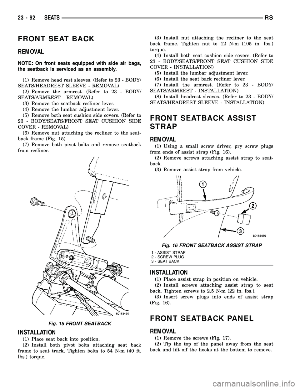
(6) Remove nut attaching the recliner to the seat-
back frame (Fig. 15).
(7) Remove both pivot bolts and remove seatback
from recliner.
INSTALLATION
(1) Place seat back into position.
(2) Install both pivot bolts attaching seat back
frame to seat track. Tighten bolts to 54 N´m (40 ft.
lbs.) torque.(3) Install nut attaching the recliner to the seat
back frame. Tighten nut to 12 N´m (105 in. lbs.)
torque.
(4) Install both seat cushion side covers. (Refer to
23 - BODY/SEATS/FRONT SEAT CUSHION SIDE
COVER - INSTALLATION)
(5) Install the lumbar adjustment lever.
(6) Install the seat back recliner lever.
(7) Install the armrest. (Refer to 23 - BODY/
SEATS/ARMREST - INSTALLATION)
(8) Install headrest sleeves. (Refer to 23 - BODY/
SEATS/HEADREST SLEEVE - INSTALLATION)
FRONT SEATBACK ASSIST
STRAP
REMOVAL
(1) Using a small screw driver, pry screw plugs
from ends of assist strap (Fig. 16).
(2) Remove screws attaching assist strap to seat-
back.
(3) Remove assist strap from vehicle.
INSTALLATION
(1) Place assist strap in position on vehicle.
(2) Install screws attaching assist strap to seat
back. Tighten screws to 2.5 N´m (22 in. lbs.).
(3) Insert screw plugs into ends of assist strap
(Fig. 16).
FRONT SEATBACK PANEL
REMOVAL
(1) Remove the screws (Fig. 17).
(2) Tip the top of the panel away from the seat
back and lift off the hooks at the bottom to remove.
Fig. 15 FRONT SEATBACK
Fig. 16 FRONT SEATBACK ASSIST STRAP
1 - ASSIST STRAP
2 - SCREW PLUG
3 - SEAT BACK
23 - 92 SEATSRS
Page 2213 of 2585
BENCH SEAT BACK HINGE
REMOVAL
NOTE: Bench seats equipped with child restraint
seats have an interlock feature that will not allow
the seat back to fold forward with the child seat
open.
(1) Remove the bench seat back upper and lower
hinge covers. (Refer to 23 - BODY/SEATS/SEAT
BACK HINGE COVERS - 50/50 SPLIT, BENCH -
REMOVAL)
(2) Remove the seat back. (Refer to 23 - BODY/
SEATS/BENCH SEAT BACK - REMOVAL)
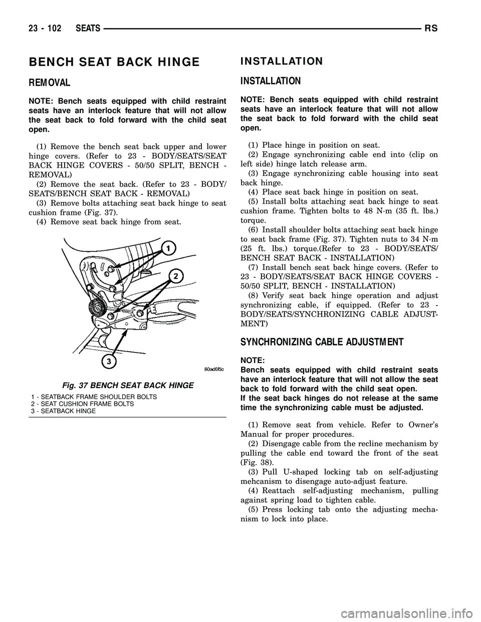
(3) Remove bolts attaching seat back hinge to seat
cushion frame (Fig. 37).
(4) Remove seat back hinge from seat.
INSTALLATION
INSTALLATION
NOTE: Bench seats equipped with child restraint
seats have an interlock feature that will not allow
the seat back to fold forward with the child seat
open.
(1) Place hinge in position on seat.
(2) Engage synchronizing cable end into (clip on
left side) hinge latch release arm.
(3) Engage synchronizing cable housing into seat
back hinge.
(4) Place seat back hinge in position on seat.
(5) Install bolts attaching seat back hinge to seat
cushion frame. Tighten bolts to 48 N´m (35 ft. lbs.)
torque.
(6) Install shoulder bolts attaching seat back hinge
to seat back frame (Fig. 37). Tighten nuts to 34 N´m
(25 ft. lbs.) torque.(Refer to 23 - BODY/SEATS/
BENCH SEAT BACK - INSTALLATION)
(7) Install bench seat back hinge covers. (Refer to
23 - BODY/SEATS/SEAT BACK HINGE COVERS -
50/50 SPLIT, BENCH - INSTALLATION)
(8) Verify seat back hinge operation and adjust
synchronizing cable, if equipped. (Refer to 23 -
BODY/SEATS/SYNCHRONIZING CABLE ADJUST-
MENT)
SYNCHRONIZING CABLE ADJUSTMENT
NOTE:
Bench seats equipped with child restraint seats
have an interlock feature that will not allow the seat
back to fold forward with the child seat open.
If the seat back hinges do not release at the same
time the synchronizing cable must be adjusted.
(1) Remove seat from vehicle. Refer to Owner's
Manual for proper procedures.
(2) Disengage cable from the recline mechanism by
pulling the cable end toward the front of the seat
(Fig. 38).
(3) Pull U-shaped locking tab on self-adjusting
mehcanism to disengage auto-adjust feature.
(4) Reattach self-adjusting mechanism, pulling
against spring load to tighten cable.
(5) Press locking tab onto the adjusting mecha-
nism to lock into place.
Fig. 37 BENCH SEAT BACK HINGE
1 - SEATBACK FRAME SHOULDER BOLTS
2 - SEAT CUSHION FRAME BOLTS
3 - SEATBACK HINGE
23 - 102 SEATSRS