2004 DODGE TOWN AND COUNTRY steering
[x] Cancel search: steeringPage 1567 of 2585
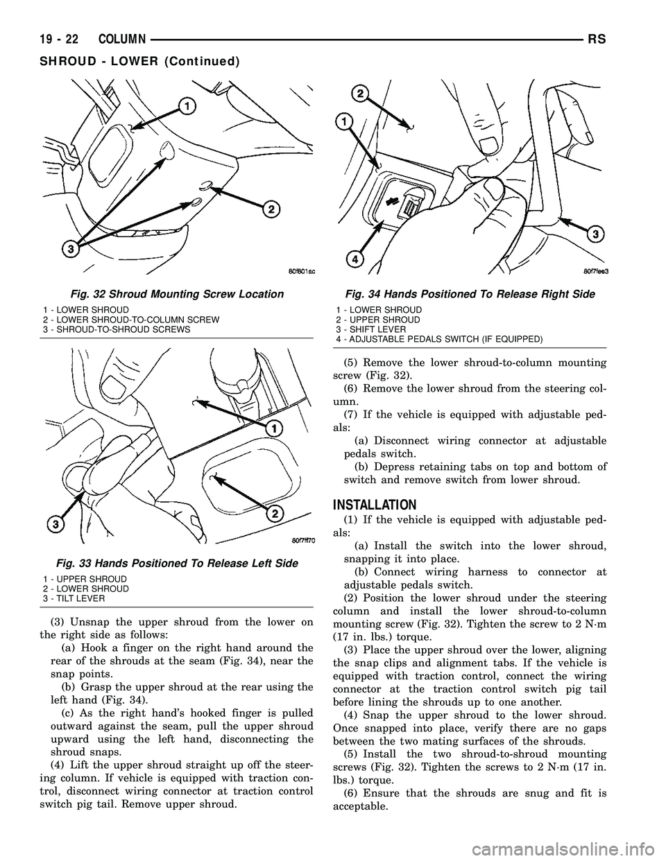
(3) Unsnap the upper shroud from the lower on
the right side as follows:
(a) Hook a finger on the right hand around the
rear of the shrouds at the seam (Fig. 34), near the
snap points.
(b) Grasp the upper shroud at the rear using the
left hand (Fig. 34).
(c) As the right hand's hooked finger is pulled
outward against the seam, pull the upper shroud
upward using the left hand, disconnecting the
shroud snaps.
(4) Lift the upper shroud straight up off the steer-
ing column. If vehicle is equipped with traction con-
trol, disconnect wiring connector at traction control
switch pig tail. Remove upper shroud.(5) Remove the lower shroud-to-column mounting
screw (Fig. 32).
(6) Remove the lower shroud from the steering col-
umn.
(7) If the vehicle is equipped with adjustable ped-
als:
(a) Disconnect wiring connector at adjustable
pedals switch.
(b) Depress retaining tabs on top and bottom of
switch and remove switch from lower shroud.
INSTALLATION
(1) If the vehicle is equipped with adjustable ped-
als:
(a) Install the switch into the lower shroud,
snapping it into place.
(b) Connect wiring harness to connector at
adjustable pedals switch.
(2) Position the lower shroud under the steering
column and install the lower shroud-to-column
mounting screw (Fig. 32). Tighten the screw to 2 N´m
(17 in. lbs.) torque.
(3) Place the upper shroud over the lower, aligning
the snap clips and alignment tabs. If the vehicle is
equipped with traction control, connect the wiring
connector at the traction control switch pig tail
before lining the shrouds up to one another.
(4) Snap the upper shroud to the lower shroud.
Once snapped into place, verify there are no gaps
between the two mating surfaces of the shrouds.
(5) Install the two shroud-to-shroud mounting
screws (Fig. 32). Tighten the screws to 2 N´m (17 in.
lbs.) torque.
(6) Ensure that the shrouds are snug and fit is
acceptable.
Fig. 32 Shroud Mounting Screw Location
1 - LOWER SHROUD
2 - LOWER SHROUD-TO-COLUMN SCREW
3 - SHROUD-TO-SHROUD SCREWS
Fig. 33 Hands Positioned To Release Left Side
1 - UPPER SHROUD
2 - LOWER SHROUD
3 - TILT LEVER
Fig. 34 Hands Positioned To Release Right Side
1 - LOWER SHROUD
2 - UPPER SHROUD
3 - SHIFT LEVER
4 - ADJUSTABLE PEDALS SWITCH (IF EQUIPPED)
19 - 22 COLUMNRS
SHROUD - LOWER (Continued)
Page 1568 of 2585
SHROUD - UPPER
REMOVAL
(1) Remove the two shroud-to-shroud mounting
screws from the lower shroud (Fig. 32).
(2) Unsnap the upper shroud from the lower on
the left side as follows:
(a) Hook a finger on the left hand around the
rear of the shrouds at the seam (Fig. 33), near the
snap points.
(b) Grasp the upper shroud at the rear using the
right hand (Fig. 33).
(c) As the left hand's hooked finger is pulled out-
ward against the seam, pull the upper shroud
upward using the right hand, disconnecting the
shroud snaps.
(3) Unsnap the upper shroud from the lower on
the right side as follows:
(a) Hook a finger on the right hand around the
rear of the shrouds at the seam (Fig. 34), near the
snap points.
(b) Grasp the upper shroud at the rear using the
left hand (Fig. 34).
(c) As the right hand's hooked finger is pulled
outward against the seam, pull the upper shroud
upward using the left hand, disconnecting the
shroud snaps.
(4) Lift the upper shroud straight up off the steer-
ing column. If vehicle is equipped with traction con-
trol, disconnect wiring connector at traction control
switch pig tail. If vehicle is equipped with power fold-
away mirrors (Export), disconnect wiring connector
at mirror switch pig tail. Remove upper shroud.
(5) If vehicle is equipped with traction control,
remove traction control switch from shroud.
(6) If vehicle is equipped with power foldaway mir-
rors (Export), remove power fold-away switch from
upper shroud.
INSTALLATION
(1) If the vehicle is equipped with power foldaway
mirrors (Export), install the power fold-away switch
in the upper shroud.
(2) If vehicle is equipped with traction control,
install the traction control switch in the upper
shroud.
(3) Place the upper shroud over the lower shroud,
aligning the snap clips and alignment tabs. If the
vehicle is equipped with traction control, connect the
wiring connector at the traction control switch pig
tail before lining the shrouds up to one another.
(4) Snap the upper shroud to the lower shroud.
Once snapped into place, verify there are no gaps
between the two mating surfaces of the shrouds.(5) Install the two shroud-to-shroud mounting
screws (Fig. 32). Tighten the screws to 2 N´m (17 in.
lbs.) torque.
(6) Ensure that the shrouds are snug and fit is
acceptable.
STEERING WHEEL
REMOVAL
NOTE: Before proceeding, (Refer to 19 - STEERING/
COLUMN - WARNING)(Refer to 8 - ELECTRICAL/RE-
STRAINTS - WARNING).
(1) Adjust the steering wheel so that the tires are
in thestraight-aheadposition.
(2) Disconnect and isolate the battery negative
cable.
(3) Remove the two bolts from the rear of the
steering wheel attaching the driver airbag. Lift the
airbag from the steering wheel.
(4) Disconnect airbag squib wiring connectors from
the airbag and the horn/speed control switch pigtail
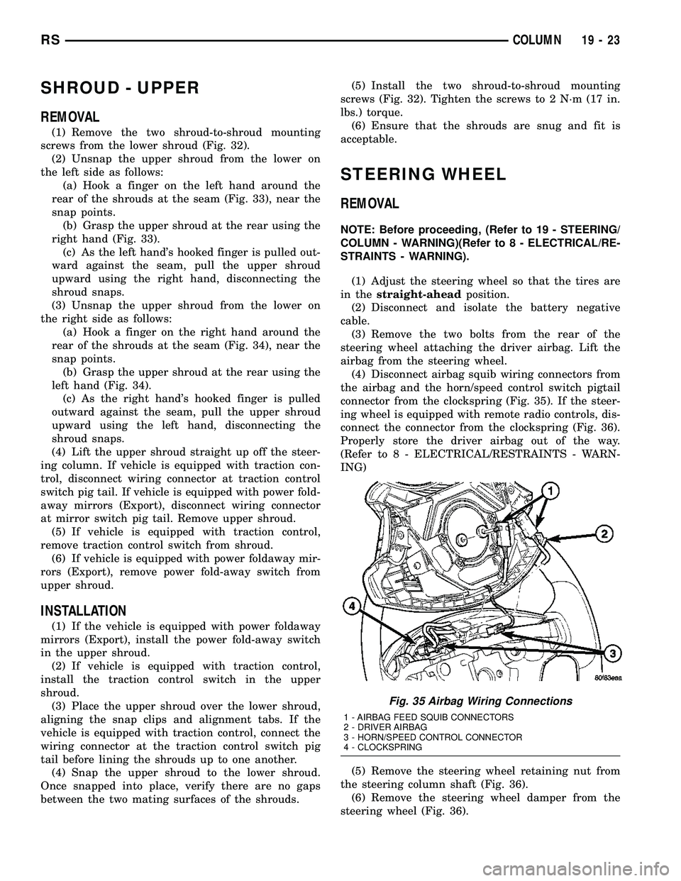
connector from the clockspring (Fig. 35). If the steer-
ing wheel is equipped with remote radio controls, dis-
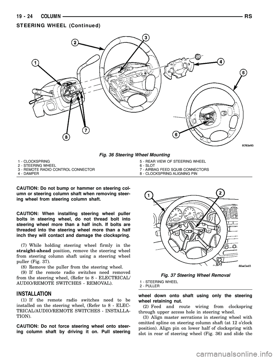
connect the connector from the clockspring (Fig. 36).
Properly store the driver airbag out of the way.
(Refer to 8 - ELECTRICAL/RESTRAINTS - WARN-
ING)
(5) Remove the steering wheel retaining nut from
the steering column shaft (Fig. 36).
(6) Remove the steering wheel damper from the
steering wheel (Fig. 36).
Fig. 35 Airbag Wiring Connections
1 - AIRBAG FEED SQUIB CONNECTORS
2 - DRIVER AIRBAG
3 - HORN/SPEED CONTROL CONNECTOR
4 - CLOCKSPRING
RSCOLUMN19-23
Page 1569 of 2585
CAUTION: Do not bump or hammer on steering col-
umn or steering column shaft when removing steer-
ing wheel from steering column shaft.
CAUTION: When installing steering wheel puller
bolts in steering wheel, do not thread bolt into
steering wheel more than a half inch. If bolts are
threaded into the steering wheel more than a half
inch they will contact and damage the clockspring.
(7) While holding steering wheel firmly in the
straight-aheadposition, remove the steering wheel
from steering column shaft using a steering wheel
puller (Fig. 37).
(8) Remove the puller from the steering wheel.
(9) If the remote radio switches need removed
from the steering wheel, (Refer to 8 - ELECTRICAL/
AUDIO/REMOTE SWITCHES - REMOVAL).
INSTALLATION
(1) If the remote radio switches need to be
installed on the steering wheel, (Refer to 8 - ELEC-
TRICAL/AUDIO/REMOTE SWITCHES - INSTALLA-
TION).
CAUTION: Do not force steering wheel onto steer-
ing column shaft by driving it on. Pull steeringwheel down onto shaft using only the steering
wheel retaining nut.
(2) Feed and route wiring from clockspring
through upper access hole in steering wheel.
(3) Align master serrations in steering wheel with
omitted spline on steering column shaft (at 12 o'clock
position). Align pin on lower half of clockspring with
slot in rear of steering wheel (Fig. 36) and slide the
Fig. 36 Steering Wheel Mounting
1 - CLOCKSPRING
2 - STEERING WHEEL
3 - REMOTE RADIO CONTROL CONNECTOR
4 - DAMPER5 - REAR VIEW OF STEERING WHEEL
6 - SLOT
7 - AIRBAG FEED SQUIB CONNECTORS
8 - CLOCKSPRING ALIGNING PIN
Fig. 37 Steering Wheel Removal
1 - STEERING WHEEL
2 - PULLER
19 - 24 COLUMNRS
STEERING WHEEL (Continued)
Page 1570 of 2585
steering wheel onto the steering column shaft by
hand. Use care not to pinch any wiring.
NOTE: Before installing the damper on the steering
wheel, inspect the damper to ensure the rubber iso-
lator on the damper is not deteriorated or damaged.
If the damper is installed with a damaged isolator, a
buzz, squeak or rattle condition may develop.
(4) Install the steering wheel damper on the steer-
ing wheel (Fig. 36).
(5) Install the steering wheel retaining nut.
Tighten the steering wheel retaining nut to 61 N´m
(45 ft. lbs.) torque.(6) If the steering wheel is equipped with remote
radio controls, connect the wiring connector to the
clockspring (Fig. 36).
(7) Connect the airbag squib wiring connectors to
the airbag and the horn/speed control switch pigtail
connector to the clockspring (Fig. 35).
(8) Install the driver airbag in the steering wheel.
Install and tighten the airbag attaching bolts to 10
N´m (90 in. lbs.) torque.
(9) To properly connect the battery and test the
airbag system, (Refer to 8 - ELECTRICAL/RE-
STRAINTS - DIAGNOSIS AND TESTING).
RSCOLUMN19-25
STEERING WHEEL (Continued)
Page 1571 of 2585
GEAR
TABLE OF CONTENTS
page page
GEAR
DESCRIPTION.........................26
OPERATION...........................27
WARNING
WARNINGS AND CAUTIONS.............27
REMOVAL
REMOVAL - LHD GEAR.................27
REMOVAL - RHD GEAR................31INSTALLATION
INSTALLATION - LHD GEAR.............32
INSTALLATION - RHD GEAR.............33
SPECIAL TOOLS
POWER STEERING GEAR..............34
OUTER TIE ROD
REMOVAL.............................34
INSTALLATION.........................34
GEAR
DESCRIPTION
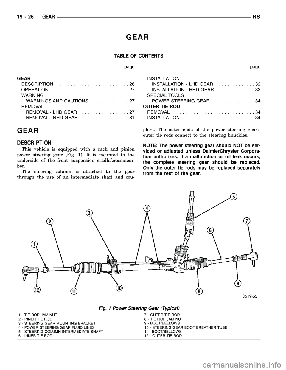
This vehicle is equipped with a rack and pinion
power steering gear (Fig. 1). It is mounted to the
underside of the front suspension cradle/crossmem-
ber.
The steering column is attached to the gear
through the use of an intermediate shaft and cou-plers. The outer ends of the power steering gear's
outer tie rods connect to the steering knuckles.
NOTE: The power steering gear should NOT be ser-
viced or adjusted unless DaimlerChrysler Corpora-
tion authorizes. If a malfunction or oil leak occurs,
the complete steering gear should be replaced.
Only the outer tie rods may be replaced separately
from the rest of the gear.
Fig. 1 Power Steering Gear (Typical)
1 - TIE ROD JAM NUT
2 - INNER TIE ROD
3 - STEERING GEAR MOUNTING BRACKET
4 - POWER STEERING GEAR FLUID LINES
5 - STEERING COLUMN INTERMEDIATE SHAFT
6 - INNER TIE ROD7 - OUTER TIE ROD
8 - TIE ROD JAM NUT
9 - BOOT/BELLOWS
10 - STEERING GEAR BOOT BREATHER TUBE
11 - BOOT/BELLOWS
12 - OUTER TIE ROD
19 - 26 GEARRS
Page 1572 of 2585
OPERATION
Turning of the steering wheel is converted into lin-
ear (side-to-side) travel through the meshing of the
helical pinion teeth with the rack teeth in the steer-
ing gear. This travel pushes and pulls the tie rods to
change the direction of the vehicle's front wheels.
Power assist steering provided by the power steer-
ing pump is controlled by an open center, rotary type
control valve which directs oil from the pump to
either side of the integral rack piston upon demand.
Road feel is controlled by the diameter of a torsion
bar which initially steers the vehicle. As required
steering effort increases, as in a turn, the torsion bar
twists, causing relative rotary motion between the
rotary valve body and the valve spool. This move-
ment directs oil behind the integral rack piston
which, in turn, builds hydraulic pressure and assists
in the turning effort.
Manual steering control of the vehicle can be main-
tained if power steering assist is lost. However,
under this condition, steering effort is significantly
increased.
WARNING
WARNINGS AND CAUTIONS
WARNING: POWER STEERING FLUID, ENGINE
PARTS AND EXHAUST SYSTEM MAY BE
EXTREMELY HOT IF ENGINE HAS BEEN RUNNING.
DO NOT START ENGINE WITH ANY LOOSE OR DIS-
CONNECTED HOSES. DO NOT ALLOW HOSES TO
TOUCH HOT EXHAUST MANIFOLD OR CATALYST.
WARNING: FLUID LEVEL SHOULD BE CHECKED
WITH THE ENGINE OFF TO PREVENT PERSONAL
INJURY FROM MOVING PARTS.
CAUTION: When the system is open, cap all open
ends of the hoses, power steering pump fittings or
power steering gear ports to prevent entry of for-
eign material into the components.
REMOVAL
REMOVAL - LHD GEAR
(1) Remove cap from power steering fluid reser-
voir.
(2) Using a siphon pump, remove as much fluid as
possible from the power steering fluid reservoir.Use
care not to damage the filter mesh below the
fluid surface.
CAUTION: Locking the steering column in the
straight-ahead position will prevent the clockspring
from being accidentally over-extended when the
steering column is disconnected from the interme-
diate steering coupler.
(3) Position the steering wheel in the STRAIGHT-
AHEAD position. Lock the steering wheel in place
using a steering wheel holding tool.
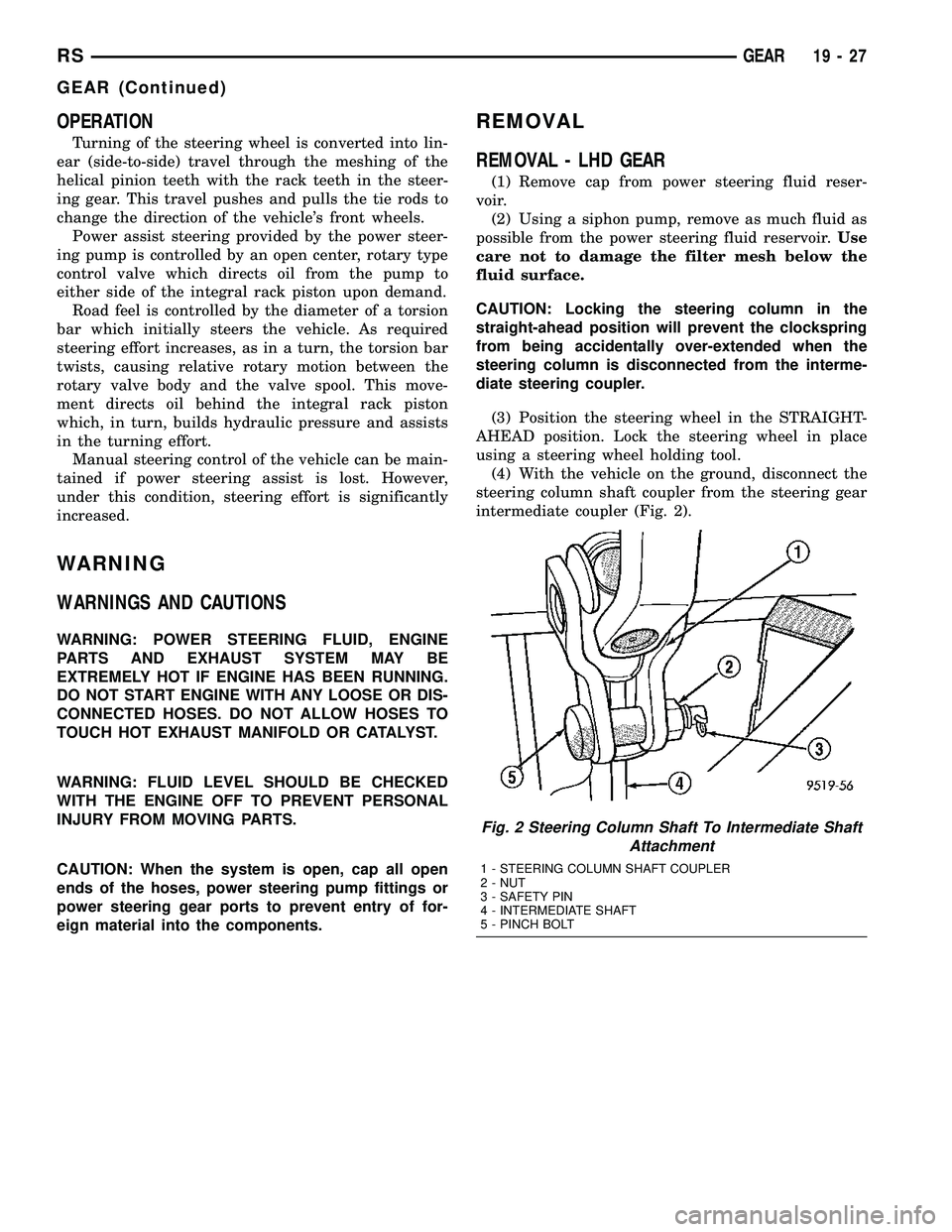
(4) With the vehicle on the ground, disconnect the
steering column shaft coupler from the steering gear
intermediate coupler (Fig. 2).
Fig. 2 Steering Column Shaft To Intermediate Shaft
Attachment
1 - STEERING COLUMN SHAFT COUPLER
2 - NUT
3 - SAFETY PIN
4 - INTERMEDIATE SHAFT
5 - PINCH BOLT
RSGEAR19-27
GEAR (Continued)
Page 1573 of 2585
(5) Raise vehicle. (Refer to LUBRICATION &
MAINTENANCE/HOISTING - STANDARD PROCE-
DURE)
(6) Remove front wheel and tire assemblies.
(7) Remove front emissions vapor canister. (Refer
to 25 - EMISSIONS CONTROL/EVAPORATIVE
EMISSIONS/VAPOR CANISTER - REMOVAL)
(8) Remove a single hose at power steering cooler
and allow fluid to drain.
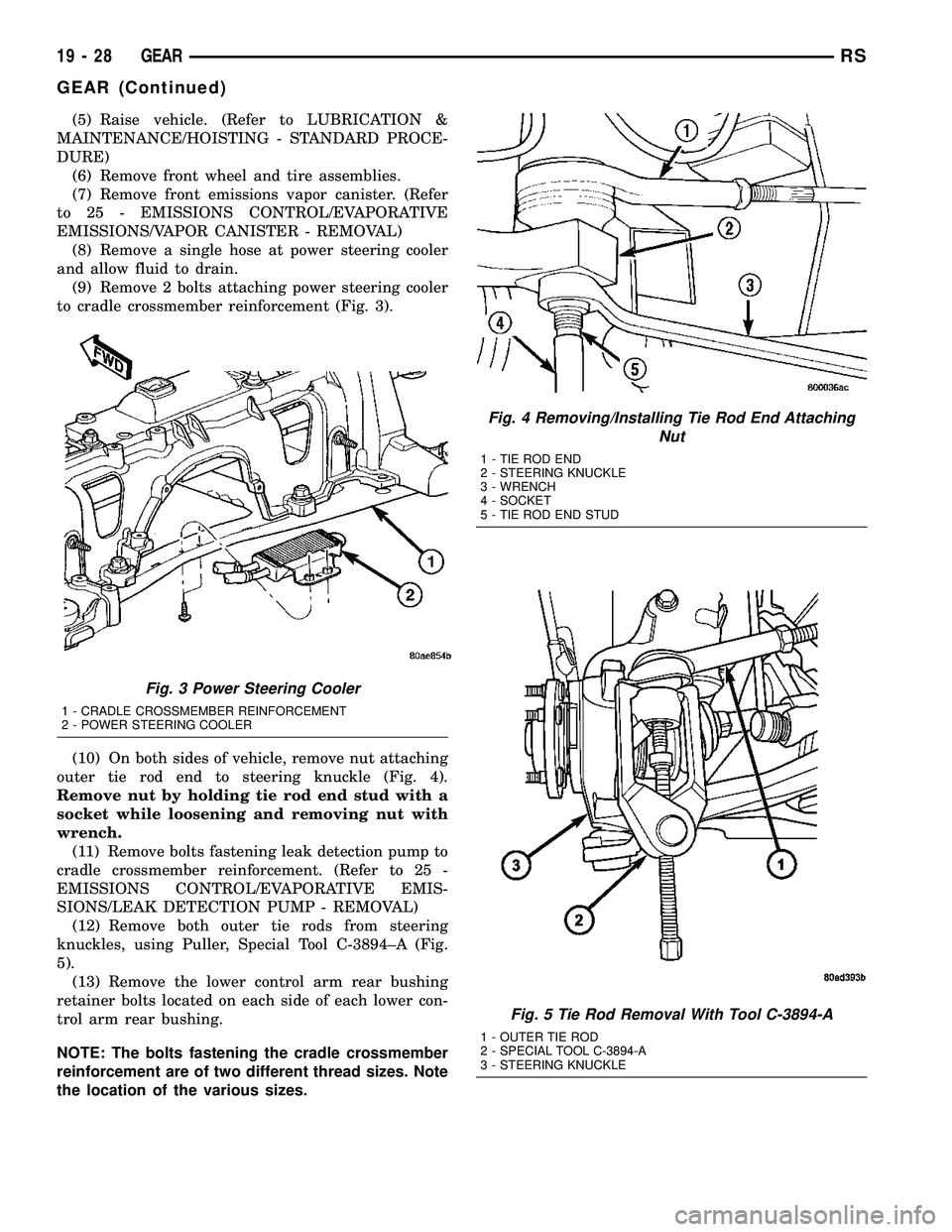
(9) Remove 2 bolts attaching power steering cooler
to cradle crossmember reinforcement (Fig. 3).
(10) On both sides of vehicle, remove nut attaching
outer tie rod end to steering knuckle (Fig. 4).
Remove nut by holding tie rod end stud with a
socket while loosening and removing nut with
wrench.
(11) Remove bolts fastening leak detection pump to
cradle crossmember reinforcement. (Refer to 25 -
EMISSIONS CONTROL/EVAPORATIVE EMIS-
SIONS/LEAK DETECTION PUMP - REMOVAL)
(12) Remove both outer tie rods from steering
knuckles, using Puller, Special Tool C-3894±A (Fig.
5).
(13) Remove the lower control arm rear bushing
retainer bolts located on each side of each lower con-
trol arm rear bushing.
NOTE: The bolts fastening the cradle crossmember
reinforcement are of two different thread sizes. Note
the location of the various sizes.
Fig. 3 Power Steering Cooler
1 - CRADLE CROSSMEMBER REINFORCEMENT
2 - POWER STEERING COOLER
Fig. 4 Removing/Installing Tie Rod End Attaching
Nut
1 - TIE ROD END
2 - STEERING KNUCKLE
3 - WRENCH
4 - SOCKET
5 - TIE ROD END STUD
Fig. 5 Tie Rod Removal With Tool C-3894-A
1 - OUTER TIE ROD
2 - SPECIAL TOOL C-3894-A
3 - STEERING KNUCKLE
19 - 28 GEARRS
GEAR (Continued)
Page 1574 of 2585
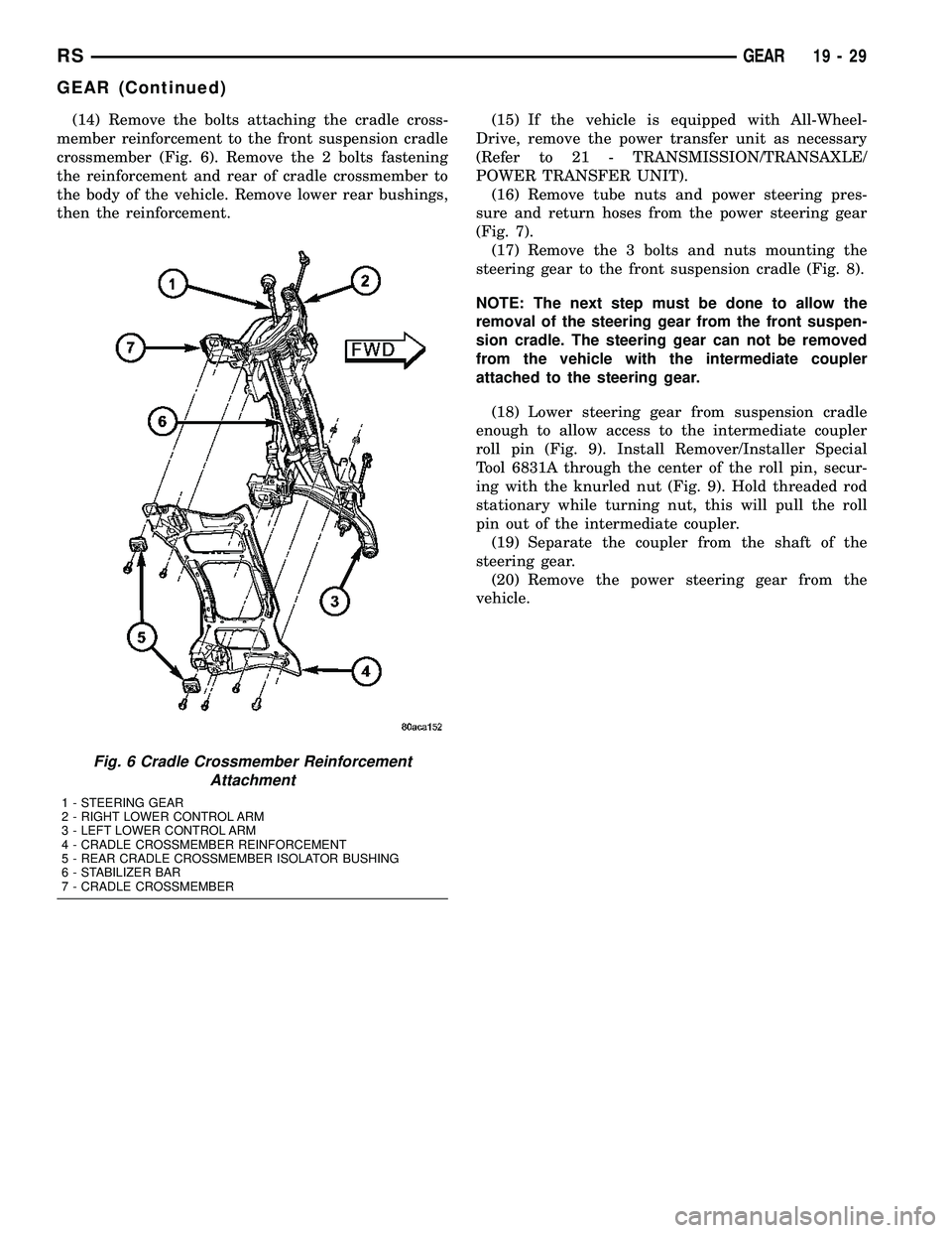
(14) Remove the bolts attaching the cradle cross-
member reinforcement to the front suspension cradle
crossmember (Fig. 6). Remove the 2 bolts fastening
the reinforcement and rear of cradle crossmember to
the body of the vehicle. Remove lower rear bushings,
then the reinforcement.(15) If the vehicle is equipped with All-Wheel-
Drive, remove the power transfer unit as necessary
(Refer to 21 - TRANSMISSION/TRANSAXLE/
POWER TRANSFER UNIT).
(16) Remove tube nuts and power steering pres-
sure and return hoses from the power steering gear
(Fig. 7).
(17) Remove the 3 bolts and nuts mounting the
steering gear to the front suspension cradle (Fig. 8).
NOTE: The next step must be done to allow the
removal of the steering gear from the front suspen-
sion cradle. The steering gear can not be removed
from the vehicle with the intermediate coupler
attached to the steering gear.
(18) Lower steering gear from suspension cradle
enough to allow access to the intermediate coupler
roll pin (Fig. 9). Install Remover/Installer Special
Tool 6831A through the center of the roll pin, secur-
ing with the knurled nut (Fig. 9). Hold threaded rod
stationary while turning nut, this will pull the roll
pin out of the intermediate coupler.
(19) Separate the coupler from the shaft of the
steering gear.
(20) Remove the power steering gear from the
vehicle.
Fig. 6 Cradle Crossmember Reinforcement
Attachment
1 - STEERING GEAR
2 - RIGHT LOWER CONTROL ARM
3 - LEFT LOWER CONTROL ARM
4 - CRADLE CROSSMEMBER REINFORCEMENT
5 - REAR CRADLE CROSSMEMBER ISOLATOR BUSHING
6 - STABILIZER BAR
7 - CRADLE CROSSMEMBER
RSGEAR19-29
GEAR (Continued)