Page 66 of 273
Speed Sensitive Intermittent Wiper System
Use the intermittent wiper when weather conditions
make a single wiping cycle, with a variable pause be-
tween cycles, desirable. Turn the lever to the delay
position, then select the delay interval. The delay can be
regulated from a maximum of approximately 18 seconds
between cycles, to a cycle every 1/2 second.
NOTE:The wiper delay times depend on vehicle speed.
If the vehicle is moving less than 16 km/h (10 mph),
delay times will be doubled.
TILT STEERING COLUMN
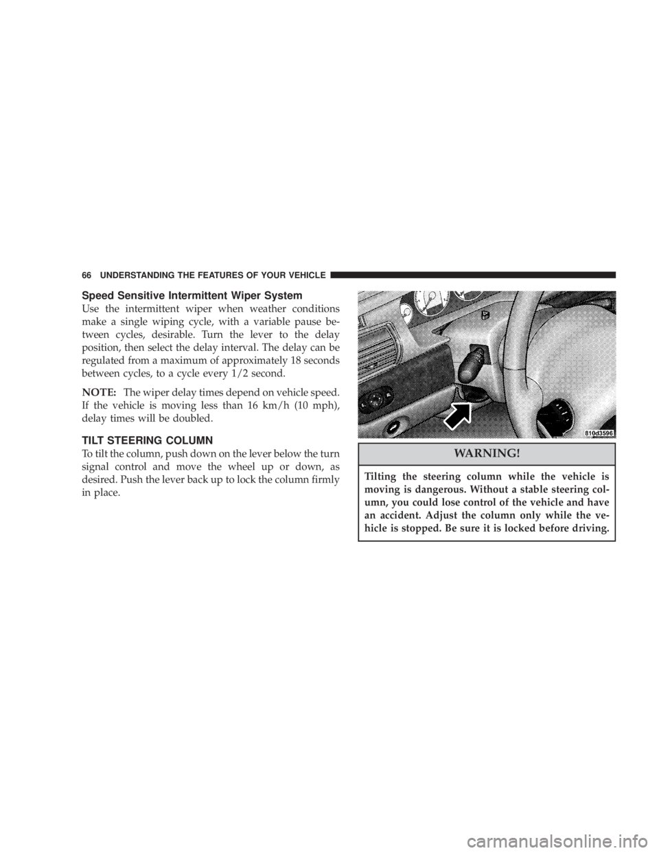
To tilt the column, push down on the lever below the turn
signal control and move the wheel up or down, as
desired. Push the lever back up to lock the column firmly
in place.WARNING!
Tilting the steering column while the vehicle is
moving is dangerous. Without a stable steering col-
umn, you could lose control of the vehicle and have
an accident. Adjust the column only while the ve-
hicle is stopped. Be sure it is locked before driving.
66 UNDERSTANDING THE FEATURES OF YOUR VEHICLE
Page 67 of 273
TRACTION CONTROLÐ IF EQUIPPED
To turn the Traction Control System Off, press
the switch located on the top of the steering
column, to the right of the hazard switch, until
the Traction Control indicator in the instrument
cluster lights up.
To turn the Traction Control System On, press the switch
until the Traction Control indicator in the instrument
cluster turns off.
NOTE:The Traction Control System is enabled each
time the ignition switch is turned On. This will occur
even if you used the switch to turn the system off before
powering down or turning the ignition to Lock.
ELECTRONIC SPEED CONTROLÐ IF EQUIPPED
When engaged, this device will control the throttle op-
eration to maintain a constant vehicle speed between 30
mph (48 km/h) and 85 mph (137 km/h). The controls are
on the steering wheel.
UNDERSTANDING THE FEATURES OF YOUR VEHICLE 67
3
Page 86 of 273
5. Tachometer
The red area of the scale shows the maximum permissible
engine revolutions-per-minute (rpm x 1000) for each gear
range. Before reaching the red area (over 6,500 rpm), ease
up on the accelerator to prevent engine over speed.
6. Turn Signal Indicators
The arrows will flash in unison with the exterior turn
signal, when using the turn signal lever.
7. High Beam Indicator
This light shows that the headlights are on high
beam. Pull the turn signal lever toward the
steering wheel to switch the headlights from high or
low beam.
8. Speedometer
Shows the vehicle speed in miles-per-hour and
kilometers-per-hour.
9. Charging System Light
This light shows the status of the electrical
charging system. The light should come on
briefly when the ignition is first turned on and remain
on briefly as a bulb check. If the light stays on orcomes on while driving, turn off some of the vehicle's
electrical devices, such as the Fog Lights or Rear
Defroster. If the Charging System Light remains on, it
means that the vehicle is experiencing a problem with
the charging system. Obtain SERVICE IMMEDI-
ATELY. See your local authorized dealer.
10. Malfunction Indicator Light
This light is part of an onboard diagnostic
system called OBD that monitors engine and
automatic transmission control systems. The
light will illuminate as long as the key is in the ON
position, prior to engine start up. Approximately 15
seconds later the MIL may blink for 10 seconds then
resume to full illumination. (See ªEMISSIONS IN-
SPECTION AND MAINTENANCE PROGRAMSº in
the ªMAINTAINING YOUR VEHICLEº section of
your Owner Manual for more details). If the bulb does
not come on when turning the key from OFF to ON,
have the condition checked promptly.
Certain conditions such as a loose or missing gas cap or
poor fuel quality may illuminate the light after engine
start. The vehicle should be serviced if the light stays on
86 UNDERSTANDING YOUR INSTRUMENT PANEL
Page 117 of 273
REMOTE SOUND SYSTEM CONTROLS Ð IF
EQUIPPED
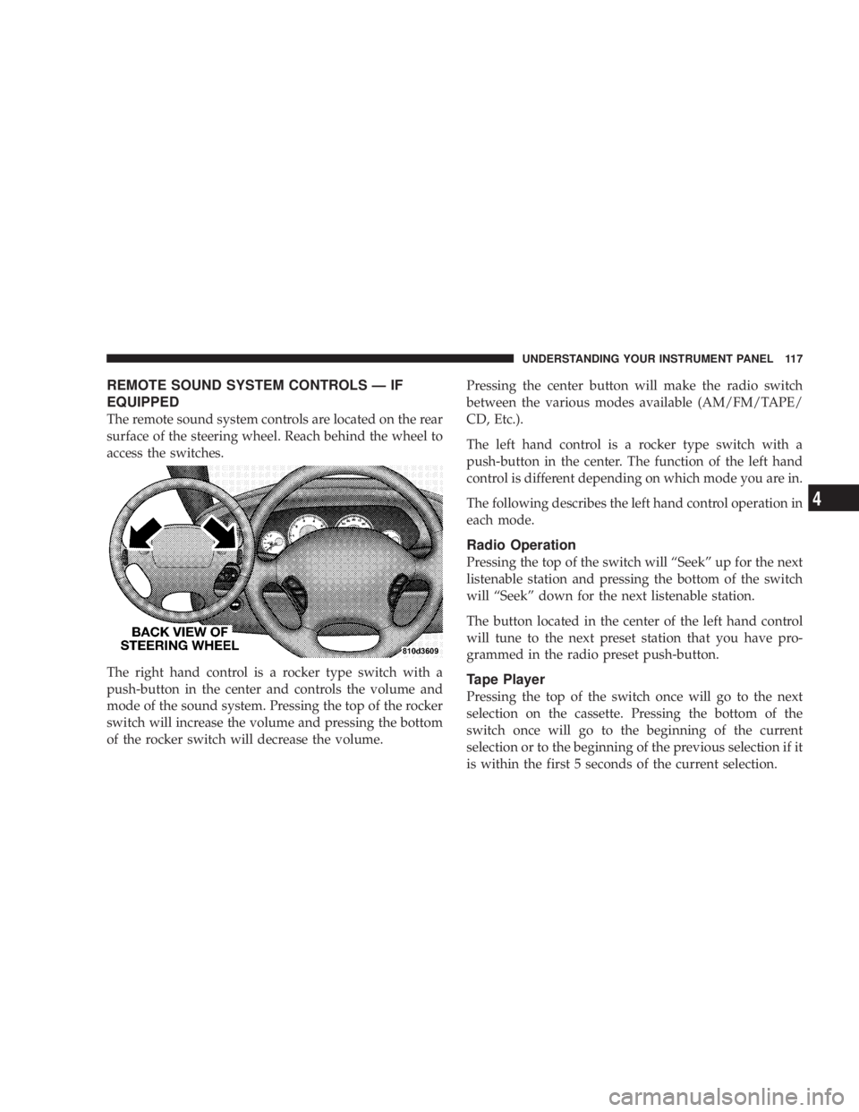
The remote sound system controls are located on the rear
surface of the steering wheel. Reach behind the wheel to
access the switches.
The right hand control is a rocker type switch with a
push-button in the center and controls the volume and
mode of the sound system. Pressing the top of the rocker
switch will increase the volume and pressing the bottom
of the rocker switch will decrease the volume.Pressing the center button will make the radio switch
between the various modes available (AM/FM/TAPE/
CD, Etc.).
The left hand control is a rocker type switch with a
push-button in the center. The function of the left hand
control is different depending on which mode you are in.
The following describes the left hand control operation in
each mode.
Radio Operation
Pressing the top of the switch will ªSeekº up for the next
listenable station and pressing the bottom of the switch
will ªSeekº down for the next listenable station.
The button located in the center of the left hand control
will tune to the next preset station that you have pro-
grammed in the radio preset push-button.
Tape Player
Pressing the top of the switch once will go to the next
selection on the cassette. Pressing the bottom of the
switch once will go to the beginning of the current
selection or to the beginning of the previous selection if it
is within the first 5 seconds of the current selection.
UNDERSTANDING YOUR INSTRUMENT PANEL 117
4
Page 128 of 273
NAnti-Lock Brake System (ABS) Ð If
Equipped...........................141
mPower Steering........................142
mTraction Control Ð If Equipped...........142
mTire Safety Information..................143
NTire Markings........................143
NTire Identification Number (TIN)..........146
NTire Loading And Tire Pressure...........147
mTiresÐGeneral Information...............150
NTire Pressure.........................150
NTire Inflation Pressures.................151
NRadial-Ply Tires......................153
NCompact Spare Tire Ð If Equipped.........153
NTire Spinning........................154
NTread Wear Indicators..................155
NReplacement Tires.....................155NAlignment And Balance.................156
mTire Chains...........................157
mSnow Tires...........................157
mTire Rotation Recommendations...........157
mAutoStick Ð If Equipped................158
NAutoStick Operation...................158
NAutoStick General Information............159
mFuel Requirements.....................160
NReformulated Gasoline.................160
NGasoline/Oxygenate Blends..............160
NMMT In Gasoline.....................161
NSulfur In Gasoline.....................161
NMaterials Added To Fuel................162
mAdding Fuel..........................162
NFuel Filler Cap (Gas Cap)...............162
mVehicle Loading.......................164
128 STARTING AND OPERATING
Page 141 of 273
Anti-Lock Brake System (ABS) Ð If Equipped
The ABS gives increased vehicle stability and brake
performance under most braking conditions. The system
automatically ªpumpsº the brakes during severe braking
conditions to prevent wheel lock-up.
All vehicle wheels and tires must be the same size and
tires must be properly inflated to produce accurate
signals for the ABS computer. However, the system will
compensate when the compact spare is in use.
During stops where ABS is activated, a vibration of the
brake pedal may be felt and associated system noises
may be heard.
WARNING!
Pumping of the brake pedal will diminish the effec-
tiveness of Anti-lock brakes and may lead to an
accident. Pumping makes the stopping distance
longer. Just press firmly on your brake pedal when
you need to slow down or stop.
WARNING!
²Anti-lock system (ABS) cannot prevent the natu-
ral laws of physics from acting on the vehicle, nor
can it increase braking or steering efficiency be-
yond that afforded by the condition of the vehicle
brakes and tires or the traction afforded.
²The ABS cannot prevent accidents, including
those resulting from excessive speed in turns,
following another vehicle too closely, or hydro-
planing. Only a safe, attentive, and skillful driver
can prevent accidents.
²The capabilities of an ABS equipped vehicle must
never be exploited in a reckless or dangerous
manner which could jeopardize the user's safety
or the safety of others.
STARTING AND OPERATING 141
5
Page 142 of 273
POWER STEERING
The power assisted steering system of your vehicle
provides mechanical steering capability in the event
power assist is lost.
If for some reason the hydraulic pressure is interrupted,
it will still be possible to steer your vehicle. Under these
conditions you will observe a substantial increase in
steering effort.
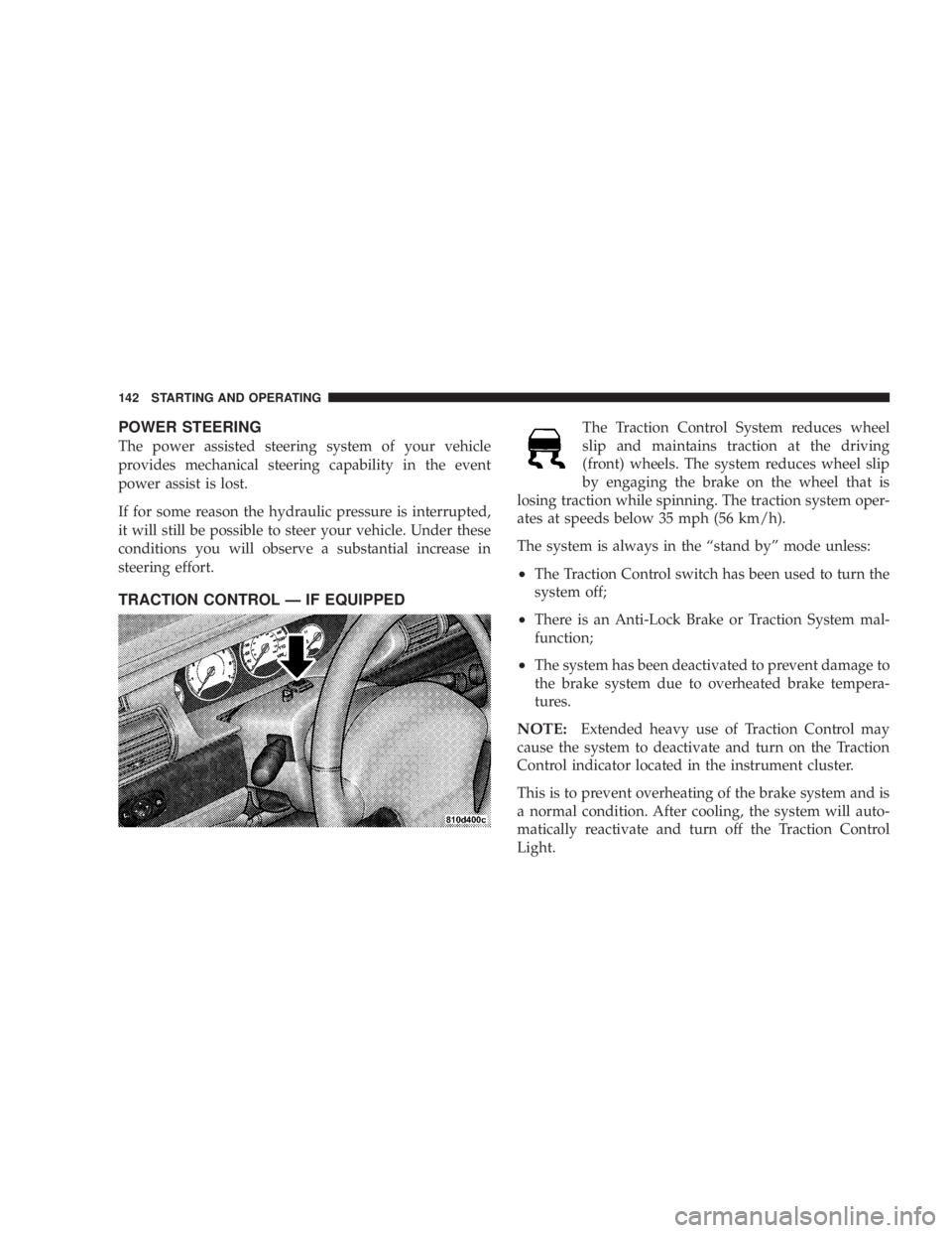
TRACTION CONTROL Ð IF EQUIPPED
The Traction Control System reduces wheel
slip and maintains traction at the driving
(front) wheels. The system reduces wheel slip
by engaging the brake on the wheel that is
losing traction while spinning. The traction system oper-
ates at speeds below 35 mph (56 km/h).
The system is always in the ªstand byº mode unless:
²The Traction Control switch has been used to turn the
system off;
²There is an Anti-Lock Brake or Traction System mal-
function;
²The system has been deactivated to prevent damage to
the brake system due to overheated brake tempera-
tures.
NOTE:Extended heavy use of Traction Control may
cause the system to deactivate and turn on the Traction
Control indicator located in the instrument cluster.
This is to prevent overheating of the brake system and is
a normal condition. After cooling, the system will auto-
matically reactivate and turn off the Traction Control
Light.
142 STARTING AND OPERATING
Page 150 of 273
WARNING!
Overloading of your tire is dangerous. Overloading
can cause tire failure, affect vehicle handling, and
increase your stopping distance. Use tires of the
recommended load capacity for your vehicle. Never
overload them.
TIRESÐGENERAL INFORMATION
Tire Pressure
Proper tire inflation pressure is essential to the safe and
satisfactory operation of your vehicle. Three primary
areas are affected by improper tire pressure:
1. SafetyÐ
WARNING!
Improperly inflated tires are dangerous and can
cause accidents.
²Under inflation increases tire flexing and can
result in tire failure.
²Over inflation reduces a tire's ability to cushion
shock. Objects on the road and chuck holes can cause
damage that results in tire failure.
²Unequal tire pressures can cause steering prob-
lems. You could lose control of your vehicle.
²Over inflated or under inflated tires can affect
vehicle handling and can fail suddenly, resulting in
loss of vehicle control.
²Unequal tire pressures from one side of the vehicle
to the other can cause the vehicle to drift to the right
or left.
Always drive with each tire inflated to the recom-
mended cold tire inflation pressure.
150 STARTING AND OPERATING