Page 280 of 388

WARNING!
When using jumper cables to start a vehicle, follow
procedures exactly and exercise extreme caution.
CAUTION!
Do not try to start your vehicle by pushing or towing.
Vehicles equipped with an automatic transaxle can-
not be started this way. Pushing or towing a vehicle
equipped with a manual transaxle may overheat and
damage the catalytic converter. Also, there is a
greater risk of an accident when a vehicle is being
pushed or towed.
1. Remove any metal jewelry such as watch bands or
bracelets that might make an inadvertent electrical con-
tact.
2. Position the vehicles close enough together so the
booster cables can reach, but be sure the vehicles aren't
touching each other. If they are, it could cause a groundconnection. You wouldn't be able to start your vehicle,
and the bad ground could damage the electrical systems.
CAUTION!
Check the other vehicle. It must have a 12-volt
battery. If the other system isn't 12-volts, both sys-
tems can be damaged.
3. You could be injured if the vehicles move. Set the
parking brake firmly on each vehicle. Put an automatic
transaxle in ªPº (PARK) or a manual transaxle in ªNº
(Neutral). Turn the ignition key to the ªLOCKº position.
WARNING!
Turn the ignition key to the ªLOCKº position on
both vehicles.
Use care to make sure that the cables or your clothes
are never caught by the fan or drive belt. Personal
injury could result.
280 EMERGENCIES
Page 285 of 388

CAUTION!
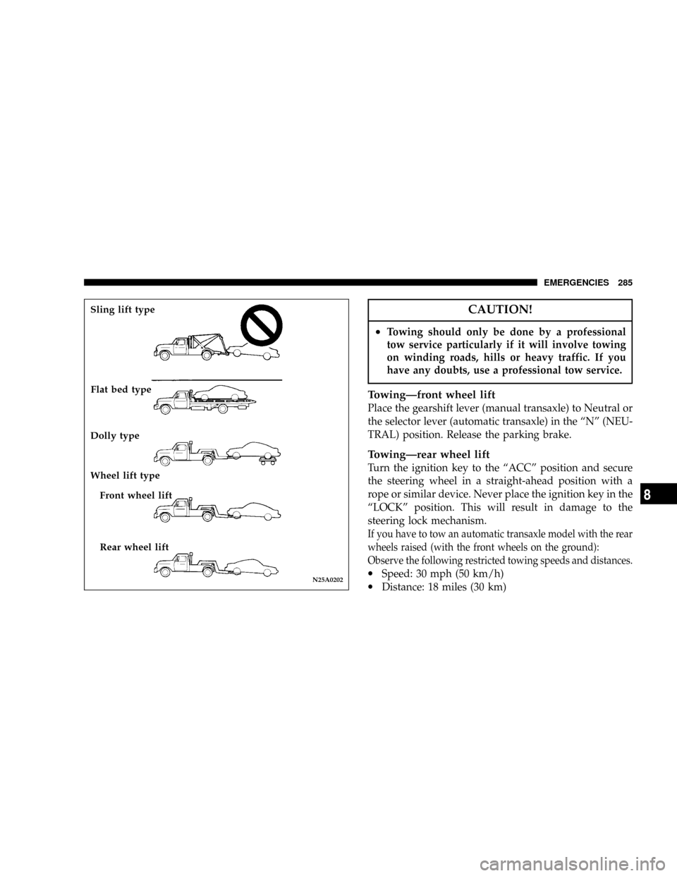
²Towing should only be done by a professional
tow service particularly if it will involve towing
on winding roads, hills or heavy traffic. If you
have any doubts, use a professional tow service.
TowingÐfront wheel lift
Place the gearshift lever (manual transaxle) to Neutral or
the selector lever (automatic transaxle) in the ªNº (NEU-
TRAL) position. Release the parking brake.
TowingÐrear wheel lift
Turn the ignition key to the ªACCº position and secure
the steering wheel in a straight-ahead position with a
rope or similar device. Never place the ignition key in the
ªLOCKº position. This will result in damage to the
steering lock mechanism.
If you have to tow an automatic transaxle model with the rear
wheels raised (with the front wheels on the ground):
Observe the following restricted towing speeds and distances.
·Speed: 30 mph (50 km/h)
·Distance: 18 miles (30 km)N25A0202
Sling lift type
Flat bed type
Dolly type
Wheel lift type
Front wheel lift
Rear wheel lift
EMERGENCIES 285
8
Page 290 of 388
No. Symbol Electrical system Capacity
1
Fuse (+B) 60A
2
Radiator fan motor 50A
3
Anti-lock braking system 60A
4
Ignition switch 40A
5
Electric window controls 30A
6
Fog lights 15A
7Ð Ð Ð
8
Horn 15A
9
Engine control 20A
10
Air conditioning 10A
11
Stop lights 15A
12
ÐÐ
13
Alternator 7.5A
14
Hazard warning flasher 10A
15
Automatic transaxle 20A
16
Headlights high beam (right) 10A
17
Headlights high beam (left) 10A
18
Headlights low beam (right) 10A
19
Headlights low beam (left) 10A
20
Position lights (right) 7.5A
21
Position lights (left) 7.5A
No. Symbol Electrical system Capacity
22
Dome lights 10A
23
Audio 10A
24
Fuel pump 15A
25
Defroster 40A
²Some fuses may not be installed on your vehicle. Fuse
application depends on the vehicle model, specifica-
tions, or options.
7.5A BROWN
10A RED
15A LIGHT BLUE
20A YELLOW
30A GREEN
40A GREEN
50A RED
60A YELLOW
290 EMERGENCIES
Page 291 of 388
Fuse replacement
1. Before replacing a fuse, always turn off the electrical
item concerned and turn the ignition key to the ªLOCKº
position.
2. Remove the fuse cover.
3. Referring to the fuse location diagrams and corre-
sponding tables, check the fuse that relates to the prob-
lem.4. There is a fuse puller in the cover of the instrument
panel (driver 's side). Remove the fuse puller, clamp it on
the fuse you wish to remove, and pull the fuse straight
out from the fuse block. If the fuse is not blown, some-
thing else must be causing the problem; contact an
authorized dealer to have the problem checked.
N29C0020
OKBlown fuseN29C0200
EMERGENCIES 291
8
Page 309 of 388

MAINTENANCE
CONTENTS
mView of engine compartment..............311
mService precautions.....................312
mEmission-control system maintenance.......313
mEmissions Testing......................314
mOnboard Diagnostic System (OBD II)........314
mReplacement Parts......................315
NFuel system (tank, filler tube, connections,
and fuel tank filler cap).................315
NFuel hoses...........................315
NAir cleaner filter......................316
NEvaporative emission control system
(except evaporative emission canister).......316
NSpark plugs..........................317
NIgnition cables........................317NDistributor cap and rotor................317
mGeneral maintenance....................318
NEngine oil and oil filter..................318
mEngine coolant.........................322
NTo check the coolant level................322
NTo add coolant........................322
mBrake fluid...........................323
mClutch fluid (manual transaxle)............324
NTo check the clutch fluid.................324
NTo replace the fluid....................324
mBattery..............................325
NDuring cold weather...................325
9
Page 313 of 388

WARNING!
²The fan may turn on automatically even if the
engine is not running; turn the ignition key to the
ªLOCKº position and remove the key to ensure
safety while you work in the engine compartment.
²Do not smoke, or allow open flames around fuel
or the battery. The fumes are flammable.
²Be extremely cautious when working around the
battery. It contains poisonous and corrosive sulfu-
ric acid.
²Do not get under your vehicle with just the car's
jack supporting it.
Always use properly rated automotive jack
stands.
²Improper handling of components and materials
used in the vehicle can endanger your personal
safety. Consult an authorized dealer if you have
questions.
EMISSION-CONTROL SYSTEM MAINTENANCE
Your vehicle is equipped with an emission-control sys-
tem which satisfies all requirements of the U.S. Environ-
mental Protection Agency. The emission-control system
consists of:
(1) a positive crankcase ventilation system
(2) an evaporative emission-control system
(3) an exhaust emission- control system.
The9Scheduled9maintenance services listed must be
performed at the times or mileages specified to assure the
continued proper functioning of the emission-control
system. These, and all other ªGeneralº maintenance
services included in this manual, should be performed to
provide the best vehicle performance and reliability.
More frequent maintenance may be needed for vehicles
driven under severe operating conditions such as dusty
areas and frequent start and stop driving.
In order to assure the proper function of the emission-
control system, it is recommended that you have your
vehicle inspected and maintained by an authorized
dealer in accordance with the schedule in this manual.
Inspection and service should also be performed any
time a malfunction is suspected.
MAINTENANCE 313
9
Page 315 of 388

If the light is flashing, severe catalytic converter damage
and power loss will soon occur. Immediate service is
required.
If the gas cap is not tightened properly, the light may
come on. Be sure the gas cap is tightened every time you
add fuel. Tighten the cap until you hear it ªclick.º
REPLACEMENT PARTS
Use of genuine Mopar parts for normal/scheduled main-
tenance and repairs is highly recommended to insure the
designed performance. Damage or failures caused by the
use of non-Mopar parts for maintenance and repairs will
not be covered by the manufacturers warranty.
Fuel system (tank, filler tube, connections, and
fuel tank filler cap)
Check periodically for damage or leakage in the fuel lines
and connections, and check for damage and looseness of
the fuel tank filler tube cap. Particular attention should be
paid to examining those fuel lines nearest to high heat
sources such as the exhaust manifold.
WARNING!
If you see a fuel leak or if you smell fuel, do not
operate the vehicle. Any spark (including from the
ignition ), flame or smoking material could cause an
explosion or fire. Call an authorized dealer for
assistance.
Fuel hoses
Inspect the surfaces of hoses for evidence of heat and
mechanical damage, hard and brittle rubber, cracking,
tears, cuts and abrasions. Particular attention should be
paid to examining those hose surfaces nearest to high
heat sources such as the exhaust manifold. Inspect all
hose connections, such as clamps and couplings, to make
sure they are secure and that no leaks exist. If there is any
evidence of deterioration or damage, hoses should be
replaced immediately.
MAINTENANCE 315
9
Page 317 of 388

Spark plugs
Spark plugs must fire properly to assure proper engine
performance and emission-control.
Do not reuse spark plugs by cleaning or regapping. Spark
plugs should be replaced at the mileage specified on the
scheduled maintenance chart.
Your vehicle may be equipped with standard type spark
plugs or iridium tipped ones. Iridium tipped spark plugs
are identified by blue marks on the ceramic. They do notrequire replacement as frequently as the conventional
type spark plug and are designed to last much longer.
NOTE: Use the recommended or equivalent spark plugs
listed under ªEngine specificationsº on page 367.
Use of non-recommended plugs will cause engine dam-
age, loss of performance or radio noise.
Ignition cables
The ignition cables should be kept clean, properly con-
nected, and fully seated. Terminals should be fully seated
and should not be removed from the distributor or coil
towers unless they are damaged or cable testing indicates
high resistance or broken insulation. Cracked, damaged,
or faulty cables must be replaced.
Distributor cap and rotor
Check the distributor cap and rotor to maintain proper
function and good emission control.
P15A0340
MAINTENANCE 317
9