Page 70 of 300

when the switch is pressed in, when the headlight switch
is rotated to the OFF position or the high beam is
selected.
CARGO Light Ð If Equipped
The cargo lights are turned on by rotating the dimmer
control to the optional fully upward position. The interior
lights will also turn on when the cargo lights are on. The
cargo lights will also turn on for 30 seconds when a key
fob Unlock is pressed, as part of the illuminated entry
feature.
MULTIFUNCTION CONTROL LEVER
The multifunction control lever is located on the left side
of the steering column.
Turn Signals
Move the lever up or down to signal a right-hand or
left-hand turn.
The arrow on either side of the instrument cluster flashes
to indicate the direction of the turn, and proper operation
of the front and rear turn signal lights. If either indicator
flashes at a faster rate, check for a defective outside lightbulb. If an indicator fails to light when the lever is
moved, it would suggest that the fuse or indicator bulb is
defective.
You can signal a lane change by moving the lever
partially up or down.
Passing Light
You can signal another vehicle with your headlights by
partially pulling the multifunction lever toward the steer-
ing wheel. This will cause the high beam headlights to
turn on until the lever is released.
70 UNDERSTANDING THE FEATURES OF YOUR VEHICLE
Page 181 of 300

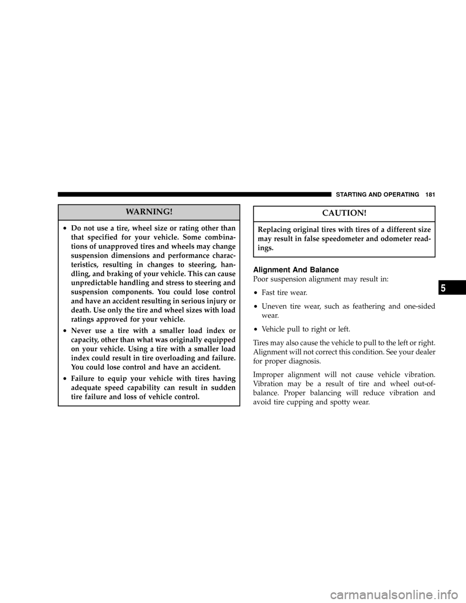
WARNING!
²Do not use a tire, wheel size or rating other than
that specified for your vehicle. Some combina-
tions of unapproved tires and wheels may change
suspension dimensions and performance charac-
teristics, resulting in changes to steering, han-
dling, and braking of your vehicle. This can cause
unpredictable handling and stress to steering and
suspension components. You could lose control
and have an accident resulting in serious injury or
death. Use only the tire and wheel sizes with load
ratings approved for your vehicle.
²Never use a tire with a smaller load index or
capacity, other than what was originally equipped
on your vehicle. Using a tire with a smaller load
index could result in tire overloading and failure.
You could lose control and have an accident.
²Failure to equip your vehicle with tires having
adequate speed capability can result in sudden
tire failure and loss of vehicle control.
CAUTION!
Replacing original tires with tires of a different size
may result in false speedometer and odometer read-
ings.
Alignment And Balance
Poor suspension alignment may result in:
²Fast tire wear.
²Uneven tire wear, such as feathering and one-sided
wear.
²Vehicle pull to right or left.
Tires may also cause the vehicle to pull to the left or right.
Alignment will not correct this condition. See your dealer
for proper diagnosis.
Improper alignment will not cause vehicle vibration.
Vibration may be a result of tire and wheel out-of-
balance. Proper balancing will reduce vibration and
avoid tire cupping and spotty wear.
STARTING AND OPERATING 181
5
Page 212 of 300

WARNING!
Do not attempt to change a tire on the side of the
vehicle close to moving traffic. Pull far enough off
the road to avoid the danger of being hit when
operating the jack or changing the wheel.
²Turn on the Hazard Warning Flasher.
²Block both the front and rear
of the wheel diagonally oppo-
site the jacking position. For
example, if the right front
wheel is being changed, block
the left rear wheel.
²Passengers should not remain in the vehicle when the
vehicle is being jacked.
Instructions
1. Remove the spare wheel, jack, and tools from storage.
2. Remove wheel center cap using the spade end of the
wheel wrench.
3. Using the wheel wrench, loosen, but do not remove,
the wheel nuts by turning them counterclockwise one
turn while the wheel is still on the ground.
4. When changing a front wheel, place the jack under the
frame rail behind the wheel. Locate the jack as far
forward as possible on the straight part of the frame.
Make sure that the upstanding tab of the jack contacts the
vertical side of the frame. Operate the jack using the jack
drive tube and the wheel wrenchÐ the tube extension,
may be used but is not required.
When changing a rear wheel, assemble the jack drive
tube to the jack and connect the drive tube to the
extension tube. Place the jack under the axle between the
spring and the shock absorber with the drive tubes
extending to the rear. Connect the jack tube extension and
wheel wrench.
212 WHAT TO DO IN EMERGENCIES