2004 DAEWOO NUBIRA air conditioning
[x] Cancel search: air conditioningPage 2015 of 2643

MANUAL CONTROL HEATING, VENTILATION AND AIR CONDITIONING SYSTEM 7B – 13
DAEWOO V–121 BL4
StepNo Yes Value(s) Action
81. Check for a knocking noise from the A/C com-
pressor.
2. Cycle the A/C compressor ON and OFF in or-
der to verify the source of the noise.
Do you hear a loud knocking noise?–Go to Step 9Go to Step 13
91. Recover the A/C system refrigerant.
2. Replace the A/C compressor.
3. Evacuate and recharge the A/C system.
4. Check the A/C system for leaks.
Is the compressor running normally?–Go to Step 13–
101. Turn the ignition switch to LOCK.
2. Disconnect the A/C compressor clutch coil con-
nector.
3. Connect a jumper wire from ground to one A/C
compressor clutch coil terminal.
4. Connect a fused jumper wire from the positive
battery terminal to the other A/C compressor
clutch coil terminal.
Does the A/C clutch engage?–Go to Step 11Go to Step 12
11Repair the electrical circuit to the A/C compressor
clutch coil.
Does the A/C clutch engage?–Go to Step 8–
12Replace the A/C compressor clutch coil.
Does the A/C clutch engage?–Go to Step 8–
131. Close all of the vehicle’s windows and doors.
2. Set the A/C controls to the following positions:
S The A/C switch to the ON position.
S The fresh air control switch to fresh air.
S The blower motor to 4.
S The temperature to full cold.
3. Start the engine and allow it to run at idle for 5
minutes.
4. Feel the evaporator inlet and outlet pipes.
Is there a noticeable difference in the temperature of
the evaporator inlet and outlet pipes?–Go to Step 15Go to Step 14
141. Turn the ignition switch to LOCK.
2. Recover the A/C system refrigerant.
3. Examine the high–pressure pipe for an ob-
struction.
4. Examine the expansion valve for an obstruction
or a malfunction.
5. Repair the obstruction or replace the expansion
valve as needed.
6. Evacuate and recharge the A/C system.
7. Check the A/C system for leaks.
8. Note the discharge air temperature with the
A/C ON.
Is the discharge temperature normal?At least 7°C
(12°F) below
ambient air
temperatureGo to Step 15Go to Step 13
Page 2016 of 2643

7B – 14IMANUAL CONTROL HEATING, VENTILATION AND AIR CONDITIONING SYSTEM
DAEWOO V–121 BL4
StepNo Yes Value(s) Action
151. Record the low– and the high–side pressures
after the A/C system has been operating for 5
minutes or more with the engine cooling fan
ON.
2. Locate the intersection of the low– and the high
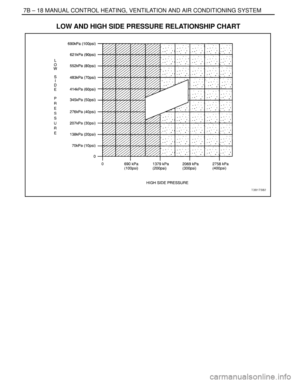
side pressures. Refer to ”Low– and High–Side
Pressure Relationship Chart” in this section.
Do the low– and the high–side pressures intersect
in the white area of the chart?–System OKGo to Step 16
16Check the high– and the low–side pressures.
Do the low– and the high–side pressures intersect
in the grey area of the chart?–Go to Step 17Go to Step 20
17Feel the liquid pipe between the condenser and the
expansion valve.
Is the pipe cold?–Go to Step 18Go to Step 19
181. Examine the condenser for any restriction of
the airflow.
2. Check the cooling fans for proper operation.
3. Remove the restriction or repair the fans, as
required.
Is the pipe temperature normal now?At least 7°C
(12°F) below
ambient air
temperatureGo to Step 13–
191. Recover, evacuate, and recharge the A/C sys-
tem.
2. Check the A/C system for leaks.
Is the system free from leaks?–Go to Step 13–
20Observe the readings on the pressure gauges.
Are the A/C compressor high– and the low–side
pressures within the specified value of each other?207 kPa
(30 psi)Go to Step 21Go to Step 26
211. Run the engine at 3,000 rpm.
2. Set the A/C controls to the following positions:
S The A/C switch to the ON.
S The fresh air control switch to fresh air.
S The blower motor to 4.
S The temperature to full cold.
3. Close all of the vehicle’s windows and doors.
4. Turn the A/C switch ON and OFF every 20
seconds for 3 minutes.
Are the A/C compressor high– and the low–side
pressures within the specified value of each other?207 kPa
(30 psi)Go to Step 22Go to Step 13
22Observe the pressure rise on both gauges and the
temperatures of both the compressor suction pipe
and the discharge pipe.
Is the pressure rise on both gauges slow and the
suction pipe warm with the discharge pipe very hot?–Go to Step 25Go to Step 23
231. Turn the ignition switch to LOCK.
2. Make sure the compressor clutch is disen-
gaged.
3. Attempt to turn the clutch driver (not the
pulley).
Can you turn the clutch driver freely by hand?–Go to Step 25Go to Step 24
Page 2017 of 2643

MANUAL CONTROL HEATING, VENTILATION AND AIR CONDITIONING SYSTEM 7B – 15
DAEWOO V–121 BL4
StepNo Yes Value(s) Action
241. Start the engine.
2. Observe the low–side pressure gauge while
running the engine between 3,000 and 3,800
rpm.
Does the low–side pressure rise rapidly?–Go to Step 32Go to Step 25
251. Recover the A/C system refrigerant.
2. Replace the A/C compressor.
3. Evacuate and recharge the A/C system.
Is the compressor functioning normally?–Go to Step 13–
26Check the low–side pressure.
Is the low–side pressure within the specified value?172–241 kPa
(25–35 psi)Go to Step 27Go to Step 32
27Feel the high–side pipe leading up to the expansion
valve connecting block.
Is the pipe cold before the connecting block?–Go to Step 28Go to Step 29
281. Check for a restriction in the high–side pipe
before the expansion valve.
2. Repair or replace the high–side pipe.
Is the pipe performing normally?–Go to Step 13–
29Add the specified amount of refrigerant to the A/C
system.
Does the cooling performance improve?0.40 kg
(14 ounces)Go to Step 30Go to Step 31
301. Check the A/C system for leaks.
2. Repair any refrigerant leaks, as needed.
3. Evacuate and recharge the A/C system.
4. Check the A/C system for leaks.
Is the system free from leaks?–Go to Step 13–
311. Recover the refrigerant.
2. Check the expansion valve for obstructions.
3. Repair or replace the expansion valve, as re-
quired.
4. Evacuate and recharge the system.
5. Check the A/C system for leaks.
Is the system free from leaks?–Go to Step 13–
321. Run the engine for 5 minutes at 2,000 rpm.
2. Set the A/C controls to the following positions:
S The A/C switch to the ON position.
S The fresh air control switch to recirculate
(indicator lamp ON).
S The blower motor to 1.
S The temperature to full cold.
3. Close all of the vehicle’s windows and doors.
4. Open the vehicle hood.
Is the low–side pressure within the specified value?172–241 kPa
(25–35 psi)Go to Step 13Go to Step 33
331. Recover the A/C system refrigerant.
2. Replace the A/C compressor control valve.
3. Evacuate and recharge the A/C system.
4. Check the A/C system for leaks.
Is the system free from leaks?–Go to Step 13–
Page 2018 of 2643

7B – 16IMANUAL CONTROL HEATING, VENTILATION AND AIR CONDITIONING SYSTEM
DAEWOO V–121 BL4
SYMPTOM DIAGNOSIS
PRESSURE TEST CHART (R–134A SYSTEM)
Test ResultsRelated SymptiomsProbable CauseRemedy
Discharge (high)
pressure abnormally
highAfter stopping the compres-
sor, the pressure drops
about 299 kPa (28 psig)
quickly, then falls gradually.Air in the system.Recover, evacuate and re-
charge the system with the
specified amount of refrig-
erant.
The condenser is exces-
sively hot.Excessive refrigerant in the sys-
tem.Recover, evacuate and re-
charge the system with the
specified amount of refrig-
erant.
Reduced or no airflow
through the condenser.Condenser or the radiator fins are
clogged.Clean the condenser or the
radiator fins.
Condenser or the radiator fan is
not working properly.Check the voltage and the
fan rpm.
Check the fan direction.
Line to the condenser is ex-
cessively hot.Restricted flow of refrigerant in
the system.Locate and repair the re-
striction.
Discharge pressure
abnormally lowThe condenser is not hot.Insufficient refrigerant in the sys-
tem.Check the system for a
leak.
Charge the system.
High and low pressures are
balanced soon after stop-
ping the compressor.Faulty compressor pressure relief
valve.Repair or replace the com-
pressor.
Low–side pressure is high-
er than normal.Faulty compressor seal.
The outlet of the expansion
valve is not frosted.Faulty expansion valve.Replace the expansion
valve.
Low pressure gauge indi-
cates vacuum.Moisture in the system.Recover, evacuate, and re-
charge the system.
Suction (low) pres-
sure abnormally lowCondenser is not hot.Insufficient refrigerant in the sys-
tem.Repair the leaks.
Recover, evacuate, and re-
charge the system.
The expansion valve is not
frosted and the lowpressure
line is not cold.Faulty expansion valve.Replace the expansion
valve.
Low–Pressure gauge indi-
cates a vacuum.Frozen expansion valve.
Discharge temperature is
low and the airflow from the
vents is restricted.Evaporator is frozen.Clear the restricted evapo-
rator case drain.
The expansion valve is
frosted.Expansion valve is clogged.Clean or replace the expan-
sion valve.
The receiver–dryer outlet is
cool and the inlet is warm.Receiver–dryer is clogged.Replace the receiver–dryer.
Suction pressure ab-
normally highLow–pressure hose and
check joint are cooler than
the temperature around the
evaporator.Expansion valve is opened for too
long.Replace the expansion
valve.
Capillary tube is loose.
Page 2019 of 2643

MANUAL CONTROL HEATING, VENTILATION AND AIR CONDITIONING SYSTEM 7B – 17
DAEWOO V–121 BL4
Test ResultsRemedy Probable Cause Related Symptioms
Suction pressure ab-
normally highSuction pressure is lowered
when the condenser is
cooled by water.Excessive refrigerant in the sys-
tem.Recover, evacuate, and re-
charge the system.
High and low pressure are
equalized as soon as the
compressor is stopped and
both gauges fluctuate while
the compressor is running.Faulty gasket.Repair or replace the com-
pressor.
Faulty high–pressure valve. (V5
compressor only)
Foreign particles stuck in the
high–pressure valve. (V5 com-
pressor only)
Suction and dis-
charge pressure ab-
ll hi h
Reduced airflow through
the condenser.Clogged condenser or radiator
fins.Clean the condenser and
the radiator.
g
normally highRadiator cooling fans working im-
properly.Check the voltage and the
radiator cooling fan rpm.
Check the fan direction.
Condenser is excessively
hot.Excessive refrigerant in the sys-
tem.Recover, evacuate, and re-
charge the system.
Suction and dis-
charge pressure ab-
normally lowLow–pressure hose and
metal end areas are cooler
than the evaporator.Clogged or kinked low–pressure
hose.Repair or replace the low–
pressure hose.
Temperature around the ex-
pansion valve is low
compared to that around
the receiver–dryer.Clogged high–pressure line.Repair or replace the high–
pressure line.
Refrigerant leaksThe compressor clutch is
dirty.Leaking compressor shaft seal.Repair or replace the com-
pressor.
The compressor bolts are
dirty.Leaking around a compressor
housing bolt.Tighten the bolt(s) or re-
place the compressor.
The compressor gasket is
wet with oil.Leaking compressor gasket.Repair or replace the com-
pressor.
Page 2020 of 2643
7B – 18IMANUAL CONTROL HEATING, VENTILATION AND AIR CONDITIONING SYSTEM
DAEWOO V–121 BL4
LOW AND HIGH SIDE PRESSURE RELATIONSHIP CHART
Page 2021 of 2643

MANUAL CONTROL HEATING, VENTILATION AND AIR CONDITIONING SYSTEM 7B – 19
DAEWOO V–121 BL4
MAINTENANCE AND REPAIR
ON–VEHICLE SERVICE
GENERAL A/C SYSTEM SERVICE PROCEDURES
O–RING REPLACEMENT
Important : Even though O–rings may look identical, it is
extremely important that only recommended service re-
placement air conditioning O–rings be used or excessive
leakage of refrigerant may occur.
Important : Always slip the O–ring onto the flange tube to
ensure proper locating and sealing.
Install new Daewoo–approved service replacement air
conditioning (A/C) O–rings whenever a joint or a fitting is
disassembled, except when the O–rings are provided on
new components.
When replacing O–rings on an A/C component or a joint
connection, the fitting design should be identified to en-
sure installation of the correct air conditioning service re-
placement O–ring. Some joint connections and compo-
nents will implement a ”captured” O–ring design fitting that
uses a groove to retain the O–ring. Others do not have a
groove and use a ”non–captured” or ”standard” O–ring.
Assembly and tightening procedures are the same for
both designs, but the O–rings are different.
Notice : Before installation, verify that both O–rings and
fittings have not been nicked or deformed. Deformed or
nicked parts must be replaced. Failure to use the proper
service replacement parts and procedures may result in
excessive refrigerant leakage.
HANDLING REFRIGERANT
CAUTION : Always work in a well–ventilated area and
avoid breathing any refrigerant fumes. If you have dif-
ficulty with breathing, seek medical attention immedi-
ately. If refrigerant comes in contact with any part of
your body, flush the exposed area with water. If a rash
or pain develops, seek medical attention.
Air conditioning systems contain refrigerant. This is a
chemical mixture which requires special handling proce-
dures to avoid personal injury.
Always wear goggles and wrap a clean cloth around the
fittings, the valves and the connections when performing
work that involves opening the refrigerant system. Do not
weld or steam clean on or near any vehicle–installed air
conditioning lines or components.
All refrigerant drums are shipped with a heavy metal screw
cap. The purpose of the cap is to protect the valve and the
safety plug from damage. It is good practice to replace the
cap after each use of the drum.If it is necessary to transport or carry any container of re-
frigerant in a vehicle, do not carry it in the passenger
compartment.
HANDLING OF REFRIGERANT LINES
AND FITTINGS
Notice : Using too low or too high torque when tightening
a fitting can result in loose joints or deformed joint parts.
Both conditions can result in refrigerant leakage.
S Keep all metal tubing lines free of dents or kinks.
Any line restrictions will cause the loss of system
capacity.
S Never bend a flexible hose line to a radius of less
than four times the diameter of the hose.
S Never allow a flexible hose line to come within 65
mm (2–1/2 inches) of the exhaust manifold.
S Inspect flexible hose lines regularly for leaks or
brittleness.
S Replace flexible hose lines with new lines if you find
signs of deterioration or leaking.
S Discharge all refrigerant of the refrigeration system
before disconnecting any fitting in the refrigeration
system.
S Proceed very cautiously regardless of the gauge
readings.
CAUTION : Keep your face and your hands away from
the fitting so that you will not be injured if there hap-
pens to be liquid refrigerant in the line.
S Open the fittings very slowly.
S If you notice pressure when you loosen a fitting,
allow the pressure to bleed off as described under
”Discharging, Adding Oil, Evacuating, and Charging
Procedures for A/C System” in this section.
S Cap or tape any refrigerant line immediately after it
is opened. This will prevent the entrance of mois-
ture and dirt, which can cause internal compressor
wear or plugged lines in the condenser, the evapo-
rator core, the expansion valve, or the compressor
inlet screens.
Important : Use two proper wrenches to connect the O–
ring fittings.
S Back up the opposing fitting to prevent distortion of
the connecting lines or the components.
S Back up both the swagged fitting on the flexible
hose connections and the coupling to which it is
attached with two wrenches to prevent turning the
fitting and damaging the ground seat.
S Keep the O–rings and the seats in perfect condi-
tion. A burr or a piece of dirt may cause a refriger-
ant leak.
Page 2022 of 2643

7B – 20IMANUAL CONTROL HEATING, VENTILATION AND AIR CONDITIONING SYSTEM
DAEWOO V–121 BL4
S Dip new O–rings in clean polyalkaline glycol refrig-
erant oil before installation.
MAINTAINING CHEMICAL STABILITY
IN THE REFRIGERATION SYSTEM
The efficient operation and the life of the air conditioning
(A/C) system is dependent upon the chemical stability of
the refrigeration system. When foreign materials, such as
dirt, air, or moisture, contaminate the refrigeration system,
they will change the stability of the refrigerant and the poly-
alkaline glycol (PAG) compressor oil. They will also affect
the pressure–temperature relationship, reduce efficient
operation, and can possibly cause interior corrosion and
abnormal wear of moving parts.
Observe the following practices to ensure chemical stabil-
ity in the system:
S Wipe away dirt or oil at and near any connection
before opening that connection. This will reduce the
chance of dirt entering the system.
S Cap, plug, or tape both sides of a connection as
soon as possible after opening the connection. This
will prevent the entry of dirt, foreign material, and
moisture.
S Keep all tools clean and dry, including the manifold
gauge set and all replacement parts.
S Use a clean and dry transfer device and container
to add polyalkaline glycol refrigerant oil. This will
ensure that the oil remains as moisture–free as
possible. Refer to ”Discharging, Adding Oil, Eva-
cuating, and Charging Procedures for A/C System”
in this section.
S Have everything you need ready to allow you to
perform all operations quickly when opening an A/C
system. Do not leave the A/C system open any lon-
ger than necessary.
S Evacuate and recharge any A/C system that has
been opened. Refer to ”Discharging, Adding Oil,
Evacuating, and Charging Procedures for A/C Sys-
tem” in this section for the instructions to perform
this procedure properly.
All service parts are dehydrated and sealed before ship-
ping. They should remain sealed until just before making
connections. All the parts should be at room temperature
before uncapping. This prevents condensation of mois-
ture from the air from entering the system. Reseal all parts
as soon as possible.
DISCHARGING, ADDING OIL,
EVACUATING, AND CHARGING
PROCEDURES FOR A/C SYSTEM
CAUTION : Use only refillable refrigerant tanks that
are authorized for the charging station being used.
The use of other tanks may cause personal injury or
void the warranty. Refer to the manufacturer’s in-
structions for the charging station.CAUTION : To avoid personal injury, always wear
goggles and gloves when performing work that in-
volves opening the refrigeration system.
A charging station discharges, evacuates, and recharges
an air–conditioning (A/C) system with one hookup. Filter-
ing the refrigerant during the recovery cycle together with
filtering during the evacuation cycle ensures a supply of
clean, dry refrigerant for A/C system charging.
S Never use the R–134a charging station on a sys-
tem charged with R–12. The refrigerants and the
oils from each system are not compatible with
those from the other system and must never be
mixed, even in the smallest amount. Mixing refriger-
ant residue will damage the equipment.
S Never use adapters which convert from one size
fitting to another. Such use allows contamination,
which may cause system failure.
Charging Station Setup and Maintenance
There are many charging stations available. All perform
the various tasks required to discharge the system and re-
cover refrigerant, evacuate the system, add a measured
amount of oil, and recharge an A/C system with a mea-
sured amount of refrigerant. Refer to the manufacturer’s
instructions for all initial setup procedures and all mainte-
nance procedures.
Control Panel Functions
A charging station will have controls and indicators to allow
the operator to control and monitor the operation in prog-
ress. Refer to the manufacturer’s instructions for details.
These can be expected to include the following:
1. Main Power Switch
S Supplies electrical power to the control panel.
2. Display
S Shows the time programmed for vacuum.
S Shows the weight of the refrigerant programmed
for recharging.
S Refer to the manufacturer’s instructions for de-
tailed programming information.
3. Low–Side Manifold Gauge
S Shows the system’s low–side pressure.
4. High–Side Manifold Gauge
S Shows the system’s high–side pressure.
5. Controls Panel
S Controls the various operating functions.
6. Low–Side Valve
S Connects the low side of the A/C system to the
unit.
7. Moisture Indicator
S Shows whether the refrigerant is wet or dry.
8. High–Side Valve
S Connects the high side of the A/C system to the
unit.