Page 1320 of 2643
5–160WELECTRICAL WIRING DIAGRAMS
2) TEMPERATURE GAUGE, TACHOMETER, FUEL GAUGE, ODDOMETER, SPEEDOMETER &
FUEL WARNING LAMP CIRCUIT: SIRIUS D4a. CONNECTOR INFORMATION
CONNECTOR(NO.)
(PIN NO. COLOR)
CONNECTING, WIRING HARNESSCONNECTOR POSITION
C102 (11 Pin, White)Body � Engine Fuse BlockEngine Fuse Block
C108 (24 Pin, Black)Body � EngineLeft Engine Fuse Block
C201 (76 Pin, Black)I.P � I.P Fuse BlockI.P Fuse Block
C202 (89 Pin, White)I.P � BodyLeft CO–Driver Leg Room
S202 (Black)I.PBehind Cluster
G201I.PLeft I.P Fuse Block
G302BodyBelow Left C Pillar
b. CONNECTOR IDENTIFICATION SYMBOL & PIN NUMBER POSITION
J3B1P059
Page 1330 of 2643
5–170WELECTRICAL WIRING DIAGRAMS
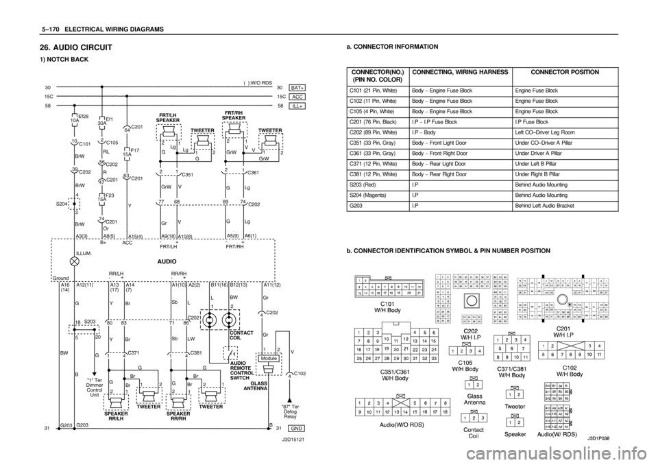
26. AUDIO CIRCUIT
1) NOTCH BACK
a. CONNECTOR INFORMATION
CONNECTOR(NO.)
(PIN NO. COLOR)
CONNECTING, WIRING HARNESSCONNECTOR POSITION
C101 (21 Pin, White)Body � Engine Fuse BlockEngine Fuse Block
C102 (11 Pin, White)Body � Engine Fuse BlockEngine Fuse Block
C105 (4 Pin, White)Body � Engine Fuse BlockEngine Fuse Block
C201 (76 Pin, Black)I.P � I.P Fuse BlockI.P Fuse Block
C202 (89 Pin, White)I.P � BodyLeft CO–Driver Leg Room
C351 (33 Pin, Gray)Body � Front Light DoorUnder CO–Driver A Pillar
C361 (33 Pin, Gray)Body � Front Right DoorUnder Driver A Pillar
C371 (12 Pin, White)Body � Rear Light DoorUnder Left B Pillar
C381 (12 Pin, White)Body � Rear Right DoorUnder Right B Pillar
S203 (Red)I.PBehind Audio Mounting
S204 (Magenta)I.PBehind Audio Mounting
G203I.PBehind Left Audio Bracket
b. CONNECTOR IDENTIFICATION SYMBOL & PIN NUMBER POSITION
Page 1332 of 2643
 HATCH BACKa. CONNECTOR INFORMATION
CONNECTOR(NO.)
(PIN NO. COLOR)
CONNECTING, WIRING HARNESSCONNECTOR POSITION
C101 (21 Pin, White)Body � Engine Fuse BlockEngine")
5–172WELECTRICAL WIRING DIAGRAMS
2) HATCH BACKa. CONNECTOR INFORMATION
CONNECTOR(NO.)
(PIN NO. COLOR)
CONNECTING, WIRING HARNESSCONNECTOR POSITION
C101 (21 Pin, White)Body � Engine Fuse BlockEngine Fuse Block
C102 (11 Pin, White)Body � Engine Fuse BlockEngine Fuse Block
C105 (4 Pin, White)Body � Engine Fuse BlockEngine Fuse Block
C201 (76 Pin, Black)I.P � I.P Fuse BlockI.P Fuse Block
C202 (89 Pin, White)I.P � BodyLeft CO–Driver Leg Room
C204 (8 Pin, White)Roof – Body (W/O Rain Sensor)Left CO�Driver Leg Room
C204 (14 Pin, White)Roof – Body (W/ Rain Sensor)Left CO�Driver Leg Room
C351 (33 Pin, Gray)Body � Front Light DoorUnder CO–Driver A Pillar
C361 (33 Pin, Gray)Body � Front Right DoorUnder Driver A Pillar
C371 (12 Pin, White)Body � Rear Light DoorUnder Left B Pillar
C381 (12 Pin, White)Body � Rear Right DoorUnder Right B Pillar
S203 (Red)I.PBehind Audio Mounting
S204 (Magenta)I.PBehind Audio Mounting
G203I.PBehind Left Audio Bracket
b. CONNECTOR IDENTIFICATION SYMBOL & PIN NUMBER POSITION
Page 1340 of 2643
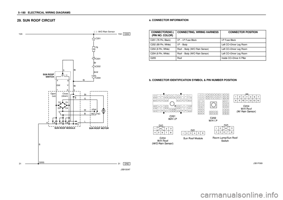
5–180WELECTRICAL WIRING DIAGRAMS
29. SUN ROOF CIRCUITa. CONNECTOR INFORMATION
CONNECTOR(NO.)
(PIN NO. COLOR)
CONNECTING, WIRING HARNESSCONNECTOR POSITION
C201 (76 Pin, Black)I.P � I.P Fuse BlockI.P Fuse Block
C202 (89 Pin, White)I.P � BodyLeft CO–Driver Leg Room
C204 (8 Pin, White)Roof � Body (W/O Rain Sensor)Left CO–Driver Leg Room
C204 (8 Pin, White)Roof � Body (W/O Rain Sensor)Left CO–Driver Leg Room
G205RoofInside CO–Driver A Pillar
b. CONNECTOR IDENTIFICATION SYMBOL & PIN NUMBER POSITION
J3B1P069
Page 1344 of 2643
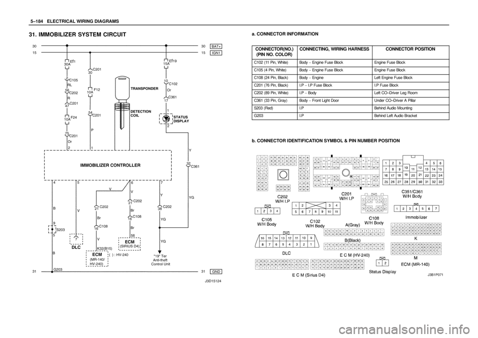
5–184WELECTRICAL WIRING DIAGRAMS
31. IMMOBILIZER SYSTEM CIRCUITa. CONNECTOR INFORMATION
CONNECTOR(NO.)
(PIN NO. COLOR)
CONNECTING, WIRING HARNESSCONNECTOR POSITION
C102 (11 Pin, White)Body � Engine Fuse BlockEngine Fuse Block
C105 (4 Pin, White)Body � Engine Fuse BlockEngine Fuse Block
C108 (24 Pin, Black)Body � EngineLeft Engine Fuse Block
C201 (76 Pin, Black)I.P � I.P Fuse BlockI.P Fuse Block
C202 (89 Pin, White)I.P � BodyLeft CO–Driver Leg Room
C361 (33 Pin, Gray)Body � Front Light DoorUnder CO–Driver A Pillar
S203 (Red)I.PBehind Audio Mounting
G203I.PBehind Left Audio Bracket
b. CONNECTOR IDENTIFICATION SYMBOL & PIN NUMBER POSITION
J3B1P071
Page 1346 of 2643
 NOTCH BACK
a. CONNECTOR INFORMATION
CONNECTOR(NO.)
(PIN NO. COLOR)
CONNECTING, WIRING HARNESSCONNECTOR POSITION
C102 (11 Pin")
5–186WELECTRICAL WIRING DIAGRAMS
32. ANTI THEFT CONTROL SYSTEM CIRCUIT
1) NOTCH BACK
a. CONNECTOR INFORMATION
CONNECTOR(NO.)
(PIN NO. COLOR)
CONNECTING, WIRING HARNESSCONNECTOR POSITION
C102 (11 Pin, White)Body � Engine Fuse BlockEngine Fuse Block
C104 (24 Pin, White)Front � Engine Fuse BlockEngine Fuse Block
C105 (4 Pin, White)Body � Engine Fuse BlockEngine Fuse Block
C113 (16 Pin, Black)Body � FrontBehind ECM Bracket
C201 (76 Pin, Black)I.P � I.P Fuse BlockI.P Fuse Block
C202 (89 Pin, White)I.P � BodyLeft CO–Driver Leg Room
C351 (33 Pin, Gray)Body � Front Light DoorUnder CO–Driver A Pillar
C361 (33 Pin, Gray)Body � Front Right DoorUnder Driver A Pillar
C402 (8 Pin, White)Trunk LID � BodyInside Right Trunk Side Cover
S202 (Black)I.PBehind Cluster
S301 (Blue)BodyLeft CO–Driver Leg Room
S302 (Brown)BodyLeft CO–Driver Leg Room
G301BodyBelow Driver Cross Member Floor Panel
G302BodyBelow Left C Pillar
G303BodyBelow Left CO–Driver Leg Room
b. CONNECTOR IDENTIFICATION SYMBOL & PIN NUMBER POSITION
Page 1348 of 2643
 HATCH BACKa. CONNECTOR INFORMATION
CONNECTOR(NO.)
(PIN NO. COLOR)
CONNECTING, WIRING HARNESSCONNECTOR POSITION
C102 (11 Pin, White)Body � Engine Fuse BlockEngine")
5–188WELECTRICAL WIRING DIAGRAMS
2) HATCH BACKa. CONNECTOR INFORMATION
CONNECTOR(NO.)
(PIN NO. COLOR)
CONNECTING, WIRING HARNESSCONNECTOR POSITION
C102 (11 Pin, White)Body � Engine Fuse BlockEngine Fuse Block
C104 (24 Pin, White)Front � Engine Fuse BlockEngine Fuse Block
C105 (4 Pin, White)Body � Engine Fuse BlockEngine Fuse Block
C113 (16 Pin, Black)Body � FrontBehind ECM Bracket
C201 (76 Pin, Black)I.P � I.P Fuse BlockI.P Fuse Block
C202 (89 Pin, White)I.P � BodyLeft CO–Driver Leg Room
C351 (33 Pin, Gray)Body � Front Light DoorUnder CO–Driver A Pillar
C361 (33 Pin, Gray)Body � Front Right DoorUnder Driver A Pillar
C404 (8 Pin, White)T/Gate. EXT. � BodyInside Left C Pillar
C405 (8 Pin, White)T/Gate. EXT. � T/GateBeside Left Rear Wiper Motor
C406 (6 Pin, White)T/Gate. EXT. � T/GateBeside Left Rear Wiper Motor
S202 (Black)I.PBehind Cluster
S301 (Blue)BodyLeft CO–Driver Leg Room
S302 (Brown)BodyLeft CO–Driver Leg Room
G301BodyBelow Driver Cross Member Floor Panel
G302BodyBelow Left C Pillar
G303BodyBelow Left CO–Driver Leg Room
G402T/Gate. EXT.Inside Driver C Pillar
b. CONNECTOR IDENTIFICATION SYMBOL & PIN NUMBER POSITION
Page 2018 of 2643

Test ResultsRelated SymptiomsProbable CauseRemedy
D")
7B – 16IMANUAL CONTROL HEATING, VENTILATION AND AIR CONDITIONING SYSTEM
DAEWOO V–121 BL4
SYMPTOM DIAGNOSIS
PRESSURE TEST CHART (R–134A SYSTEM)
Test ResultsRelated SymptiomsProbable CauseRemedy
Discharge (high)
pressure abnormally
highAfter stopping the compres-
sor, the pressure drops
about 299 kPa (28 psig)
quickly, then falls gradually.Air in the system.Recover, evacuate and re-
charge the system with the
specified amount of refrig-
erant.
The condenser is exces-
sively hot.Excessive refrigerant in the sys-
tem.Recover, evacuate and re-
charge the system with the
specified amount of refrig-
erant.
Reduced or no airflow
through the condenser.Condenser or the radiator fins are
clogged.Clean the condenser or the
radiator fins.
Condenser or the radiator fan is
not working properly.Check the voltage and the
fan rpm.
Check the fan direction.
Line to the condenser is ex-
cessively hot.Restricted flow of refrigerant in
the system.Locate and repair the re-
striction.
Discharge pressure
abnormally lowThe condenser is not hot.Insufficient refrigerant in the sys-
tem.Check the system for a
leak.
Charge the system.
High and low pressures are
balanced soon after stop-
ping the compressor.Faulty compressor pressure relief
valve.Repair or replace the com-
pressor.
Low–side pressure is high-
er than normal.Faulty compressor seal.
The outlet of the expansion
valve is not frosted.Faulty expansion valve.Replace the expansion
valve.
Low pressure gauge indi-
cates vacuum.Moisture in the system.Recover, evacuate, and re-
charge the system.
Suction (low) pres-
sure abnormally lowCondenser is not hot.Insufficient refrigerant in the sys-
tem.Repair the leaks.
Recover, evacuate, and re-
charge the system.
The expansion valve is not
frosted and the lowpressure
line is not cold.Faulty expansion valve.Replace the expansion
valve.
Low–Pressure gauge indi-
cates a vacuum.Frozen expansion valve.
Discharge temperature is
low and the airflow from the
vents is restricted.Evaporator is frozen.Clear the restricted evapo-
rator case drain.
The expansion valve is
frosted.Expansion valve is clogged.Clean or replace the expan-
sion valve.
The receiver–dryer outlet is
cool and the inlet is warm.Receiver–dryer is clogged.Replace the receiver–dryer.
Suction pressure ab-
normally highLow–pressure hose and
check joint are cooler than
the temperature around the
evaporator.Expansion valve is opened for too
long.Replace the expansion
valve.
Capillary tube is loose.
 TEMPERATURE GAUGE, TACHOMETER, FUEL GAUGE, ODDOMETER, SPEEDOMETER &
FUEL WARNING LAMP CIRCUIT: SIRIUS D4a. CONNECTOR INFORMATION
CONNECTOR(NO.)
(PIN NO. COLOR)
CO")