Page 1920 of 2643

POWER STEERING GEAR 6C – 3
DAEWOO V–121 BL4
DIAGNOSIS
POWER RACK AND PINION STEERING GEAR
Hissing Noise
ChecksAction
Check the intermediate shaft joints for looseness.Tighten the intermediate shaft joints.
Check the power steering hose for contact with other com-
ponents.Be sure the power steering hose is correctly fitted into the
hose clips.
Rattling Noise in Steering Gear
ChecksAction
Check the power steering hose for contact with the body.Be sure the power steering hose is correctly fitted into the
hose clips.
Check the steering gear for insufficient lubrication.Lubricate the steering gear.
Check the steering gear mounting for improper installa-
tion.Tighten the steering gear mounting bracket nuts and bolts.
Check the outer tie rods for improper installation.Tighten the outer tie rod joints. Replace the outer tie rods.
Poor Return of Steering Wheel to Center
ChecksAction
Check the steering wheel for contact with the turn signal
housing.Adjust the turn signal housing.
Check the intermediate shaft joints for binding or loose-
ness.Replace the intermediate shaft.
Check the power steering pump flow control valve for
sticking and improper alignment.Replace the power steering pump.
Check the wheel alignment.Align the wheels.
Check the wheel bearings for wear or damage.Replace the wheel bearings.
Check the intermediate shaft joints for improper installa-
tion.Adjust the intermediate shaft between the steering gear
and the steering column.
Replace the intermediate shaft.
Check the outer tie rods and the ball joints for binding or
looseness.Tighten the tie rods and the ball joints. Replace the tie rods
and the ball joints.
Check the steering gear adjustments.Perform a straight–ahead check.
Check the steering column shaft seal for rubbing on the
shaft.Replace the dash seal.
Check the steering shaft bearings for binding.Replace the stub shaft bearings.
Momentary Increase in Effort When Turning the Wheel Quickly
ChecksAction
Check the power steering pump for internal leaks.Replace the power steering pump.
Check the hoses for damage or restricted flow.Replace the power steering hoses and/or pipes.
Check the power steering fluid level.Fill the power steering fluid reservoir.
Check the power steering pump flow control valve for
sticking and improper operation.Replace the power steering pump.
Page 1931 of 2643

6C – 14IPOWER STEERING GEAR
DAEWOO V–121 BL4
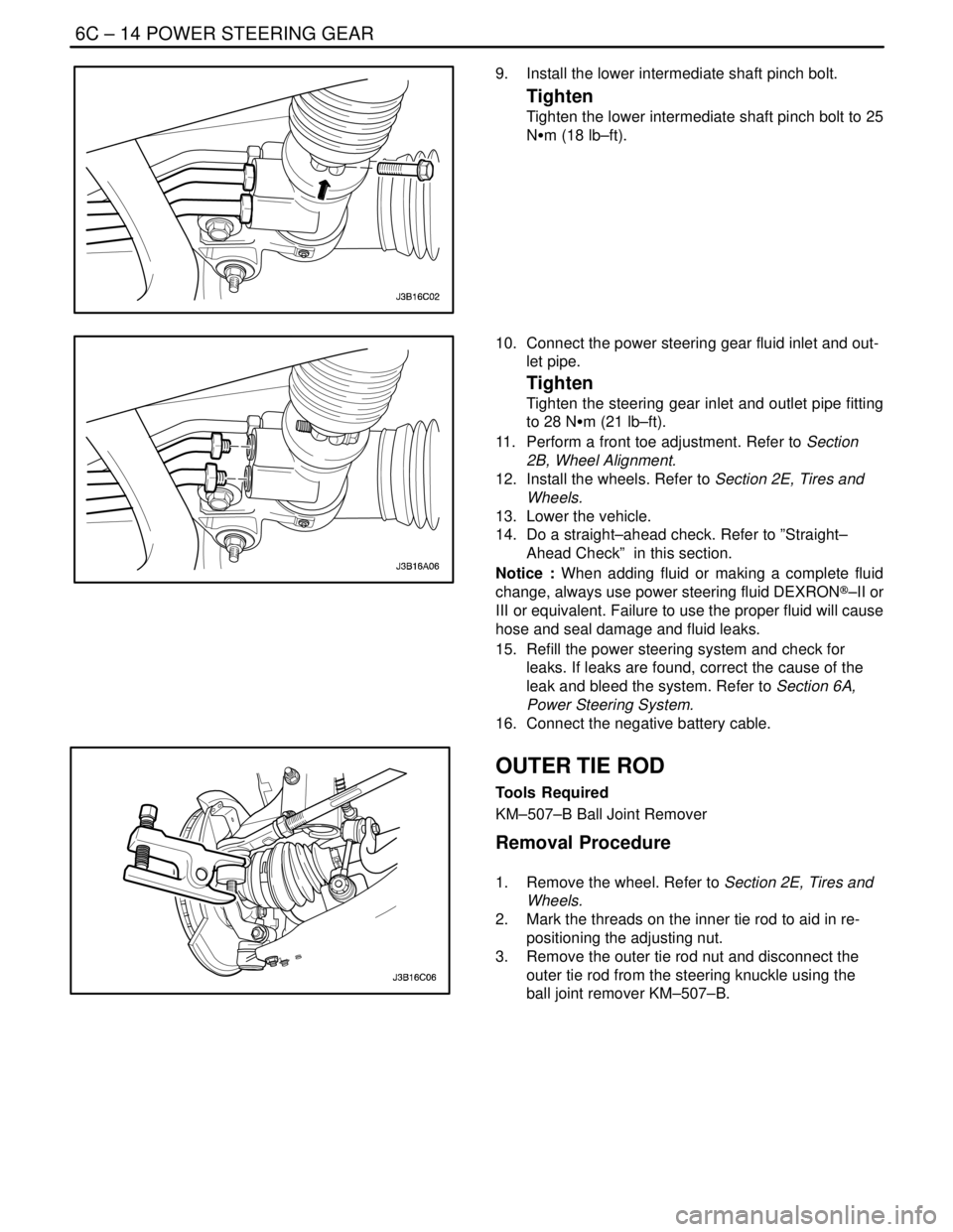
9. Install the lower intermediate shaft pinch bolt.
Tighten
Tighten the lower intermediate shaft pinch bolt to 25
NSm (18 lb–ft).
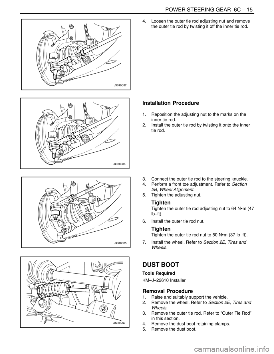
10. Connect the power steering gear fluid inlet and out-
let pipe.
Tighten
Tighten the steering gear inlet and outlet pipe fitting
to 28 NSm (21 lb–ft).
11. Perform a front toe adjustment. Refer to Section
2B, Wheel Alignment.
12. Install the wheels. Refer to Section 2E, Tires and
Wheels.
13. Lower the vehicle.
14. Do a straight–ahead check. Refer to ”Straight–
Ahead Check” in this section.
Notice : When adding fluid or making a complete fluid
change, always use power steering fluid DEXRON®–II or
III or equivalent. Failure to use the proper fluid will cause
hose and seal damage and fluid leaks.
15. Refill the power steering system and check for
leaks. If leaks are found, correct the cause of the
leak and bleed the system. Refer to Section 6A,
Power Steering System.
16. Connect the negative battery cable.
OUTER TIE ROD
Tools Required
KM–507–B Ball Joint Remover
Removal Procedure
1. Remove the wheel. Refer to Section 2E, Tires and
Wheels.
2. Mark the threads on the inner tie rod to aid in re-
positioning the adjusting nut.
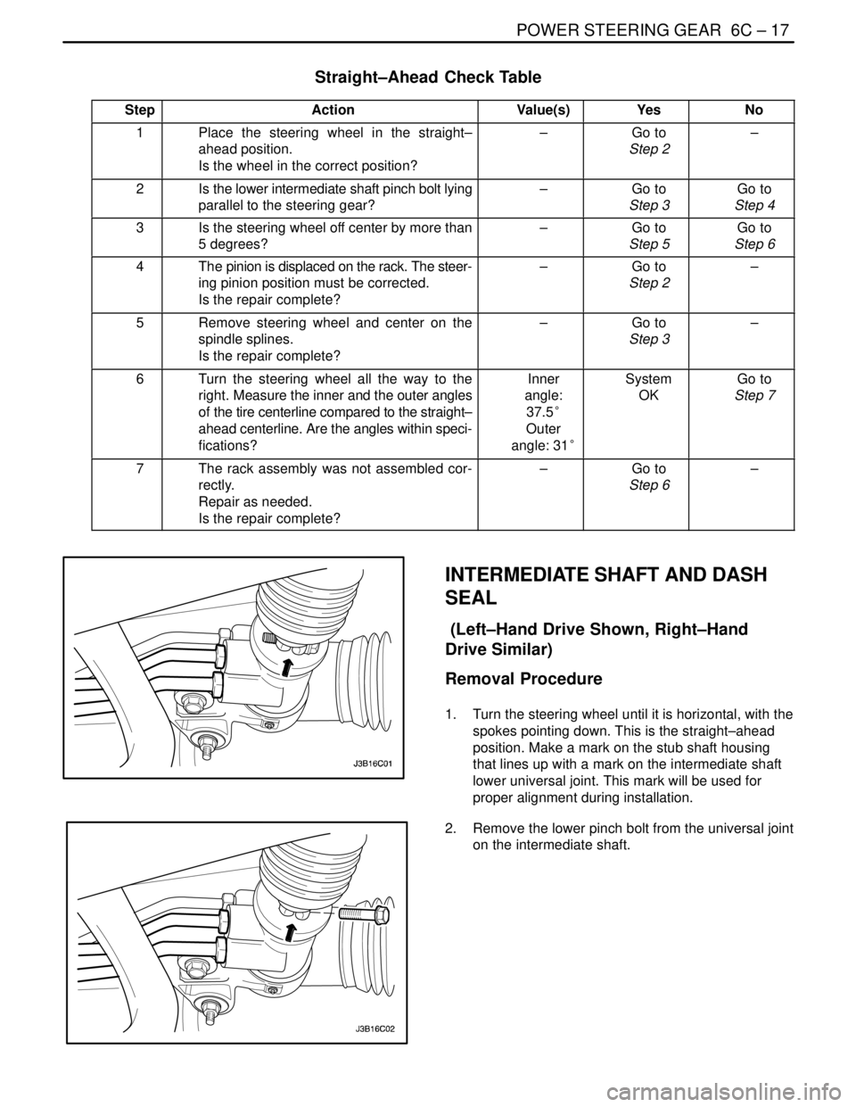
3. Remove the outer tie rod nut and disconnect the
outer tie rod from the steering knuckle using the
ball joint remover KM–507–B.
Page 1932 of 2643

POWER STEERING GEAR 6C – 15
DAEWOO V–121 BL4
4. Loosen the outer tie rod adjusting nut and remove
the outer tie rod by twisting it off the inner tie rod.
Installation Procedure
1. Reposition the adjusting nut to the marks on the
inner tie rod.
2. Install the outer tie rod by twisting it onto the inner
tie rod.
3. Connect the outer tie rod to the steering knuckle.
4. Perform a front toe adjustment. Refer to Section
2B, Wheel Alignment.
5. Tighten the adjusting nut.
Tighten
Tighten the outer tie rod adjusting nut to 64 NSm (47
lb–ft).
6. Install the outer tie rod nut.
Tighten
Tighten the outer tie rod nut to 50 NSm (37 lb–ft).
7. Install the wheel. Refer to Section 2E, Tires and
Wheels.
DUST BOOT
Tools Required
KM–J–22610 Installer
Removal Procedure
1. Raise and suitably support the vehicle.
2. Remove the wheel. Refer to Section 2E, Tires and
Wheels.
3. Remove the outer tie rod. Refer to ”Outer Tie Rod”
in this section.
4. Remove the dust boot retaining clamps.
5. Remove the dust boot.
Page 1934 of 2643

POWER STEERING GEAR 6C – 17
DAEWOO V–121 BL4
Straight–Ahead Check Table
StepActionValue(s)YesNo
1Place the steering wheel in the straight–
ahead position.
Is the wheel in the correct position?–Go to
Step 2–
2Is the lower intermediate shaft pinch bolt lying
parallel to the steering gear?–Go to
Step 3Go to
Step 4
3Is the steering wheel off center by more than
5 degrees?–Go to
Step 5Go to
Step 6
4The pinion is displaced on the rack. The steer-
ing pinion position must be corrected.
Is the repair complete?–Go to
Step 2–
5Remove steering wheel and center on the
spindle splines.
Is the repair complete?–Go to
Step 3–
6Turn the steering wheel all the way to the
right. Measure the inner and the outer angles
of the tire centerline compared to the straight–
ahead centerline. Are the angles within speci-
fications?Inner
angle:
37.5°
Outer
angle: 31°System
OKGo to
Step 7
7The rack assembly was not assembled cor-
rectly.
Repair as needed.
Is the repair complete?–Go to
Step 6–
INTERMEDIATE SHAFT AND DASH
SEAL
(Left–Hand Drive Shown, Right–Hand
Drive Similar)
Removal Procedure
1. Turn the steering wheel until it is horizontal, with the
spokes pointing down. This is the straight–ahead
position. Make a mark on the stub shaft housing
that lines up with a mark on the intermediate shaft
lower universal joint. This mark will be used for
proper alignment during installation.
2. Remove the lower pinch bolt from the universal joint
on the intermediate shaft.
Page 1942 of 2643
POWER STEERING GEAR 6C – 25
DAEWOO V–121 BL4
5. Install the cylinder end dust boot retaining clamps
with the installer KM–J–22610.
6. Install the tie rod end boot retaining clamps.
7. Reposition the adjusting nut to the marks on the
inner tie rod and install the outer tie rod by twisting
it onto the inner tie rod.
8. Perform a front toe adjustment. Refer to Section
2B, Wheel Alignment.
9. Tighten the adjusting nut.
Tighten
Tighten the outer tie rod adjusting nut to 64 NSm (47
lb–ft).
10. Install the rack bearing assembly into the rack and
pinion steering assembly. Refer to ”Rack Bearing”
in this section.
11. Install the valve and pinion assembly into the rack
and pinion steering assembly. Refer to ”Valve and
Pinion” in this section.
12. Install the rack and pinion steering assembly into
the vehicle. Refer to ”Rack and Pinion Assembly”
in this section.
Page 1957 of 2643

STEERING WHEEL AND COLUMN 6E – 3
DAEWOO V–121 BL4
High Lock Effort
ChecksAction
Check the lock cylinder for damage.Replace the lock cylinder.
Check the ignition switch for lack of free movement.Lubricate the ignition switch.
Check for extreme misalignment of the housing to the cov-
er.Realign the cover on the housing. Replace the cover as
needed.
Check for a bent ignition switch mounting bracket.Replace the ignition switch mounting bracket.
Key Cannot Be Removed in the LOCK Position
ChecksAction
Check to see that the ignition switch is set correctly.Reset the ignition switch.
Check the lock cylinder for damage.Replace the lock cylinder.
Check the fuse F17 from the I/P fuse block.Replace the fuse F17
Check for an open or short in the circuit between terminal
2 of key interlock solenoid and the I/P fuse block.Replace the fuse F17
Select the gear shift lever to ”P” position.
Check the resistance between the terminal 2 and 1 of the
”P” position switch.Replace the ”P” position switch.
Check for an open or short in the circuit between the
ground G202 and terminal 1 of the key interlock unit.Replace the open or short from the circuit.
Turn the ignition ON.
Select the gear shift lever to ”P” position.
Check the resistance between the terminal 1 and 2 of the
key interlock solenoid.Replace the key interlock solenoid.
Page 2197 of 2643

SUPPLEMENTAL INFLATABLE RESTRAINTS (SIR) 8B – 93
DAEWOO V–121 BL4
5. Remove the driver side knee bolster or instrument
panel lower cover.
6. Disconnect the driver airbag, horn and connectors
from the lower steering column.
7. Remove the screws and discard them.
8. Remove the clock spring from the steering shaft.
9. Installation should follow the removal procedure in
the reverse order. Refer to ”Clock Spring Align-
ment” in this section for alignment.
Tightening torque of the clock spring screw is 3 NSm
(27 lb–in).
CAUTION : If the clock spring is not properly
aligned, the steering wheel may not be able to ro-
tate completely during a turn. Restricted turning
ability can cause the vehicle to crash. Improper
alignment of the clock spring also may make the
SIR inoperative, preventing the airbag from de-
ploying during crash. Both of the out comes can
result in injury.
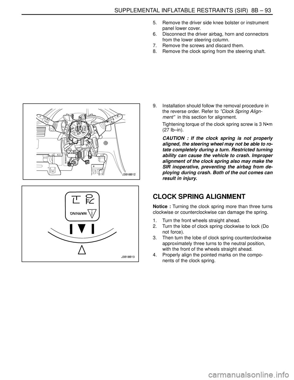
CLOCK SPRING ALIGNMENT
Notice : Turning the clock spring more than three turns
clockwise or counterclockwise can damage the spring.
1. Turn the front wheels straight ahead.
2. Turn the lobe of clock spring clockwise to lock (Do
not force).
3. Then turn the lobe of clock spring counterclockwise
approximately three turns to the neutral position,
with the front of the wheels straight ahead.
4. Properly align the pointed marks on the compo-
nents of the clock spring.
Page 2520 of 2643

1–12 GENERAL INFORMATIONNUBIRA/LACETTI
10. BODY REPAIR PROCEDURES
No.OperationProcedureRemarks
1InspectionInspect the damaged parts and the extent of damage and make
plans for the repair..
2PreparationPrepare the new parts, special repair tools and others..
3RemovalRemove the related parts for repair..
4Pull outRoughly pull out and straighten the damaged areas..
5Cut and pry offCut off the damaged areas and drills on the spot weld nuggets
and pry off the remaining spot weld flanges..
6Peel offPeel off the undercoat and sealer..
7MoldingMold damaged areas and even out the welding flanges and fill
any holes..
8Set the new partsGrind both sides of the welding section and set the new parts
and tack welds for temporary installation..
9InspectionInspect the dimensions for correct position and preinstall the ex-
terior parts and check the clearances and level differences..
10WeldingPerform a trial welding and the main welding..
11FinishFinish the welding areas and even out the flanges for a close fit..
12SealingApply the sealer to the matching and over lapped surface..
13UndercoatingApply the undercoat to the required areas..
14PaintingApply the paint..
15DeadnerApply the deadner to the designated areas..
16Anti–rust agentsCoating the anti–rust agents to the designated areas..
17InstallationInstall the related parts and rub in grease to the moving parts and
replenish the cooling liquid, oil, aircon gas and others..
18Check and adjustCheck all operations, wheel alignments, leaks, head lamp aim
and others with the specified check sheet..