Page 1266 of 2643
5–106WELECTRICAL WIRING DIAGRAMS
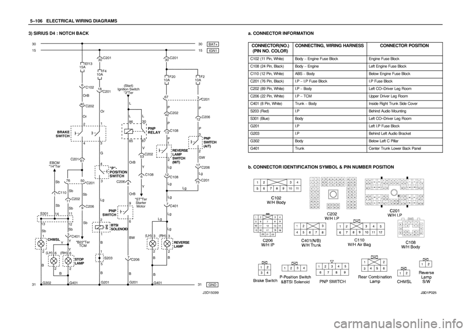
3) SIRIUS D4 : NOTCH BACKa. CONNECTOR INFORMATION
CONNECTOR(NO.)
(PIN NO. COLOR)
CONNECTING, WIRING HARNESSCONNECTOR POSITION
C102 (11 Pin, White)Body � Engine Fuse BlockEngine Fuse Block
C108 (24 Pin, Black)Body � EngineLeft Engine Fuse Block
C110 (12 Pin, White)ABS � BodyBelow Engine Fuse Block
C201 (76 Pin, Black)I.P � I.P Fuse BlockI.P Fuse Block
C202 (89 Pin, White)I.P � BodyLeft CO–Driver Leg Room
C206 (22 Pin, White)I.P � TCMUpper Driver Leg Room
C401 (8 Pin, White)Trunk � BodyInside Right Trunk Side Cover
S203 (Red)I.PBehind Audio Mounting
S301 (Blue)BodyLeft CO–Driver Leg Room
G201I.PLeft I.P Fuse Block
G203I.PBehind Left Audio Bracket
G302BodyBelow Left C Pillar
G401TrunkCenter Trunk Lower Back Panel
b. CONNECTOR IDENTIFICATION SYMBOL & PIN NUMBER POSITION
Page 1268 of 2643
 SIRIUS D4 : HATCH BACKa. CONNECTOR INFORMATION
CONNECTOR(NO.)
(PIN NO. COLOR)
CONNECTING, WIRING HARNESSCONNECTOR POSITION
C102 (11 Pin, White)Body � Engine Fuse")
5–108WELECTRICAL WIRING DIAGRAMS
4) SIRIUS D4 : HATCH BACKa. CONNECTOR INFORMATION
CONNECTOR(NO.)
(PIN NO. COLOR)
CONNECTING, WIRING HARNESSCONNECTOR POSITION
C102 (11 Pin, White)Body � Engine Fuse BlockEngine Fuse Block
C108 (24 Pin, Black)Body � EngineLeft Engine Fuse Block
C110 (12 Pin, White)ABS � BodyBelow Engine Fuse Block
C201 (76 Pin, Black)I.P � I.P Fuse BlockI.P Fuse Block
C202 (89 Pin, White)I.P � BodyLeft CO–Driver Leg Room
C206 (22 Pin, White)I.P � TCMUpper Driver Leg Room
C401 (6 Pin, White)Trunk – BodyInside Right Trunk Side Cover
C402 (6 Pin, White)Trunk LID – BodyInside Right Trunk Side Cover
C403 (6 Pin, White)T/Gate. EXT. � BodyInside Left C Pillar
C405 (8 Pin, White)T/Gate. EXT. � T/GateBeside Left Rear Wiper Motor
S203 (Red)I.PBehind Audio Mounting
S301 (Blue)BodyLeft CO–Driver Leg Room
G201I.PLeft I.P Fuse Block
G203I.PBehind Left Audio Bracket
G302BodyBelow Left C Pillar
G401TrunkCenter Trunk Lower Back Panel
b. CONNECTOR IDENTIFICATION SYMBOL & PIN NUMBER POSITION
Page 1270 of 2643
5–110WELECTRICAL WIRING DIAGRAMS
15.TRUNK/TAIL GATE OPEN SWITCH, TRUNK LATCH SWITCH, TRUNK
ROOM LAMP & HORN CIRCUIT
1) DUAL HORN
a. CONNECTOR INFORMATION
CONNECTOR(NO.)
(PIN NO. COLOR)
CONNECTING, WIRING HARNESSCONNECTOR POSITION
C101 (21 Pin, White)Body � Engine Fuse BlockEngine Fuse Block
C102 (11 Pin, White)Body � Engine Fuse BlockEngine Fuse Block
C104 (24 Pin, White)Front � Engine Fuse BlockEngine Fuse Block
C112 (2 Pin, Black)Front � HornCenter Cross Member Panel
C202 (89 Pin, White)I.P � BodyLeft CO–Driver Leg Room
C361 (33 Pin, Gray)Body � Front Light DoorUnder CO–Driver A Pillar
C402 (8 Pin, White)Trunk LID � BodyInside Right Trunk Side Cover
C404 (8 Pin, White)T/Gate. EXT. � BodyInside Left C Pillar
C406 (6 Pin, White)T/Gate. EXT. � T/GateBeside Left Rear Wiper Motor
G101FrontBehind Left Head Lamp
G302BodyBelow Left C Pillar
G402T/Gate. EXT.Inside Driver C Pillar
b. CONNECTOR IDENTIFICATION SYMBOL & PIN NUMBER POSITION
Page 1271 of 2643
ELECTRICAL WIRING DIAGRAMSW5–111
c. POSITION OF CONNECTORS AND GROUNDS
S W/H TRUNK
S W/H FRONT
S W/H DRIVE DOOR
S W/H INSTRUMENT PANEL
Page 1272 of 2643
5–112WELECTRICAL WIRING DIAGRAMS
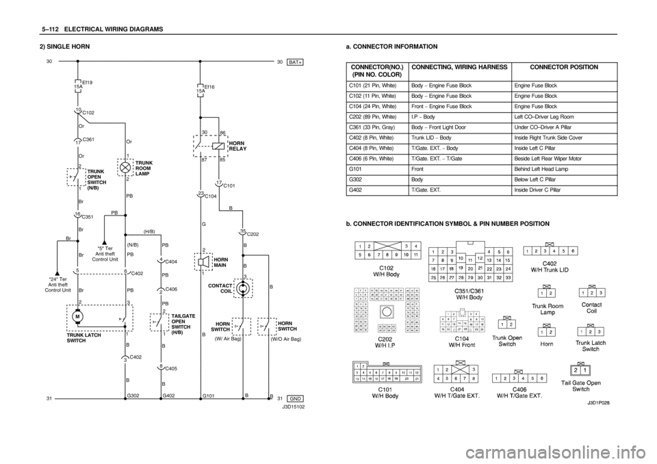
2) SINGLE HORNa. CONNECTOR INFORMATION
CONNECTOR(NO.)
(PIN NO. COLOR)
CONNECTING, WIRING HARNESSCONNECTOR POSITION
C101 (21 Pin, White)Body � Engine Fuse BlockEngine Fuse Block
C102 (11 Pin, White)Body � Engine Fuse BlockEngine Fuse Block
C104 (24 Pin, White)Front � Engine Fuse BlockEngine Fuse Block
C202 (89 Pin, White)I.P � BodyLeft CO–Driver Leg Room
C361 (33 Pin, Gray)Body � Front Light DoorUnder CO–Driver A Pillar
C402 (8 Pin, White)Trunk LID � BodyInside Right Trunk Side Cover
C404 (8 Pin, White)T/Gate. EXT. � BodyInside Left C Pillar
C406 (6 Pin, White)T/Gate. EXT. � T/GateBeside Left Rear Wiper Motor
G101FrontBehind Left Head Lamp
G302BodyBelow Left C Pillar
G402T/Gate. EXT.Inside Driver C Pillar
b. CONNECTOR IDENTIFICATION SYMBOL & PIN NUMBER POSITION
Page 1346 of 2643
 NOTCH BACK
a. CONNECTOR INFORMATION
CONNECTOR(NO.)
(PIN NO. COLOR)
CONNECTING, WIRING HARNESSCONNECTOR POSITION
C102 (11 Pin")
5–186WELECTRICAL WIRING DIAGRAMS
32. ANTI THEFT CONTROL SYSTEM CIRCUIT
1) NOTCH BACK
a. CONNECTOR INFORMATION
CONNECTOR(NO.)
(PIN NO. COLOR)
CONNECTING, WIRING HARNESSCONNECTOR POSITION
C102 (11 Pin, White)Body � Engine Fuse BlockEngine Fuse Block
C104 (24 Pin, White)Front � Engine Fuse BlockEngine Fuse Block
C105 (4 Pin, White)Body � Engine Fuse BlockEngine Fuse Block
C113 (16 Pin, Black)Body � FrontBehind ECM Bracket
C201 (76 Pin, Black)I.P � I.P Fuse BlockI.P Fuse Block
C202 (89 Pin, White)I.P � BodyLeft CO–Driver Leg Room
C351 (33 Pin, Gray)Body � Front Light DoorUnder CO–Driver A Pillar
C361 (33 Pin, Gray)Body � Front Right DoorUnder Driver A Pillar
C402 (8 Pin, White)Trunk LID � BodyInside Right Trunk Side Cover
S202 (Black)I.PBehind Cluster
S301 (Blue)BodyLeft CO–Driver Leg Room
S302 (Brown)BodyLeft CO–Driver Leg Room
G301BodyBelow Driver Cross Member Floor Panel
G302BodyBelow Left C Pillar
G303BodyBelow Left CO–Driver Leg Room
b. CONNECTOR IDENTIFICATION SYMBOL & PIN NUMBER POSITION
Page 2219 of 2643

EF260AB+EBCM, Oil Feeding Connector
EF330AB+Blower R")
BODY WIRING SYSTEM 9A – 13
DAEWOO V–121 BL4
FUSE CHART
Engine Room Fuse Block
FuseRating/SourceCircuit
EF130AB+Battery Main (F13~F16, F21~F24)
EF260AB+EBCM, Oil Feeding Connector
EF330AB+Blower Relay
EF430AB+Ignition Switch–2
EF530AB+Ignition Switch–1
EF620AB+Cooling Fan Low Relay
EF730AB+Defog Relay
EF830AB+Cooling Fan HI Relay
EF920AIGN 2Power Window Switch
EF1015AIGN 1Fuel Connector, ECM (MR–140), LEGR, EI Sys-
tem
EF1110AB+ECM, Main Relay (Sirius D4)
EF1225AB+Head Lamp Relay, ILLUM. Relay
EF1315AB+Brake Switch
EF1420AIGN 2Power Window Switch
EF1515ALightHead Lamp HI
EF1615AB+Horn Relay, Siren, Hood Contact Switch
EF1710AB+A/C Comp. Relay
EF1815AIGN 1Fuel Pump
EF1915AB+Cluster, Key Remind S/W, Folding Mirror Unit,
MAP Lamp, Room Lamp, Trunk Open Lamp,
Trunk Open S/W
EF2010ALightHead Lamp Low
EF2115AIGN 1/B+EVAP Canister Purge Solenoid, HO2S, Cooling
Fan Relay
EF2215AIGN 1/B+Injector, EGR, EEGR
EF2310AIlluminationLicense Plate Lamp, Chime Bell, Tail Lamp,
Head Lamp
EF2415AB+Fog LampRelay
EF2510AIGN 2Electric OSRV Mirror
EF2615AB+Central Door Lock Unit
EF2710ALightHead Lamp Low
EF2810AIlluminationILLUM. Circuit, Head Lamp, Tail Lamp
EF2910ASpareNot Used
EF3015ASpareNot Used
EF3125ASpareNot Used
Page 2335 of 2643
 Action
7Replace the speaker.
Is the repair complete?–System OK–
8Replace the cassette radio.
Is the repair complete?–System OK–
Re")
9F – 6IAUDIO SYSTEMS
DAEWOO V–121 BL4
StepNo Yes Value(s) Action
7Replace the speaker.
Is the repair complete?–System OK–
8Replace the cassette radio.
Is the repair complete?–System OK–
Rear Speakers Distorted or Inoperative, Rest of Audio System OK
StepActionValue(s)YesNo
11. Turn the ignition and the radio on.
2. Check for distorted or inoperative rear speak-
ers using the fader and the balance controls
with all the of the sources (AM, FM, tape, CD).
Are the rear speakers distorted?–Go to Step 2Go to Step 4
2Check the speakers, the rear deck, and the trunk
area for damage, rattles, or vibration.
Is there anything loose or in the way of the speaker
causing the distortion?–Go to Step 3Go to Step 4
3Make the necessary repairs to secure the compo-
nent causing the distortion.
Is the repair complete?–System OK–
41. Disconnect the rear speakers.
2. Using an ohmmeter, test the speaker wires for
a short to ground.
Does the ohmmeter show the specified value?�Go to Step 6Go to Step 5
5Repair the short circuit between the rear speaker
connector and the radio connector.
Is the repair complete?–System OK–
6Substitute a known good speaker for the speaker
causing the distortion.
Is the distortion eliminated?–Go to Step 7Go to Step 8
7Replace the speaker.
Is the repair complete?–System OK–
8Replace the audio system.
Is the repair complete?–System OK–
 DUAL HORN
a. CONNECTOR INFORMATION
CONNECTOR(NO.)
(PIN NO. COLOR)
CONNECTING, W")