2004 DAEWOO NUBIRA spark plug
[x] Cancel search: spark plugPage 163 of 2643
1.8L DOHC ENGINE MECHANICAL 1C2 – 43
DAEWOO V–121 BL4
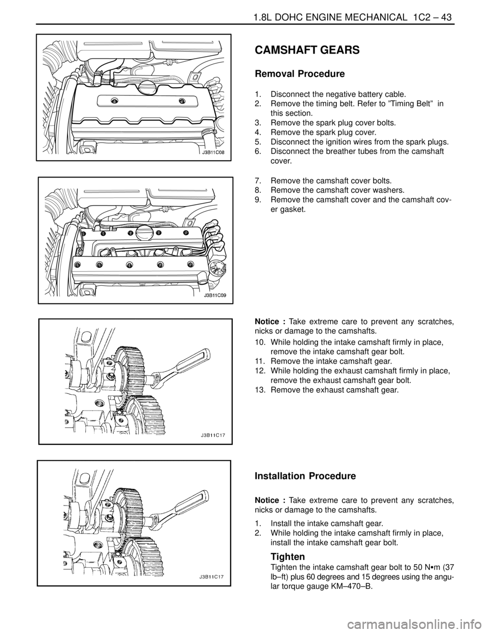
CAMSHAFT GEARS
Removal Procedure
1. Disconnect the negative battery cable.
2. Remove the timing belt. Refer to ”Timing Belt” in
this section.
3. Remove the spark plug cover bolts.
4. Remove the spark plug cover.
5. Disconnect the ignition wires from the spark plugs.
6. Disconnect the breather tubes from the camshaft
cover.
7. Remove the camshaft cover bolts.
8. Remove the camshaft cover washers.
9. Remove the camshaft cover and the camshaft cov-
er gasket.
Notice : Take extreme care to prevent any scratches,
nicks or damage to the camshafts.
10. While holding the intake camshaft firmly in place,
remove the intake camshaft gear bolt.
11. Remove the intake camshaft gear.
12. While holding the exhaust camshaft firmly in place,
remove the exhaust camshaft gear bolt.
13. Remove the exhaust camshaft gear.
Installation Procedure
Notice : Take extreme care to prevent any scratches,
nicks or damage to the camshafts.
1. Install the intake camshaft gear.
2. While holding the intake camshaft firmly in place,
install the intake camshaft gear bolt.
Tighten
Tighten the intake camshaft gear bolt to 50 NSm (37
lb–ft) plus 60 degrees and 15 degrees using the angu-
lar torque gauge KM–470–B.
Page 164 of 2643
1C2 – 44I1.8L DOHC ENGINE MECHANICAL
DAEWOO V–121 BL4
3. Install the exhaust camshaft gear.
4. While holding the exhaust camshaft firmly in place,
install the exhaust camshaft gear bolt.
Tighten
Tighten the exhaust camshaft gear bolt to 50 NSm (37
lb–ft) plus 60 degrees and 15 degrees using the angu-
lar torque gauge KM–470–B.
5. Apply a small amount of gasket sealant to the cor-
ners of the front camshaft caps and to the top of
the rear camshaft cover–to–cylinder head seal.
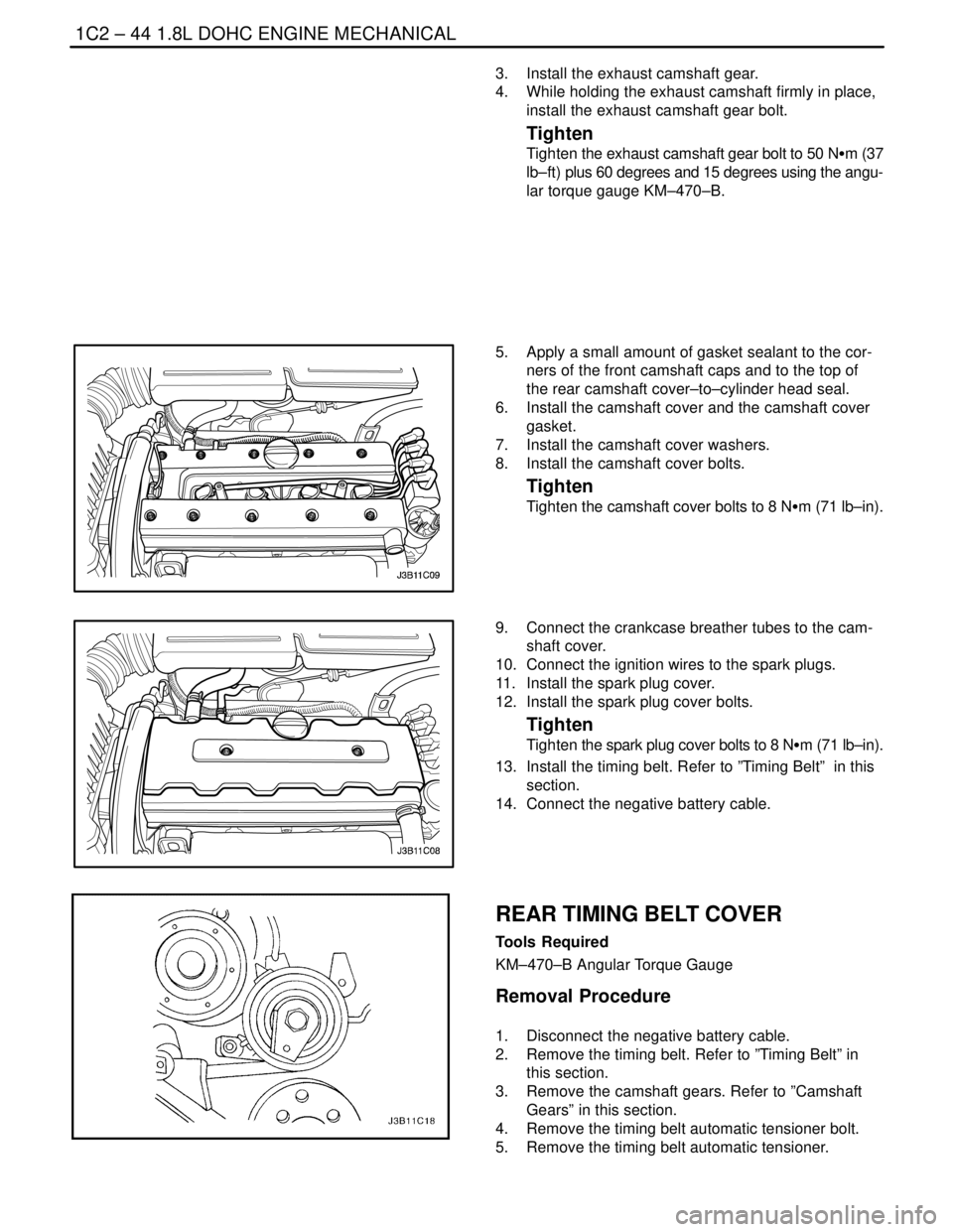
6. Install the camshaft cover and the camshaft cover
gasket.
7. Install the camshaft cover washers.
8. Install the camshaft cover bolts.
Tighten
Tighten the camshaft cover bolts to 8 NSm (71 lb–in).
9. Connect the crankcase breather tubes to the cam-
shaft cover.
10. Connect the ignition wires to the spark plugs.
11. Install the spark plug cover.
12. Install the spark plug cover bolts.
Tighten
Tighten the spark plug cover bolts to 8 NSm (71 lb–in).
13. Install the timing belt. Refer to ”Timing Belt” in this
section.
14. Connect the negative battery cable.
REAR TIMING BELT COVER
Tools Required
KM–470–B Angular Torque Gauge
Removal Procedure
1. Disconnect the negative battery cable.
2. Remove the timing belt. Refer to ”Timing Belt” in
this section.
3. Remove the camshaft gears. Refer to ”Camshaft
Gears” in this section.
4. Remove the timing belt automatic tensioner bolt.
5. Remove the timing belt automatic tensioner.
Page 177 of 2643
1.8L DOHC ENGINE MECHANICAL 1C2 – 57
DAEWOO V–121 BL4
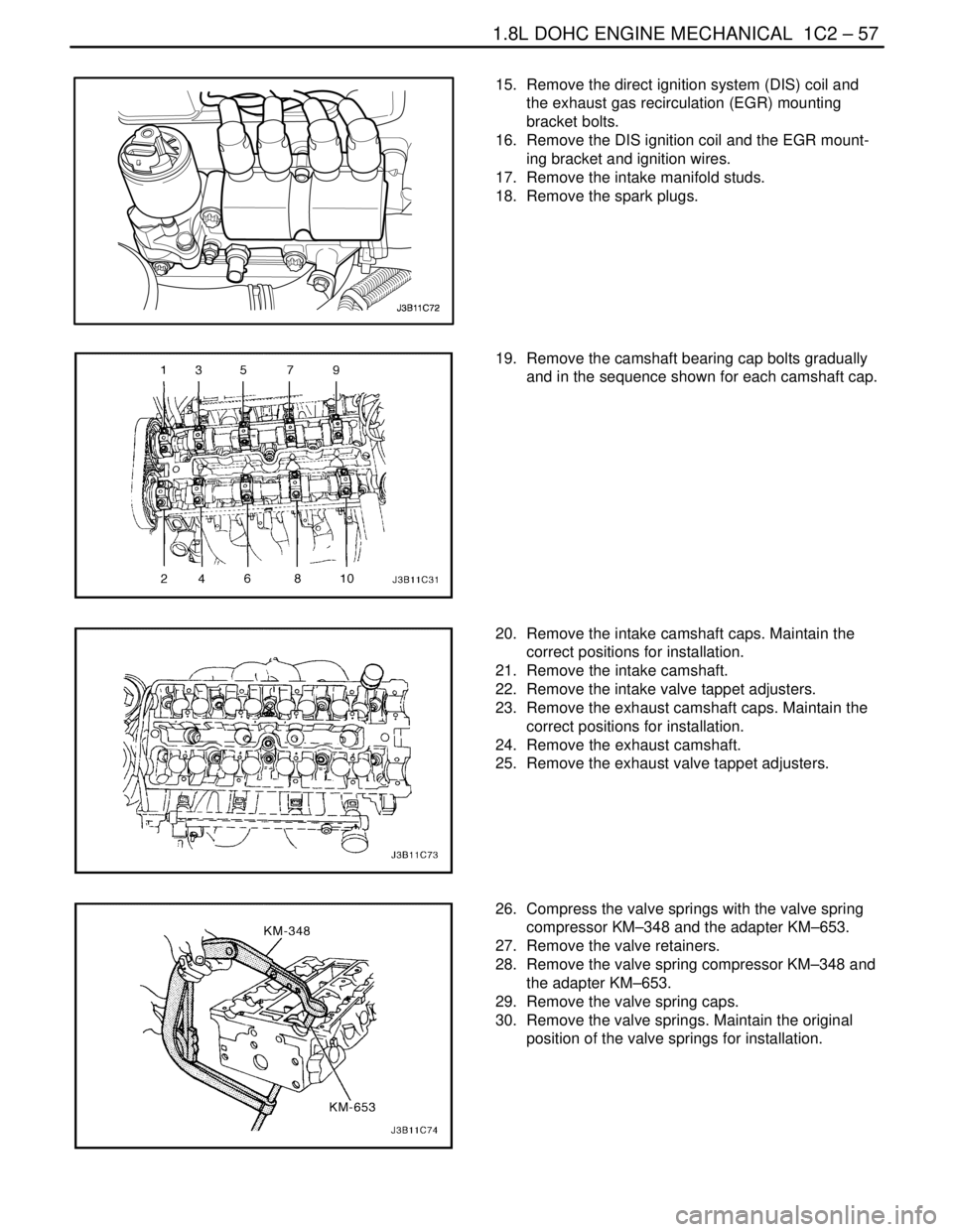
15. Remove the direct ignition system (DIS) coil and
the exhaust gas recirculation (EGR) mounting
bracket bolts.
16. Remove the DIS ignition coil and the EGR mount-
ing bracket and ignition wires.
17. Remove the intake manifold studs.
18. Remove the spark plugs.
19. Remove the camshaft bearing cap bolts gradually
and in the sequence shown for each camshaft cap.
20. Remove the intake camshaft caps. Maintain the
correct positions for installation.
21. Remove the intake camshaft.
22. Remove the intake valve tappet adjusters.
23. Remove the exhaust camshaft caps. Maintain the
correct positions for installation.
24. Remove the exhaust camshaft.
25. Remove the exhaust valve tappet adjusters.
26. Compress the valve springs with the valve spring
compressor KM–348 and the adapter KM–653.
27. Remove the valve retainers.
28. Remove the valve spring compressor KM–348 and
the adapter KM–653.
29. Remove the valve spring caps.
30. Remove the valve springs. Maintain the original
position of the valve springs for installation.
Page 182 of 2643
1C2 – 62I1.8L DOHC ENGINE MECHANICAL
DAEWOO V–121 BL4
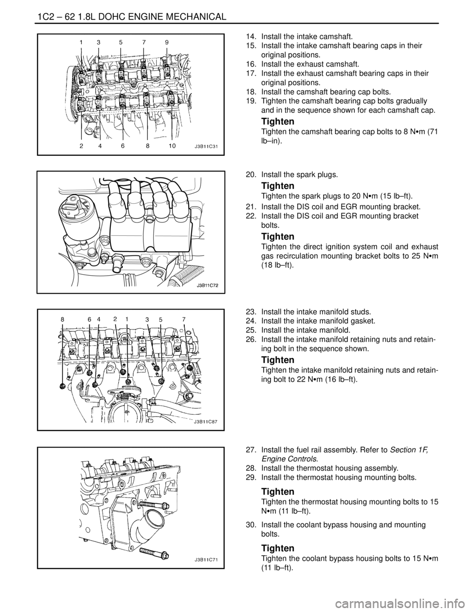
14. Install the intake camshaft.
15. Install the intake camshaft bearing caps in their
original positions.
16. Install the exhaust camshaft.
17. Install the exhaust camshaft bearing caps in their
original positions.
18. Install the camshaft bearing cap bolts.
19. Tighten the camshaft bearing cap bolts gradually
and in the sequence shown for each camshaft cap.
Tighten
Tighten the camshaft bearing cap bolts to 8 NSm (71
lb–in).
20. Install the spark plugs.
Tighten
Tighten the spark plugs to 20 NSm (15 lb–ft).
21. Install the DIS coil and EGR mounting bracket.
22. Install the DIS coil and EGR mounting bracket
bolts.
Tighten
Tighten the direct ignition system coil and exhaust
gas recirculation mounting bracket bolts to 25 NSm
(18 lb–ft).
23. Install the intake manifold studs.
24. Install the intake manifold gasket.
25. Install the intake manifold.
26. Install the intake manifold retaining nuts and retain-
ing bolt in the sequence shown.
Tighten
Tighten the intake manifold retaining nuts and retain-
ing bolt to 22 NSm (16 lb–ft).
27. Install the fuel rail assembly. Refer to Section 1F,
Engine Controls.
28. Install the thermostat housing assembly.
29. Install the thermostat housing mounting bolts.
Tighten
Tighten the thermostat housing mounting bolts to 15
NSm (11 lb–ft).
30. Install the coolant bypass housing and mounting
bolts.
Tighten
Tighten the coolant bypass housing bolts to 15 NSm
(11 lb–ft).
Page 184 of 2643
1C2 – 64I1.8L DOHC ENGINE MECHANICAL
DAEWOO V–121 BL4
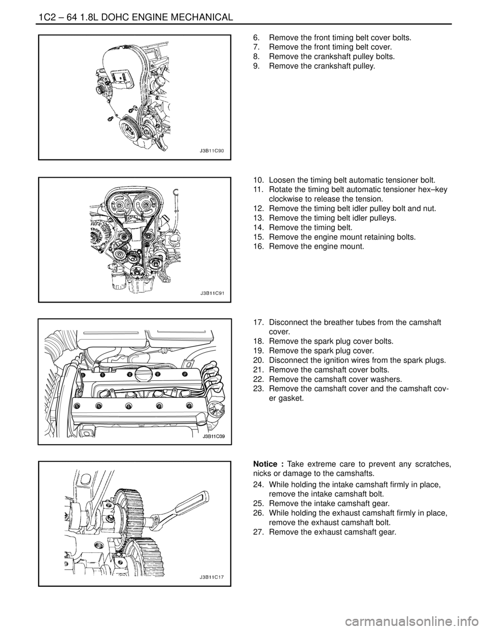
6. Remove the front timing belt cover bolts.
7. Remove the front timing belt cover.
8. Remove the crankshaft pulley bolts.
9. Remove the crankshaft pulley.
10. Loosen the timing belt automatic tensioner bolt.
11. Rotate the timing belt automatic tensioner hex–key
clockwise to release the tension.
12. Remove the timing belt idler pulley bolt and nut.
13. Remove the timing belt idler pulleys.
14. Remove the timing belt.
15. Remove the engine mount retaining bolts.
16. Remove the engine mount.
17. Disconnect the breather tubes from the camshaft
cover.
18. Remove the spark plug cover bolts.
19. Remove the spark plug cover.
20. Disconnect the ignition wires from the spark plugs.
21. Remove the camshaft cover bolts.
22. Remove the camshaft cover washers.
23. Remove the camshaft cover and the camshaft cov-
er gasket.
Notice : Take extreme care to prevent any scratches,
nicks or damage to the camshafts.
24. While holding the intake camshaft firmly in place,
remove the intake camshaft bolt.
25. Remove the intake camshaft gear.
26. While holding the exhaust camshaft firmly in place,
remove the exhaust camshaft bolt.
27. Remove the exhaust camshaft gear.
Page 191 of 2643
1.8L DOHC ENGINE MECHANICAL 1C2 – 71
DAEWOO V–121 BL4
Notice : Take extreme care to prevent any scratches,
nicks or damage to the camshafts.
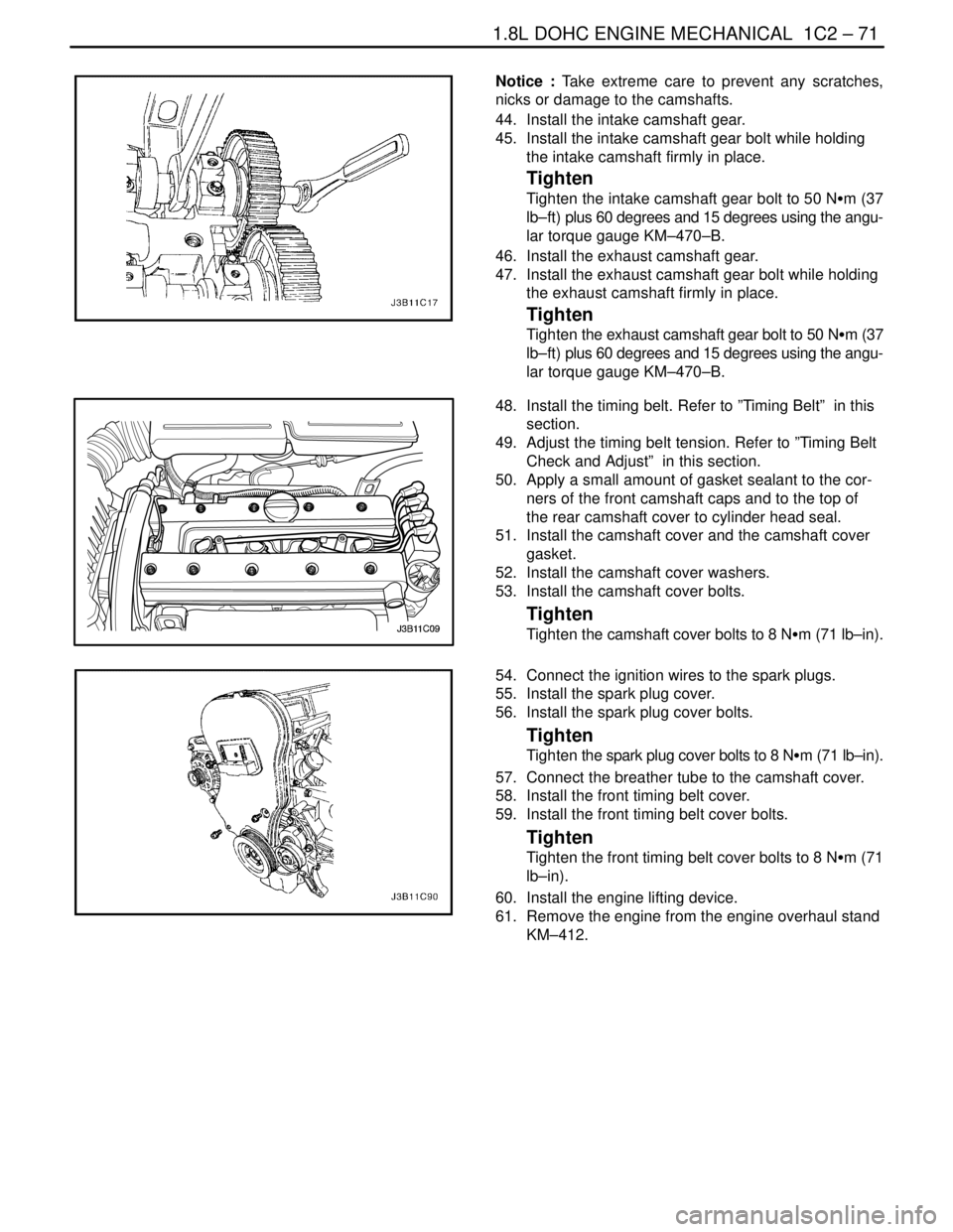
44. Install the intake camshaft gear.
45. Install the intake camshaft gear bolt while holding
the intake camshaft firmly in place.
Tighten
Tighten the intake camshaft gear bolt to 50 NSm (37
lb–ft) plus 60 degrees and 15 degrees using the angu-
lar torque gauge KM–470–B.
46. Install the exhaust camshaft gear.
47. Install the exhaust camshaft gear bolt while holding
the exhaust camshaft firmly in place.
Tighten
Tighten the exhaust camshaft gear bolt to 50 NSm (37
lb–ft) plus 60 degrees and 15 degrees using the angu-
lar torque gauge KM–470–B.
48. Install the timing belt. Refer to ”Timing Belt” in this
section.
49. Adjust the timing belt tension. Refer to ”Timing Belt
Check and Adjust” in this section.
50. Apply a small amount of gasket sealant to the cor-
ners of the front camshaft caps and to the top of
the rear camshaft cover to cylinder head seal.
51. Install the camshaft cover and the camshaft cover
gasket.
52. Install the camshaft cover washers.
53. Install the camshaft cover bolts.
Tighten
Tighten the camshaft cover bolts to 8 NSm (71 lb–in).
54. Connect the ignition wires to the spark plugs.
55. Install the spark plug cover.
56. Install the spark plug cover bolts.
Tighten
Tighten the spark plug cover bolts to 8 NSm (71 lb–in).
57. Connect the breather tube to the camshaft cover.
58. Install the front timing belt cover.
59. Install the front timing belt cover bolts.
Tighten
Tighten the front timing belt cover bolts to 8 NSm (71
lb–in).
60. Install the engine lifting device.
61. Remove the engine from the engine overhaul stand
KM–412.
Page 195 of 2643
1.8L DOHC ENGINE MECHANICAL 1C2 – 75
DAEWOO V–121 BL4
GENERAL DESCRIPTION
AND SYSTEM OPERATION
CYLINDER HEAD AND GASKET
The cylinder head is made of an aluminum alloy. The cylin-
der head uses cross–flow intake and exhaust ports. A
spark plug is located in the center of each combustion
chamber. The cylinder head houses the dual camshafts.
CRANKSHAFT
The crankshaft has eight integral weights which are cast
with it for balancing. Oil holes run through the center of the
crankshaft to supply oil to the connecting rods, the bear-
ings, the pistons, and the other components. The end
thrust load is taken by the thrust washers installed at the
center journal.
TIMING BELT
The timing belt coordinates the crankshaft and the dual
overhead camshafts and keeps them synchronized. The
timing belt also turns the coolant pump. The timing belt
and the pulleys are toothed so that there is no slippage be-
tween them. There are two idler pulleys. An automatic ten-
sioner pulley maintains the timing belt’s correct tension.
The timing belt is made of a tough reinforced rubber similar
to that used on the serpentine drive belt. The timing belt
requires no lubrication.
OIL PUMP
The oil pump draws engine oil from the oil pan and feeds
it under pressure to the various parts of the engine. An oil
strainer is mounted before the inlet of the oil pump to re-
move impurities which could clog or damage the oil pump
or other engine components. When the crankshaft ro-
tates, the oil pump driven gear rotates. This causes the
space between the gears to constantly open and narrow,
pulling oil in from the oil pan when the space opens and
pumping the oil out to the engine as it narrows.
At high engine speeds, the oil pump supplies a much high-
er amount of oil than required for lubrication of the engine.
The oil pressure regulator prevents too much oil from en-
tering the engine lubrication passages. During normal oil
supply, a coil spring and valve keep the bypass closed, di-
recting all of the oil pumped to the engine. When the
amount of oil being pumped increases, the pressure be-
comes high enough to overcome the force of the spring.This opens the valve of the oil pressure regulator, allowing
the excess oil to flow through the valve and drain back to
the oil pan.
OIL PAN
The engine oil pan is mounted to the bottom of the cylinder
block. The engine oil pan houses the crankcase and is
made of cast aluminum.
Engine oil is pumped from the oil pan by the oil pump. After
it passes through the oil filter, it is fed through two paths
to lubricate the cylinder block and cylinder head. In one
path, the oil is pumped through oil passages in the crank-
shaft to the connecting rods, then to the pistons and cylin-
ders. It then drains back to the oil pan. In the second path,
the oil is pumped through passages to the camshaft. The
oil passes through the internal passageways in the cam-
shafts to lubricate the valve assemblies before draining
back to the oil pan.
EXHAUST MANIFOLD
A single four–port, rear–takedown manifold is used with
this engine. The manifold is designed to direct escaping
exhaust gases out of the combustion chambers with a
minimum of back pressure. The oxygen sensor is
mounted to the exhaust manifold.
INTAKE MANIFOLD
The intake manifold has four independent long ports and
utilizes an inertial supercharging effect to improve engine
torque at low and moderate speeds.
CAMSHAFTS
This engine is a dual overhead camshaft (DOHC) type,
which means there are two camshafts. One camshaft op-
erates the intake valves, and the other camshaft operates
the exhaust valves. The camshafts sit in journals on the
top of the engine (in the cylinder head) and are held in
place by camshaft caps. The camshaft journals of the cyl-
inder head are drilled for oil passages. Engine oil travels
to the camshafts under pressure where it lubricates each
camshaft journal. The oil returns to the oil pan through
drain holes in the cylinder head. The camshaft lobes are
machined into the solid camshaft to precisely open and
close the intake and the exhaust valves the correct
amount at the correct time. The camshaft lobes are oiled
by splash action from pressurized oil escaping from the
camshaft journals.
Page 257 of 2643

ENGINE CONTROLS 1F – 11
DAEWOO V–121 BL4
FUEL SYSTEM SPECIFICATIONS
Gasoline
All engines are designed to use unleaded fuel only. Un-
leaded fuel must be used for proper emission control sys-
tem operation. Its use will also minimize spark plug fouling
and extend engine oil life. Using leaded fuel can damage
the emission warranty coverage. The fuel should meet
specification ASTM D4814 for the U.S. or CGSB 3.5 M93
for Canada. All engines are designed to use unleaded fuel
with a minimum U(R+M)/2e (pump) octane number of 87,
where R=research octane number, and M=motor octane
number.
Ethanol
You may use fuel containing ethanol (ethyl alcohol) orgrain alcohol providing that there is no more than 10 per-
cent ethyl alcohol by volume.
Methanol
Do not use fuels containing methanol. Methanol can cor-
rode metal parts and cause damage to plastic and rubber
parts in the fuel system.
Methyl Tertiary–Butyl Ether (MTBE)
You may use fuel containing Methyl Tertiary–Butyl Ether
(MTBE) providing there is no more than 15 percent MTBE
by volume.
TEMPERATURE VS RESISTANCE
°C°FECT SensorIAT Sensor
OHMS
Temperature vs Resistance Values (Approximate)
100212177187
90194241246
80176332327
70158467441
60140667603
50122973837
4511 31188991
4010414591180
359518021412
308622381700
257727962055
206835202500
155944503055
105056703760
54172804651
03294205800
–523123007273
–1014161809200
–155214509200
–20–42868015080
–30–225270025600
–40–4010070045300