Page 1610 of 2643
5A2 – 20IAISIN AUTOMATIC TRANSAXLE
DAEWOO V–121 BL4
1. Transaxle Housing
2. Oil Seal
3. Oil Reservoir Plate
4. Transaxle Oil Apply Pipe
5. Differential Gear Oil Apply Pipe
6. Transaxle Oil Apply Pipe Clamp
7. Spring
8. Check Valve Pipe Clamp
9. Apply Gasket
10. Brake Drun Gasket
11. Transaxle Wire
12. O–ring
13. Valve Body
14. Parking Lock Pawl
15. Parking Lock Pawl Shaft
16. Torsion Spring
17. Manual Valve lever Shaft
18. Manual Valve Lever
19. Parking Lock Rod
20. Parking Lock Pawl Bracket
21. Manual Detent Spring
22. Pin
23. Spacer24. Oil Seal
25. Transmission Range (TR) Switch
26. Lock Washer
27. Control Lever
28. Washer
29. Gasket
30. Oil Strainer
31. Oil Pan
32. Gasket
33. Magnet
34. Direct Clutch Accumulator Piston
35. O–ring
36. Spring
37. O–ring
38. Forward Clutch Accumulator Piston
39. O–ring
40. Spring
41. O–ring
42. Overdrive Brake Accumulator Piston
43. O–ring
44. O–ring
45. Spring
Page 1692 of 2643
5A2 – 102IAISIN AUTOMATIC TRANSAXLE
DAEWOO V–121 BL4
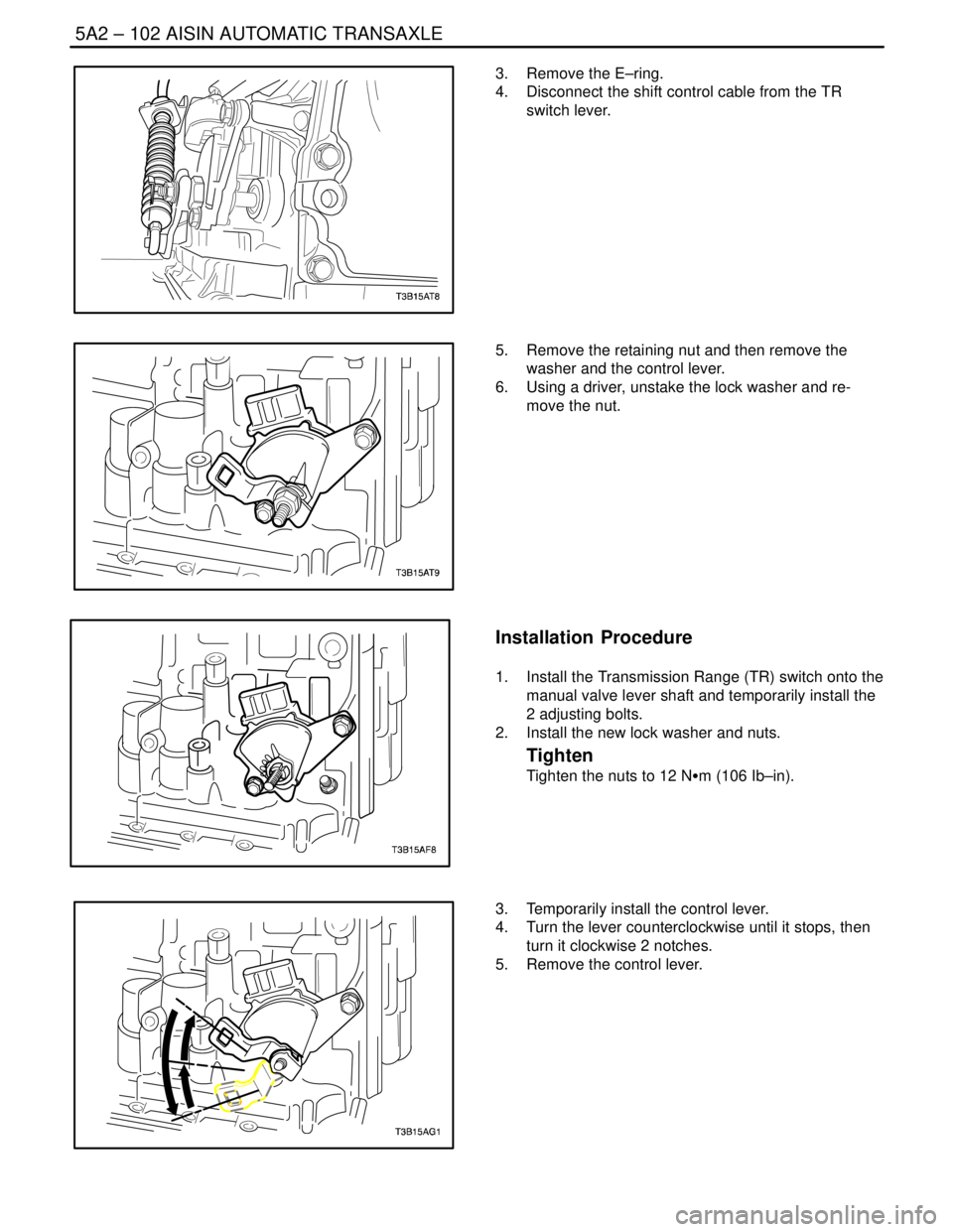
3. Remove the E–ring.
4. Disconnect the shift control cable from the TR
switch lever.
5. Remove the retaining nut and then remove the
washer and the control lever.
6. Using a driver, unstake the lock washer and re-
move the nut.
Installation Procedure
1. Install the Transmission Range (TR) switch onto the
manual valve lever shaft and temporarily install the
2 adjusting bolts.
2. Install the new lock washer and nuts.
Tighten
Tighten the nuts to 12 NSm (106 Ib–in).
3. Temporarily install the control lever.
4. Turn the lever counterclockwise until it stops, then
turn it clockwise 2 notches.
5. Remove the control lever.
Page 1887 of 2643
FIVE–SPEED MANUAL TRANSAXLE 5B – 63
DAEWOO V–121 BL4
GENERAL DESCRIPTION
AND SYSTEM OPERATION
FIVE–SPEED MANUAL TRANSAXLE
This five–speed transaxle assembly is a transmission of
constant–mesh design.
Combined in the assembly are:
S All forward gears.
S The reverse gear.
S The differential output.
The basic components of the five–speed transaxle as-
sembly units are the:
S Transaxle case.
S Input shaft.
S Input shaft gears.S Output shaft.
S Output shaft gears.
S Ring gear and differential assembly.
Forward Gear
Shifting to a forward gear is accomplished through a com-
bination of synchronizers with blocker rings controlled by
sliding shift forks.
Reverse Gear
Reverse gear is not synchronized and uses a sliding idler
gear arrangement.
Differential Assembly
The differential is a conventional arrangement of gears
that is supported by tapered roller bearings. The final out-
put gear turns the ring gear and differential assembly
which turns the drive axle shafts.
Page:
< prev 1-8 9-16 17-24