Page 1298 of 2643
5–138WELECTRICAL WIRING DIAGRAMS
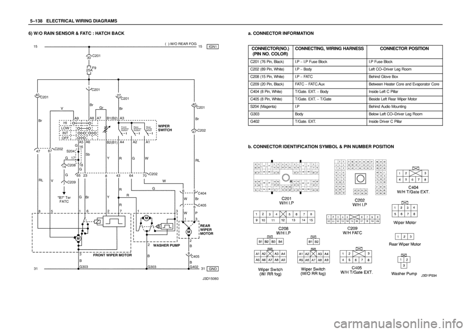
6) W/O RAIN SENSOR & FATC : HATCH BACKa. CONNECTOR INFORMATION
CONNECTOR(NO.)
(PIN NO. COLOR)
CONNECTING, WIRING HARNESSCONNECTOR POSITION
C201 (76 Pin, Black)I.P � I.P Fuse BlockI.P Fuse Block
C202 (89 Pin, White)I.P � BodyLeft CO–Driver Leg Room
C208 (15 Pin, White)I.P � FAT CBehind Glove Box
C209 (20 Pin, Black)FAT C � FAT C . A u xBetween Heater Core and Evaporator Core
C404 (8 Pin, White)T/Gate. EXT. � BodyInside Left C Pillar
C405 (8 Pin, White)T/Gate. EXT. � T/GateBeside Left Rear Wiper Motor
S204 (Magenta)I.PBehind Audio Mounting
G303BodyBelow Left CO–Driver Leg Room
G402T/Gate. EXT.Inside Driver C Pillar
b. CONNECTOR IDENTIFICATION SYMBOL & PIN NUMBER POSITION
Page 1300 of 2643
5–140WELECTRICAL WIRING DIAGRAMS
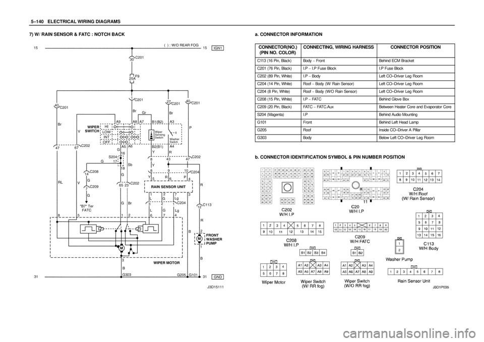
7) W/ RAIN SENSOR & FATC : NOTCH BACKa. CONNECTOR INFORMATION
CONNECTOR(NO.)
(PIN NO. COLOR)
CONNECTING, WIRING HARNESSCONNECTOR POSITION
C113 (16 Pin, Black)Body � FrontBehind ECM Bracket
C201 (76 Pin, Black)I.P � I.P Fuse BlockI.P Fuse Block
C202 (89 Pin, White)I.P � BodyLeft CO–Driver Leg Room
C204 (14 Pin, White)Roof � Body (W/ Rain Sensor)Left CO–Driver Leg Room
C204 (8 Pin, White)Roof � Body (W/O Rain Sensor)Left CO–Driver Leg Room
C208 (15 Pin, White)I.P � FAT CBehind Glove Box
C209 (20 Pin, Black)FAT C � FAT C . A u xBetween Heater Core and Evaporator Core
S204 (Magenta)I.PBehind Audio Mounting
G101FrontBehind Left Head Lamp
G205RoofInside CO–Driver A Pillar
G303BodyBelow Left CO–Driver Leg Room
b. CONNECTOR IDENTIFICATION SYMBOL & PIN NUMBER POSITION
Page 1302 of 2643
5–142WELECTRICAL WIRING DIAGRAMS
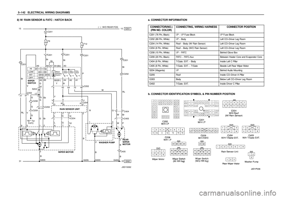
8) W/ RAIN SENSOR & FATC : HATCH BACKa. CONNECTOR INFORMATION
CONNECTOR(NO.)
(PIN NO. COLOR)
CONNECTING, WIRING HARNESSCONNECTOR POSITION
C201 (76 Pin, Black)I.P � I.P Fuse BlockI.P Fuse Block
C202 (89 Pin, White)I.P � BodyLeft CO–Driver Leg Room
C204 (14 Pin, White)Roof � Body (W/ Rain Sensor)Left CO–Driver Leg Room
C204 (8 Pin, White)Roof � Body (W/O Rain Sensor)Left CO–Driver Leg Room
C208 (15 Pin, White)I.P � FAT CBehind Glove Box
C209 (20 Pin, Black)FAT C � FAT C . A u xBetween Heater Core and Evaporator Core
C404 (8 Pin, White)T/Gate. EXT. � BodyInside Left C Pillar
C405 (8 Pin, White)T/Gate. EXT. � T/GateBeside Left Rear Wiper Motor
S204 (Magenta)I.PBehind Audio Mounting
G205RoofInside CO–Driver A Pillar
G303BodyBelow Left CO–Driver Leg Room
G402T/Gate. EXT.Inside Driver C Pillar
b. CONNECTOR IDENTIFICATION SYMBOL & PIN NUMBER POSITION
Page 1304 of 2643

(PIN NO. COLOR)
CONNECTING, WIRING HARNESSCONNECTOR POSITION
C")
5–144WELECTRICAL WIRING DIAGRAMS
20. REAR WINDOW DEFROSTER & OSRV MIRROR HEATING SYSTEM
CIRCUITa. CONNECTOR INFORMATION
CONNECTOR(NO.)
(PIN NO. COLOR)
CONNECTING, WIRING HARNESSCONNECTOR POSITION
C101 (21 Pin, White)Body � Engine Fuse BlockEngine Fuse Block
C102 (11 Pin, White)Body � Engine Fuse BlockEngine Fuse Block
C201 (76 Pin, Black)I.P � I.P Fuse BlockI.P Fuse Block
C202 (89 Pin, White)I.P � BodyLeft CO–Driver Leg Room
C208 (15 Pin, White)I.P � FAT CBehind Glove Box
C209 (20 Pin, Black)FAT C � FAT C . A u xBetween Heater Core and Evaporator Core
C351 (33 Pin, Gray)Body � Front Light DoorUnder CO–Driver A Pillar
C361 (33 Pin, Gray)Body � Front Right DoorUnder Driver A Pillar
C404 (8 Pin, White)T/Gate. EXT. � BodyInside Left C Pillar
C405 (8 Pin, White)T/Gate. EXT. � T/GateBeside Left Rear Wiper Motor
C406 (6 Pin, White)T/Gate. EXT. � T/GateBeside Left Rear Wiper Motor
S302 (Brown)BodyLeft CO–Driver Leg Room
G301BodyBelow Driver Cross Member Floor Panel
G303BodyBelow Left CO–Driver Leg Room
G402T/Gate. EXT.Inside Driver C Pillar
b. CONNECTOR IDENTIFICATION SYMBOL & PIN NUMBER POSITION
Page 2112 of 2643

DAEWOO V–121 BL4
SIR DIAGNOSTIC SYSTEM CHECK
Notice : If the vehicle interior has been exposed to exten-
sive water intrusion such as water leaks, d")
8B – 8ISUPPLEMENTAL INFLATABLE RESTRAINTS (SIR)
DAEWOO V–121 BL4
SIR DIAGNOSTIC SYSTEM CHECK
Notice : If the vehicle interior has been exposed to exten-
sive water intrusion such as water leaks, driving through
high water, flooding, or other causes, the sensing and
diagnostic module(SDM) and SDM connector may need
to be replaced. With ignition OFF, inspect the area around
the SDM, including the carpet. If any significant soaking or
evidence of previous soaking is detected, the water must
be removed, water damage repaired, and the SDM and
the SDM connector must be replaced. Before attempting
any of these repairs, the supplemental inflatable re-
straints(SIR) must be disabled. Refer to ”Disabling the
SIR” and ”Sensing and Diagnostic Module(SDM)” in this
section for instructions on how to disable the SIR and re-
place the SDM.
The SIR Diagnostic System Check must always be the
starting point for any SIR diagnosis. The Diagnostic Sys-
tem Check reveals diagnostic trouble codes(DTCs)
through the use of scan tool. The diagnostic procedures
used in this section are designed to find any repair SIR
conditions. To get the best results, it is important to use the
diagnostic charts and follow the sequence listed below.
1. Perform the SIR Diagnostic System Check, which
reveal diagnostic trouble codes(DTCs) through theuse of scan tool.. It also checks for proper airbag
indicator operation.
2. Refer to the proper diagnostic chart as directed by
SIR Diagnostic System Check. Bypassing these
procedures may result in extended diagnostic time,
incorrect diagnosis, and incorrect parts replace-
ment.
3. Repeat the SIR Diagnostic System Check after any
repair or diagnostic procedures have been per-
formed to ensure that the repair has been made
correctly and that no other malfunction exists.
Circiut Description
When the ignition switch is first turned to ON, ignition volt-
age is supplied from airbag fuse to find the SDM at input
terminal A1. The SDM responds by flashing the airbag in-
dicator seven times and then turning it off while the SDM
performs tests on the SIR.
Diagnostic Aids
The order in which DTCs are diagnosed is very important.
Failure to diagnose the DTCs in the order specified may
result in extended diagnostic time, incorrect diagnosis,
and incorrect parts replacement.
SIR Diagnostic System Check
CAUTION : The sensing and the diagnosis module
(SDM) can maintain surfficient voltage to deploy the
airbags and pretensioners for 1 minute after the igni-
tion is OFF and the fuse has been removed. If the air-
bags and pretensioners are not disconnected, do not
begin service until one minute has been passed after
disconnecting power to the SDM. Otherwise, injury
could result.
CAUTION : During service procedure, be very careful
when handling the SDM. Never strike or jar the SDM.Never power the supplemental inflatable re-
straints(SIR) when the SDM is not rigidly attached to
the vehicle. All SDM mounting bolts must be carefully
tightened , and the arrow on the SDM must be point
toward the front of the vehicle to ensure proper op-
eration of the SIR. The SDM could be activated if it is
powered when it is not rigidly attached to the vehicle,
resulting in unexpected deployment and possible in-
jury.
Step
ActionValue(s)YesNo
11. Turn the ignition switch ON.
2. Observe the airbag indicator as the ignition is
being turned ON. Does the indicator flash
seven times?–System OKGo to Step 2
21. Turn the ignition to LOCK and remove the key.
2. Connect the scan tool to the data link connec-
tor(DLC). Follow the directions given in the
scan tool manual.
3. Are any DTCs displayed on the scan tool?–Go to the
DTC check
procedureGo to Step 3
3Check the fuse F1 in the interior fuse box.
Is the fuse F1 blown?–Go to Step 4Go to Step 5
4Replace the fuse F1.–––
51. Disconnect the connector C207.
2. Check the wiring shortage between the fuse F1
and the terminal 1 of the connector C207.
3. Is the wiring shorted? Then, repair the wiring.––Go to Step 6
Page 2148 of 2643

DAEWOO V–121 BL4
J3B18B06
YEL
10AI/P
Fuse
Box
1 PNKC201
C207
SDM
BLK/
WHTF1
Hot in Run and Start
65 17
G202
DIAGNOSTIC TROUBLE CODE (DTC) 23
BATTER")
8B – 44ISUPPLEMENTAL INFLATABLE RESTRAINTS (SIR)
DAEWOO V–121 BL4
J3B18B06
YEL
10AI/P
Fuse
Box
1 PNKC201
C207
SDM
BLK/
WHTF1
Hot in Run and Start
65 17
G202
DIAGNOSTIC TROUBLE CODE (DTC) 23
BATTERY VOLTAGE HIGH
Circuit Description
When the ignition switch is turned to ON, the sensing and
diagnostic module(SDM) will perform turn–on test to diag-
nose critical malfunctions within SDM itself.
Upon passing these test ignition and deployment loop volt-
ages are measured to ensure that they are within their nor-
mal voltage ranges. The SDM monitors the voltages at the
driver low and the passenger low to detect shorts to
ground or voltage in the deploy loops.The SDM checks the wiring connection to the passenger
airbag module by letting the infinitesimal current flow
through the internal circuit and verify the resistance. But
if the voltage is out of range, SDM is unable to check the
airbag system properly.
DTC 23 Will Set When
S The voltage supplied from the battery is over 16.5
volts.
Page 2150 of 2643

DAEWOO V–121 BL4
J3B18B06
YEL
10AI/P
Fuse
Box
1 PNKC201
C207
SDM
BLK/
WHTF1
Hot in Run and Start
65 17
G202
DIAGNOSTIC TROUBLE CODE (DTC) 24
BATTER")
8B – 46ISUPPLEMENTAL INFLATABLE RESTRAINTS (SIR)
DAEWOO V–121 BL4
J3B18B06
YEL
10AI/P
Fuse
Box
1 PNKC201
C207
SDM
BLK/
WHTF1
Hot in Run and Start
65 17
G202
DIAGNOSTIC TROUBLE CODE (DTC) 24
BATTERY VOLTAGE HIGE
Circuit Description
When the ignition switch is turned to ON, the sensing and
diagnostic module(SDM) will perform turn–on test to diag-
nose critical malfunctions within SDM itself.
Upon passing these test ignition and deployment loop volt-
ages are measured to ensure that they are within their nor-
mal voltage ranges. The SDM monitors the voltages at the
driver low and the passenger low to detect shorts to
ground or voltage in the deploy loops.The SDM checks the wiring connection to the passenger
airbag module by letting the infinitesimal current flow
through the internal circuit and verify the resistance. But
if the voltage is out of range, SDM is unable to check the
airbag system properly.
DTC 24 Will Set When
S The voltage supplied from the battery is lower than
10.6 volts.
Page 2198 of 2643

DAEWOO V–121 BL4
PASSENGER AIRBAG MODULE
Removal and Installation Procedure
CAUTION : The sensing and diagnostic mod-
ule(SDM) can maintain suffici")
8B – 94ISUPPLEMENTAL INFLATABLE RESTRAINTS (SIR)
DAEWOO V–121 BL4
PASSENGER AIRBAG MODULE
Removal and Installation Procedure
CAUTION : The sensing and diagnostic mod-
ule(SDM) can maintain sufficient voltage to
deploy the airbags and pretensioners for 1minute
after the ignition is OFF and the fuse has been re-
moved. If the airbags and pretensioners are not
disconnected, do not begin service until one
minute has passed after disconnecting power to
SDM. If the airbags are disconnected, service can
be excuted immediately without waiting for one–
minute time period to expire. Failure to tempo-
rarily disable the SIR during service can result in
unexpected deployment, personal injury and un-
necessary SIR repairs.
1. Disconnect the negative battery cable.
2. Remove the glove box. Refer to 9E, Instrumenta-
tion/Driver Information.
3. Disconnect the passenger airbag yellow electrical
connector. Remove the Instrument panel.
4. Remove the passenger airbag module by removing
the mounting bolts from the airbag bracket.
5. Installation should follow the removal procedure in
the reverse order.
Tightening torque of the passenger airbag module
mounting bolt is 11 NSm (97 lb–in).