Page 1538 of 2643

ZF 4 HP 16 AUTOMATIC TRANSAXLE 5A1 – 189
DAEWOO V–121 BL4
S No input speed error DTCs P0715, P0716, or
P0717.
S Output speed is greater than 256 rpm.
S Input speed is greater than 400 rpm.
S 4–2 gear shift is active.
S Immediately after the above condition occurs.
Action Taken When The DTC Sets
S The Malfunction Indicator Lamp(MIL) will illuminate.
S The TCM will record operating conditions at the
time the diagnostic fails. This information will be
stored in the Failure Records buffer.
S Adopt Emergency/ Substitute mode and constant
4th gear.S Open lock–up clutch.
Conditions for Clearing the MIL/DTC
S The MIL will turn OFF when the malfunction has
not occurred after three–ignition cycle.
S A history DTC will clear after 40 consecutive warm
up cycles without a fault.
S Using a scan tool can clear history DTCs.
Diagnostic Aids
S When DTC P1886 sets, the possible cause of fault
could be TCM.
DTC P1886 – 4–2 Shift Malfunction
StepActionValue(s)YesNo
1Perform an On–Board Diagnostic (EOBD) System
Check.
Is the check completed?–Go to Step 2Go to ”On–
Board Diagnos-
tic System
Check”
21. Install the scan tool.
2. Turn the ignition ON, with the engine OFF.
Then, start engine and allow it to warm up at
idle.
3. Observe ”idle rpm, TPS” on the scan tool.
Was a problem found?–Go to ”Engine
Diagnostic In-
formation”Go to Step 3
3Inspect ”ECM”. Refer to Section 1F, System Diagno-
sis, EOBD System Check.
Was a problem found?–Go to ”Engine
Diagnostic In-
formation”Go to Step 4
41. Turn the ignition OFF.
2. Disconnect the TCM wiring connector.
3. Measure the voltage between terminal B3 and
B13 of the transaxle wiring connector.
4. Turn the ignition ON.
5. Measure the voltage between terminal C15 and
B13 of the transaxle wiring connector.
6. Measure the voltage between terminal C16 and
B13 of the transaxle wiring connector.
Is the voltage within the values shown?11–14VGo to Step 5Go to ”System
Voltage Low or
High”
5Replace the TCM.
Is the action complete?–Go to Step 6–
61. After the repair, use a scan tool ”clear info”
function and road test the vehicle.
2. Review the ”DTC info”.
Has the last test failed or is the current DTC dis-
played?–Replace the
transaxle as-
semblyRepair verified
exit DTC chart
Page 1563 of 2643
5A1 – 214IZF 4 HP 16 AUTOMATIC TRANSAXLE
DAEWOO V–121 BL4
CLUTCH B/E
Tools Required
DW260–140 Clutch B Stop Ring Remover/Installer
DW260–150 Clutch B Stop Ring Remover/Installer
Disassembly and Assembly Procedure
1. Remove the rear cover. Refer to ”Rear Cover Re-
moval” in this section.
2. Remove the two sealing rings(clutch B/E).
3. Take out input shaft with clutch B/E.
4. Remove needle bearing and thrust washer.
5. Remove shim.
6. Take out the retaining snap ring.
Page 1565 of 2643
5A1 – 216IZF 4 HP 16 AUTOMATIC TRANSAXLE
DAEWOO V–121 BL4
11. Take out the snap ring.
12. Remove disc set E.
13. Press down cup spring(clutch E) with cup spring
press fixture.
14. Remove the split stop ring.
15. Remove the oil dam and cup spring.
16. Pull the o–ring off the oil dam.
Page 1566 of 2643
ZF 4 HP 16 AUTOMATIC TRANSAXLE 5A1 – 217
DAEWOO V–121 BL4
17. Press down cup spring(clutch B)with cup spring
press fixture.
18. Remove the split stop ring.
19. Remove the cup spring.
20. Installation should follow the removal procedure in
the reverse order.
Adjustment Notice
Before assembling clutch B/E, setting discs(clutch B/E)
have to measured by below measurement procedure.
CLUTCH B/E MEASUREMENT
PROCEDURE
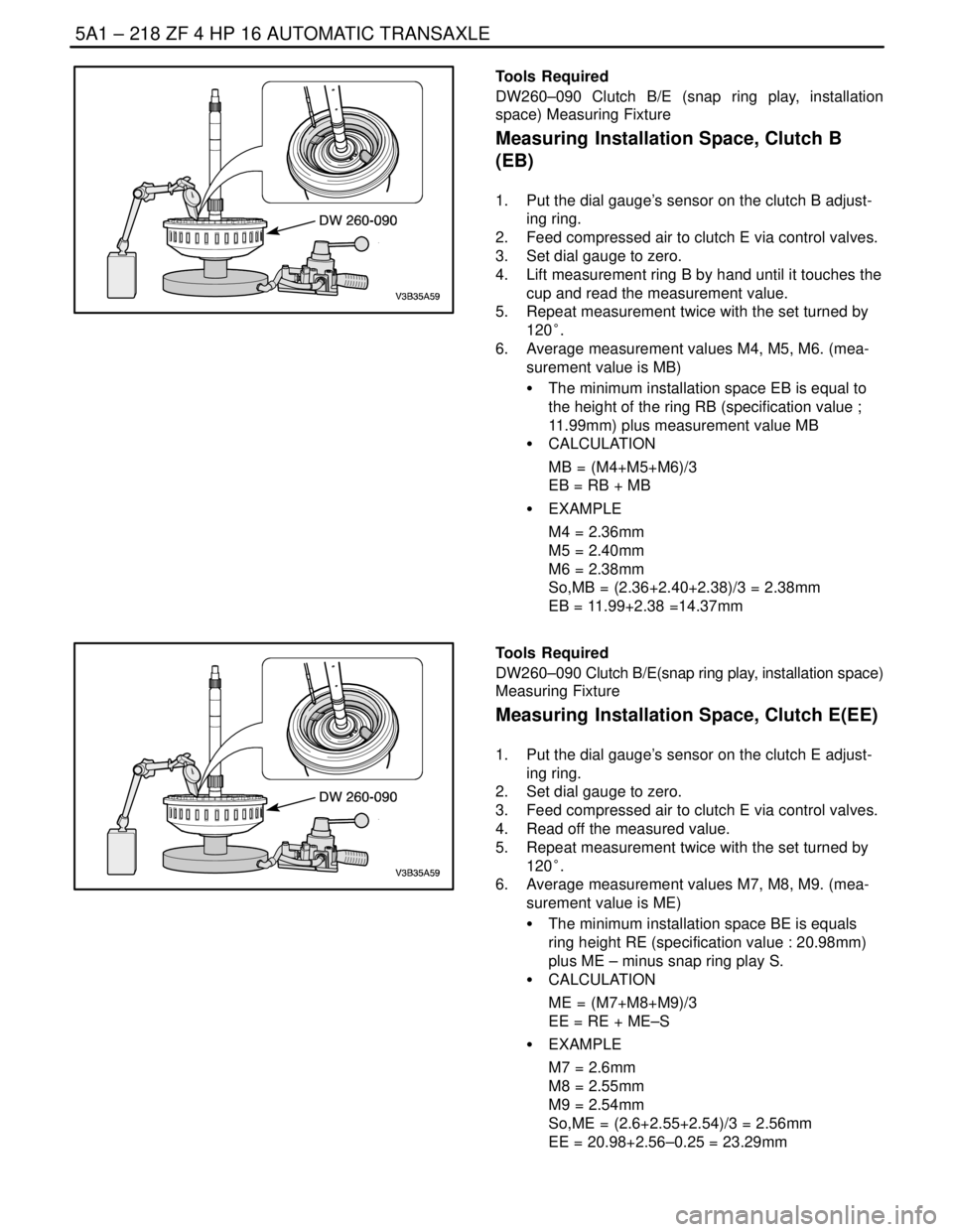
Tools Required
DW260–090 Clutch B/E(snap ring play, installation space)
Measuring Fixture
Determine Snap Ring Play
1. Put the dial gauge sensor on the clutch B adjusting
ring.
2. Feed compressed air to clutch B via control valves.
3. Set dial gauge to zero.
4. Pressurize clutch E via the control valve and read
measurement value.
5. Repeat measurement twice with disc set turned by
120°.
6. Average measurement values M1, M2, M3.(mea-
surement value is S)
S CALCULATION
S = (M1+M2+M3)/3
S EXAMPLE
– M1 = 0.27mm, M2 = 0.23mm, M3 = 0.25mm
– S = 0.25mm
Page 1567 of 2643

5A1 – 218IZF 4 HP 16 AUTOMATIC TRANSAXLE
DAEWOO V–121 BL4
Tools Required
DW260–090 Clutch B/E (snap ring play, installation
space) Measuring Fixture
Measuring Installation Space, Clutch B
(EB)
1. Put the dial gauge’s sensor on the clutch B adjust-
ing ring.
2. Feed compressed air to clutch E via control valves.
3. Set dial gauge to zero.
4. Lift measurement ring B by hand until it touches the
cup and read the measurement value.
5. Repeat measurement twice with the set turned by
120°.
6. Average measurement values M4, M5, M6. (mea-
surement value is MB)
S The minimum installation space EB is equal to
the height of the ring RB (specification value ;
11.99mm) plus measurement value MB
S CALCULATION
MB = (M4+M5+M6)/3
EB = RB + MB
S EXAMPLE
M4 = 2.36mm
M5 = 2.40mm
M6 = 2.38mm
So,MB = (2.36+2.40+2.38)/3 = 2.38mm
EB = 11.99+2.38 =14.37mm
Tools Required
DW260–090 Clutch B/E(snap ring play, installation space)
Measuring Fixture
Measuring Installation Space, Clutch E(EE)
1. Put the dial gauge’s sensor on the clutch E adjust-
ing ring.
2. Set dial gauge to zero.
3. Feed compressed air to clutch E via control valves.
4. Read off the measured value.
5. Repeat measurement twice with the set turned by
120°.
6. Average measurement values M7, M8, M9. (mea-
surement value is ME)
S The minimum installation space BE is equals
ring height RE (specification value : 20.98mm)
plus ME – minus snap ring play S.
S CALCULATION
ME = (M7+M8+M9)/3
EE = RE + ME–S
S EXAMPLE
M7 = 2.6mm
M8 = 2.55mm
M9 = 2.54mm
So,ME = (2.6+2.55+2.54)/3 = 2.56mm
EE = 20.98+2.56–0.25 = 23.29mm
Page 1568 of 2643

ZF 4 HP 16 AUTOMATIC TRANSAXLE 5A1 – 219
DAEWOO V–121 BL4
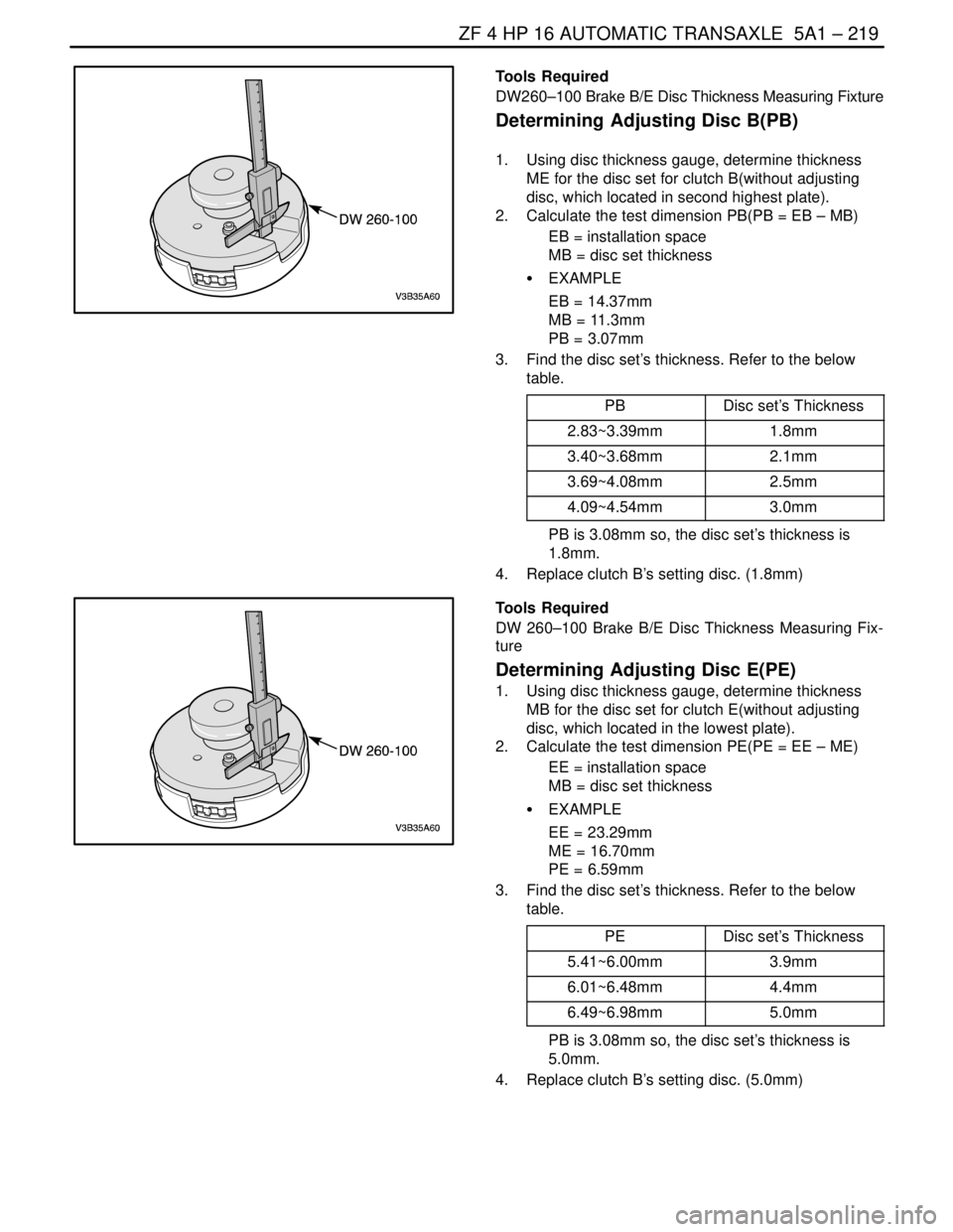
Tools Required
DW260–100 Brake B/E Disc Thickness Measuring Fixture
Determining Adjusting Disc B(PB)
1. Using disc thickness gauge, determine thickness
ME for the disc set for clutch B(without adjusting
disc, which located in second highest plate).
2. Calculate the test dimension PB(PB = EB – MB)
EB = installation space
MB = disc set thickness
S EXAMPLE
EB = 14.37mm
MB = 11.3mm
PB = 3.07mm
3. Find the disc set’s thickness. Refer to the below
table.
PB
Disc set’s Thickness
2.83~3.39mm1.8mm
3.40~3.68mm2.1mm
3.69~4.08mm2.5mm
4.09~4.54mm3.0mm
PB is 3.08mm so, the disc set’s thickness is
1.8mm.
4. Replace clutch B’s setting disc. (1.8mm)
Tools Required
DW 260–100 Brake B/E Disc Thickness Measuring Fix-
ture
Determining Adjusting Disc E(PE)
1. Using disc thickness gauge, determine thickness
MB for the disc set for clutch E(without adjusting
disc, which located in the lowest plate).
2. Calculate the test dimension PE(PE = EE – ME)
EE = installation space
MB = disc set thickness
S EXAMPLE
EE = 23.29mm
ME = 16.70mm
PE = 6.59mm
3. Find the disc set’s thickness. Refer to the below
table.
PE
Disc set’s Thickness
5.41~6.00mm3.9mm
6.01~6.48mm4.4mm
6.49~6.98mm5.0mm
PB is 3.08mm so, the disc set’s thickness is
5.0mm.
4. Replace clutch B’s setting disc. (5.0mm)
Page 1569 of 2643
5A1 – 220IZF 4 HP 16 AUTOMATIC TRANSAXLE
DAEWOO V–121 BL4
PLANETARY GEAR SET
Disassembly and Assembly Procedure
1. Remove the clutch B/E. Refer to ”Clutch B/E” in
this section.
2. Remove the rear sun gear.
3. Remove the planetary gear set.
4. Remove snap ring from front ring gear.
5. Take out rear planetary gear set.
Page 1572 of 2643
ZF 4 HP 16 AUTOMATIC TRANSAXLE 5A1 – 223
DAEWOO V–121 BL4
6. Remove cylinder with piston C.
7. Separate between piston C and cylinder C.
8. Take snap ring out of brake C.
9. Remove the disc set C.
Installation Notice
S Transaxle has two lined clutch discs and one
steel clutch disc. The lined discs must be
installed in such a way that the lining faces the
steel disc.
S Insert the fitting keys into the appropriate
grooves.