2004 DAEWOO LACETTI wheel
[x] Cancel search: wheelPage 153 of 2643
1.8L DOHC ENGINE MECHANICAL 1C2 – 33
DAEWOO V–121 BL4
Installation Procedure
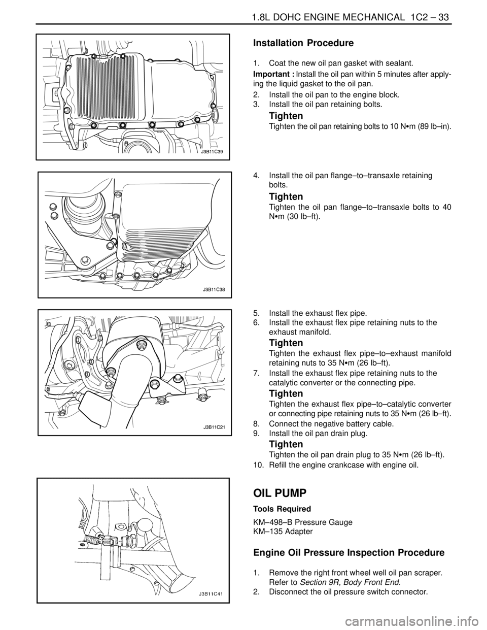
1. Coat the new oil pan gasket with sealant.
Important : Install the oil pan within 5 minutes after apply-
ing the liquid gasket to the oil pan.
2. Install the oil pan to the engine block.
3. Install the oil pan retaining bolts.
Tighten
Tighten the oil pan retaining bolts to 10 NSm (89 lb–in).
4. Install the oil pan flange–to–transaxle retaining
bolts.
Tighten
Tighten the oil pan flange–to–transaxle bolts to 40
NSm (30 lb–ft).
5. Install the exhaust flex pipe.
6. Install the exhaust flex pipe retaining nuts to the
exhaust manifold.
Tighten
Tighten the exhaust flex pipe–to–exhaust manifold
retaining nuts to 35 NSm (26 lb–ft).
7. Install the exhaust flex pipe retaining nuts to the
catalytic converter or the connecting pipe.
Tighten
Tighten the exhaust flex pipe–to–catalytic converter
or connecting pipe retaining nuts to 35 NSm (26 lb–ft).
8. Connect the negative battery cable.
9. Install the oil pan drain plug.
Tighten
Tighten the oil pan drain plug to 35 NSm (26 lb–ft).
10. Refill the engine crankcase with engine oil.
OIL PUMP
Tools Required
KM–498–B Pressure Gauge
KM–135 Adapter
Engine Oil Pressure Inspection Procedure
1. Remove the right front wheel well oil pan scraper.
Refer to Section 9R, Body Front End.
2. Disconnect the oil pressure switch connector.
Page 154 of 2643
1C2 – 34I1.8L DOHC ENGINE MECHANICAL
DAEWOO V–121 BL4
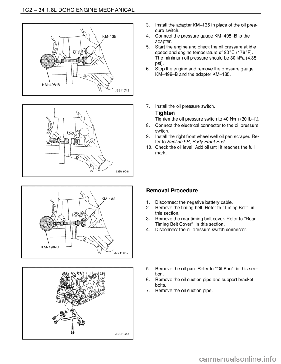
3. Install the adapter KM–135 in place of the oil pres-
sure switch.
4. Connect the pressure gauge KM–498–B to the
adapter.
5. Start the engine and check the oil pressure at idle
speed and engine temperature of 80°C (176°F).
The minimum oil pressure should be 30 kPa (4.35
psi).
6. Stop the engine and remove the pressure gauge
KM–498–B and the adapter KM–135.
7. Install the oil pressure switch.
Tighten
Tighten the oil pressure switch to 40 NSm (30 lb–ft).
8. Connect the electrical connector to the oil pressure
switch.
9. Install the right front wheel well oil pan scraper. Re-
fer to Section 9R, Body Front End.
10. Check the oil level. Add oil until it reaches the full
mark.
Removal Procedure
1. Disconnect the negative battery cable.
2. Remove the timing belt. Refer to ”Timing Belt” in
this section.
3. Remove the rear timing belt cover. Refer to ”Rear
Timing Belt Cover” in this section.
4. Disconnect the oil pressure switch connector.
5. Remove the oil pan. Refer to ”Oil Pan” in this sec-
tion.
6. Remove the oil suction pipe and support bracket
bolts.
7. Remove the oil suction pipe.
Page 166 of 2643

1C2 – 46I1.8L DOHC ENGINE MECHANICAL
DAEWOO V–121 BL4
7. Install the timing belt automatic tensioner and bolt.
8. Install the camshaft gears. Refer to ”Camshaft
Gears” in this section.
9. Install the timing belt and timing belt cover. Refer to
”Timing Belt” in this section.
10. Connect the negative battery cable.
ENGINE
Removal Procedure
1. Remove the fuel pump fuse.
2. Start the engine. After it stalls, crank the engine for
10 seconds to rid the fuel system of fuel pressure.
3. Remove the hood. Refer to Section 9R, Body Front
End.
4. Drain the engine oil.
5. Disconnect the negative battery cable.
6. Discharge the air conditioning (A/C) system, if
equipped. Refer to Section 7B, Manual Control
Heating, Ventilation, and Air Conditioning Systems.
7. Disconnect the manifold air temperature (MAT)
sensor connector.
8. Remove the air cleaner outlet hose from the throttle
body and air cleaner housing.
9. Disconnect the breather tubes from the camshaft
cover.
10. Remove the right front wheel. Refer to Section 2E,
Tires and Wheels.
11. Remove the right front wheel well splash shield.
Refer to Section 9R, Body Font End.
12. Remove the serpentine accessory drive belt. Refer
to Section 6B, Power Steering Pump.
13. Drain the engine coolant. Refer to Section 1D, En-
gine Cooling.
14. Remove the cooling system radiator and the engine
cooling fans. Refer to Section 1D, Engine Cooling.
15. Disconnect the upper radiator hose from the ther-
mostat housing.
16. Disconnect the power steering return hose from the
power steering pump.
17. Disconnect the power steering pressure hose from
the power steering pump.
18. Disconnect the electrical connector at the direct
ignition system (DIS) coil and the electronic control
module (ECM) ground terminal and at the starter
motor.
Page 170 of 2643
1C2 – 50I1.8L DOHC ENGINE MECHANICAL
DAEWOO V–121 BL4
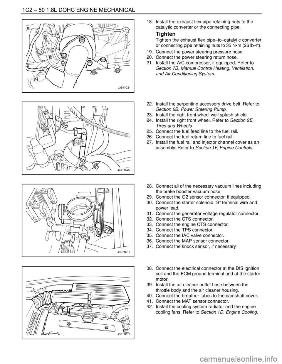
18. Install the exhaust flex pipe retaining nuts to the
catalytic converter or the connecting pipe.
Tighten
Tighten the exhaust flex pipe–to–catalytic converter
or connecting pipe retaining nuts to 35 NSm (26 lb–ft).
19. Connect the power steering pressure hose.
20. Connect the power steering return hose.
21. Install the A/C compressor, if equipped. Refer to
Section 7B, Manual Control Heating, Ventilation,
and Air Conditioning System.
22. Install the serpentine accessory drive belt. Refer to
Section 6B, Power Steering Pump.
23. Install the right front wheel well splash shield.
24. Install the right front wheel. Refer to Section 2E,
Tires and Wheels.
25. Connect the fuel feed line to the fuel rail.
26. Connect the fuel return line to fuel rail.
27. Install the fuel rail and injector channel cover as an
assembly. Refer to Section 1F, Engine Controls.
28. Connect all of the necessary vacuum lines including
the brake booster vacuum hose.
29. Connect the O2 sensor connector, if equipped.
30. Connect the starter solenoid ”S” terminal wire and
power lead.
31. Connect the generator voltage regulator connector.
32. Connect the CTS connector.
33. Connect the engine CTS connector.
34. Connect the TPS connector.
35. Connect the IAC valve connector.
36. Connect the MAP sensor connector.
37. Connect the knock sensor, if necessary
38. Connect the electrical connector at the DIS ignition
coil and the ECM ground terminal and at the starter
motor.
39. Install the air cleaner outlet hose between the
throttle body and the air cleaner housing.
40. Connect the breather tubes to the camshaft cover.
41. Connect the MAT sensor connector.
42. Install the cooling system radiator and the engine
cooling fans. Refer to Section 1D, Engine Cooling.
Page 183 of 2643
1.8L DOHC ENGINE MECHANICAL 1C2 – 63
DAEWOO V–121 BL4
31. Install the exhaust manifold studs.
32. Install the exhaust manifold gasket.
33. Install the exhaust manifold.
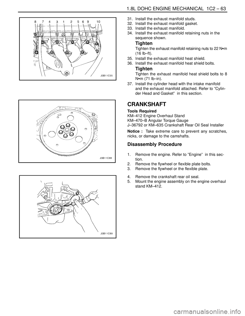
34. Install the exhaust manifold retaining nuts in the
sequence shown.
Tighten
Tighten the exhaust manifold retaining nuts to 22 NSm
(16 lb–ft).
35. Install the exhaust manifold heat shield.
36. Install the exhaust manifold heat shield bolts.
Tighten
Tighten the exhaust manifold heat shield bolts to 8
NSm (71 lb–in).
37. Install the cylinder head with the intake manifold
and the exhaust manifold attached. Refer to ”Cylin-
der Head and Gasket” in this section.
CRANKSHAFT
Tools Required
KM–412 Engine Overhaul Stand
KM–470–B Angular Torque Gauge
J–36792 or KM–635 Crankshaft Rear Oil Seal Installer
Notice : Take extreme care to prevent any scratches,
nicks, or damage to the camshafts.
Disassembly Procedure
1. Remove the engine. Refer to ”Engine” in this sec-
tion.
2. Remove the flywheel or flexible plate bolts.
3. Remove the flywheel or the flexible plate.
4. Remove the crankshaft rear oil seal.
5. Mount the engine assembly on the engine overhaul
stand KM–412.
Page 192 of 2643

1C2 – 72I1.8L DOHC ENGINE MECHANICAL
DAEWOO V–121 BL4
62. Install a new crankshaft rear oil seal using installer
J–36792 or KM–635.
63. Install the flywheel or flexible plate.
64. Install the flywheel or the flexible plate bolts.
Tighten
Tighten the flywheel bolts to 65 NSm (48 lb–ft). Use
the angular torque gauge KM–470–B to tighten the
flywheel bolts another 30 degrees plus 15 degrees.
For the automatic transmission, tighten the flexible
plate bolts to 45 NSm (33 lb–ft).
65. Install the engine. Refer to ”Engine” in this section.
CRANKSHAFT BEARINGS AND
CONNECTING ROD BEARINGS –
GAUGING PLASTIC
Tools Required
KM–470–B Angular Torque Gauge
Inspection Procedure – Crankshaft
1. Coat the crankshaft bearings with engine oil.
2. Install the upper crankshaft bearings into the engine
block crankshaft journals.
3. Install the lower crankshaft bearings into the crank-
shaft bearing caps.
4. Install the crankshaft.
5. Inspect the crankshaft end play with the crankshaft
bearings installed.
6. Check for permissible crankshaft end play. Refer to
”Engine Specifications” in this section.
Page 223 of 2643
ENGINE ELECTRICAL 1E – 9
DAEWOO V–121 BL4
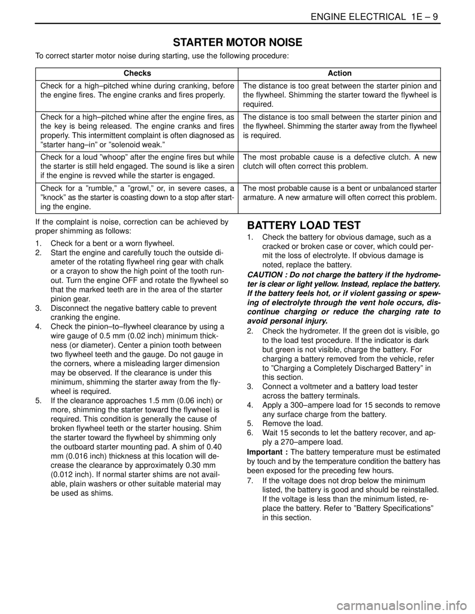
STARTER MOTOR NOISE
To correct starter motor noise during starting, use the following procedure:
Checks
Action
Check for a high–pitched whine during cranking, before
the engine fires. The engine cranks and fires properly.The distance is too great between the starter pinion and
the flywheel. Shimming the starter toward the flywheel is
required.
Check for a high–pitched whine after the engine fires, as
the key is being released. The engine cranks and fires
properly. This intermittent complaint is often diagnosed as
”starter hang–in” or ”solenoid weak.”The distance is too small between the starter pinion and
the flywheel. Shimming the starter away from the flywheel
is required.
Check for a loud ”whoop” after the engine fires but while
the starter is still held engaged. The sound is like a siren
if the engine is revved while the starter is engaged.The most probable cause is a defective clutch. A new
clutch will often correct this problem.
Check for a ”rumble,” a ”growl,” or, in severe cases, a
”knock” as the starter is coasting down to a stop after start-
ing the engine.The most probable cause is a bent or unbalanced starter
armature. A new armature will often correct this problem.
If the complaint is noise, correction can be achieved by
proper shimming as follows:
1. Check for a bent or a worn flywheel.
2. Start the engine and carefully touch the outside di-
ameter of the rotating flywheel ring gear with chalk
or a crayon to show the high point of the tooth run-
out. Turn the engine OFF and rotate the flywheel so
that the marked teeth are in the area of the starter
pinion gear.
3. Disconnect the negative battery cable to prevent
cranking the engine.
4. Check the pinion–to–flywheel clearance by using a
wire gauge of 0.5 mm (0.02 inch) minimum thick-
ness (or diameter). Center a pinion tooth between
two flywheel teeth and the gauge. Do not gauge in
the corners, where a misleading larger dimension
may be observed. If the clearance is under this
minimum, shimming the starter away from the fly-
wheel is required.
5. If the clearance approaches 1.5 mm (0.06 inch) or
more, shimming the starter toward the flywheel is
required. This condition is generally the cause of
broken flywheel teeth or the starter housing. Shim
the starter toward the flywheel by shimming only
the outboard starter mounting pad. A shim of 0.40
mm (0.016 inch) thickness at this location will de-
crease the clearance by approximately 0.30 mm
(0.012 inch). If normal starter shims are not avail-
able, plain washers or other suitable material may
be used as shims.BATTERY LOAD TEST
1. Check the battery for obvious damage, such as a
cracked or broken case or cover, which could per-
mit the loss of electrolyte. If obvious damage is
noted, replace the battery.
CAUTION : Do not charge the battery if the hydrome-
ter is clear or light yellow. Instead, replace the battery.
If the battery feels hot, or if violent gassing or spew-
ing of electrolyte through the vent hole occurs, dis-
continue charging or reduce the charging rate to
avoid personal injury.
2. Check the hydrometer. If the green dot is visible, go
to the load test procedure. If the indicator is dark
but green is not visible, charge the battery. For
charging a battery removed from the vehicle, refer
to ”Charging a Completely Discharged Battery” in
this section.
3. Connect a voltmeter and a battery load tester
across the battery terminals.
4. Apply a 300–ampere load for 15 seconds to remove
any surface charge from the battery.
5. Remove the load.
6. Wait 15 seconds to let the battery recover, and ap-
ply a 270–ampere load.
Important : The battery temperature must be estimated
by touch and by the temperature condition the battery has
been exposed for the preceding few hours.
7. If the voltage does not drop below the minimum
listed, the battery is good and should be reinstalled.
If the voltage is less than the minimum listed, re-
place the battery. Refer to ”Battery Specifications”
in this section.
Page 246 of 2643
1E – 32IENGINE ELECTRICAL
DAEWOO V–121 BL4
the same cable to the positive terminal on the other
battery. Never connect the other end to the nega-
tive terminal of the discharged battery.
CAUTION : To avoid injury do not attach the cable di-
rectly to the negative terminal of the discharged bat-
tery. Doing so could cause sparks and a possible bat-
tery explosion.
6. Clamp one end of the second cable to the negative
terminal of the booster battery. Make the final con-
nection to a solid engine ground (such as the en-
gine lift bracket) at least 450 millimeters (18 inches)
from the discharged battery.
7. Start the engine of the vehicle with the good bat-
tery. Run the engine at a moderate speed for sever-
al minutes. Then start the engine of the vehicle
which has the discharged battery.
8. Remove the jumper cables by reversing the above
sequence exactly. Remove the negative cable from
the vehicle with the discharged battery first. While
removing each clamp, take care that it does not
touch any other metal while the other end remains
attached.
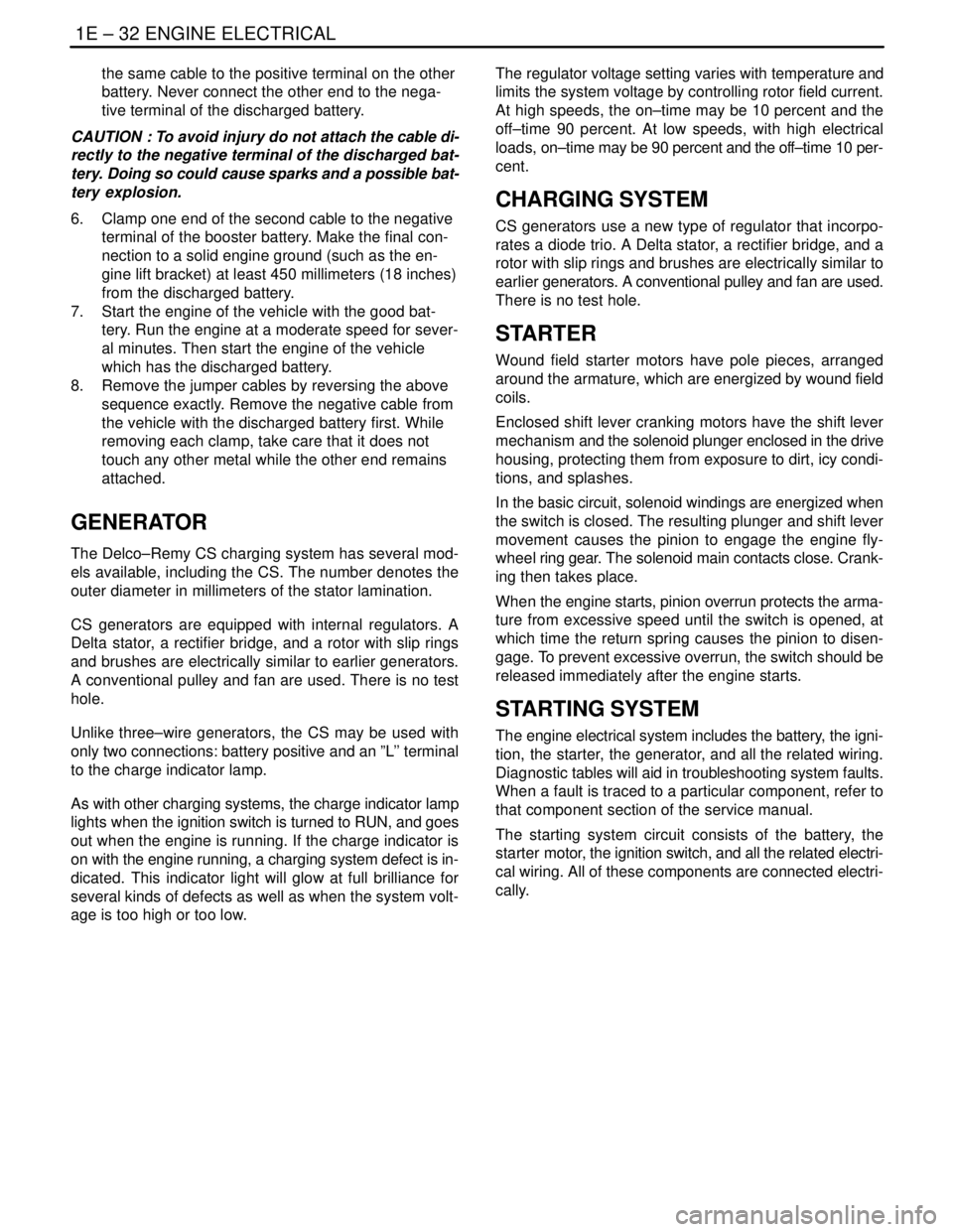
GENERATOR
The Delco–Remy CS charging system has several mod-
els available, including the CS. The number denotes the
outer diameter in millimeters of the stator lamination.
CS generators are equipped with internal regulators. A
Delta stator, a rectifier bridge, and a rotor with slip rings
and brushes are electrically similar to earlier generators.
A conventional pulley and fan are used. There is no test
hole.
Unlike three–wire generators, the CS may be used with
only two connections: battery positive and an ”L’’ terminal
to the charge indicator lamp.
As with other charging systems, the charge indicator lamp
lights when the ignition switch is turned to RUN, and goes
out when the engine is running. If the charge indicator is
on with the engine running, a charging system defect is in-
dicated. This indicator light will glow at full brilliance for
several kinds of defects as well as when the system volt-
age is too high or too low.The regulator voltage setting varies with temperature and
limits the system voltage by controlling rotor field current.
At high speeds, the on–time may be 10 percent and the
off–time 90 percent. At low speeds, with high electrical
loads, on–time may be 90 percent and the off–time 10 per-
cent.
CHARGING SYSTEM
CS generators use a new type of regulator that incorpo-
rates a diode trio. A Delta stator, a rectifier bridge, and a
rotor with slip rings and brushes are electrically similar to
earlier generators. A conventional pulley and fan are used.
There is no test hole.
STARTER
Wound field starter motors have pole pieces, arranged
around the armature, which are energized by wound field
coils.
Enclosed shift lever cranking motors have the shift lever
mechanism and the solenoid plunger enclosed in the drive
housing, protecting them from exposure to dirt, icy condi-
tions, and splashes.
In the basic circuit, solenoid windings are energized when
the switch is closed. The resulting plunger and shift lever
movement causes the pinion to engage the engine fly-
wheel ring gear. The solenoid main contacts close. Crank-
ing then takes place.
When the engine starts, pinion overrun protects the arma-
ture from excessive speed until the switch is opened, at
which time the return spring causes the pinion to disen-
gage. To prevent excessive overrun, the switch should be
released immediately after the engine starts.
STARTING SYSTEM
The engine electrical system includes the battery, the igni-
tion, the starter, the generator, and all the related wiring.
Diagnostic tables will aid in troubleshooting system faults.
When a fault is traced to a particular component, refer to
that component section of the service manual.
The starting system circuit consists of the battery, the
starter motor, the ignition switch, and all the related electri-
cal wiring. All of these components are connected electri-
cally.