2004 DAEWOO LACETTI Steering pump
[x] Cancel search: Steering pumpPage 171 of 2643
1.8L DOHC ENGINE MECHANICAL 1C2 – 51
DAEWOO V–121 BL4
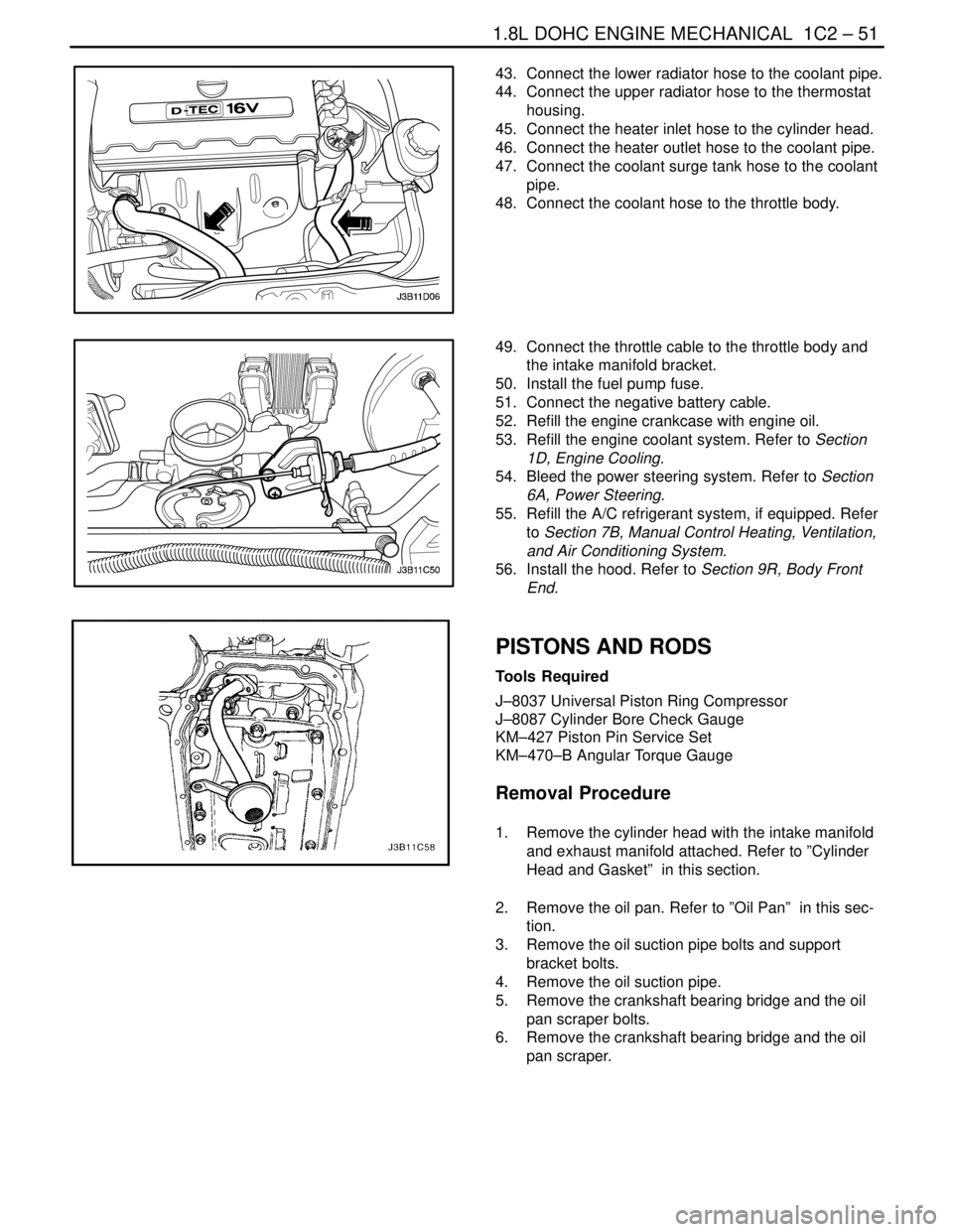
43. Connect the lower radiator hose to the coolant pipe.
44. Connect the upper radiator hose to the thermostat
housing.
45. Connect the heater inlet hose to the cylinder head.
46. Connect the heater outlet hose to the coolant pipe.
47. Connect the coolant surge tank hose to the coolant
pipe.
48. Connect the coolant hose to the throttle body.
49. Connect the throttle cable to the throttle body and
the intake manifold bracket.
50. Install the fuel pump fuse.
51. Connect the negative battery cable.
52. Refill the engine crankcase with engine oil.
53. Refill the engine coolant system. Refer to Section
1D, Engine Cooling.
54. Bleed the power steering system. Refer to Section
6A, Power Steering.
55. Refill the A/C refrigerant system, if equipped. Refer
to Section 7B, Manual Control Heating, Ventilation,
and Air Conditioning System.
56. Install the hood. Refer to Section 9R, Body Front
End.
PISTONS AND RODS
Tools Required
J–8037 Universal Piston Ring Compressor
J–8087 Cylinder Bore Check Gauge
KM–427 Piston Pin Service Set
KM–470–B Angular Torque Gauge
Removal Procedure
1. Remove the cylinder head with the intake manifold
and exhaust manifold attached. Refer to ”Cylinder
Head and Gasket” in this section.
2. Remove the oil pan. Refer to ”Oil Pan” in this sec-
tion.
3. Remove the oil suction pipe bolts and support
bracket bolts.
4. Remove the oil suction pipe.
5. Remove the crankshaft bearing bridge and the oil
pan scraper bolts.
6. Remove the crankshaft bearing bridge and the oil
pan scraper.
Page 225 of 2643
ENGINE ELECTRICAL 1E – 11
DAEWOO V–121 BL4
MAINTENANCE AND REPAIR
ON–VEHICLE SERVICE
GENERATOR
Removal Procedure
1. Disconnect the negative battery cable.
2. Disconnect the manifold air temperature (MAT)
sensor electrical connector the air intake tube.
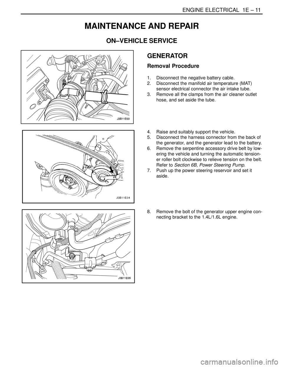
3. Remove all the clamps from the air cleaner outlet
hose, and set aside the tube.
4. Raise and suitably support the vehicle.
5. Disconnect the harness connector from the back of
the generator, and the generator lead to the battery.
6. Remove the serpentine accessory drive belt by low-
ering the vehicle and turning the automatic tension-
er roller bolt clockwise to relieve tension on the belt.
Refer to Section 6B, Power Steering Pump.
7. Push up the power steering reservoir and set it
aside.
8. Remove the bolt of the generator upper engine con-
necting bracket to the 1.4L/1.6L engine.
Page 227 of 2643
ENGINE ELECTRICAL 1E – 13
DAEWOO V–121 BL4
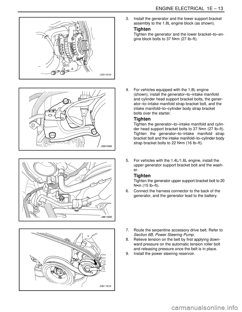
3. Install the generator and the lower support bracket
assembly to the 1.8L engine block (as shown).
Tighten
Tighten the generator and the lower bracket–to–en-
gine block bolts to 37 NSm (27 lb–ft).
4. For vehicles equipped with the 1.8L engine
(shown), install the generator–to–intake manifold
and cylinder head support bracket bolts, the gener-
ator–to–intake manifold strap bracket bolt, and the
intake manifold–to–cylinder body strap bracket
bolts over the starter.
Tighten
Tighten the generator–to–intake manifold and cylin-
der head support bracket bolts to 37 NSm (27 lb–ft).
Tighten the generator–to–intake manifold strap
bracket bolt and the intake manifold–to–cylinder body
strap bracket bolts to 22 NSm (16 lb–ft).
5. For vehicles with the 1.4L/1.6L engine, install the
upper generator support bracket bolt and the wash-
er.
Tighten
Tighten the generator upper support bracket bolt to 20
NSm (15 lb–ft).
6. Connect the harness connector to the back of the
generator, and the generator lead to the battery.
7. Route the serpentine accessory drive belt. Refer to
Section 6B, Power Steering Pump.
8. Relieve tension on the belt by first applying down-
ward pressure on the automatic tension roller bolt
and releasing pressure once the belt is in place.
9. Install the power steering reservoir.
Page 862 of 2643

1F – 616IENGINE CONTROLS
DAEWOO V–121 BL4
3. Remove the crankshaft position sensor (CKP) bolt.
4. Remove the CKP sensor.
Installation Procedure
1. Install the CKP sensor with the bolt.
Tighten
Tighten the crankshaft position sensor (CKP) bolt to
6.5 NSm (57 lb–in).
2. Connect the CKP sensor electrical connector.
3. Connect the negative battery cable.
CRANKSHAFT POSITION (CKP)
SENSOR (1.8L DOHC)
Removal Procedure
1. Disconnect the negative battery cable.
2. Remove the power steering pump, if equipped. Re-
fer to Section 6B, Power Steering Pump.
3. Remove the A/C compressor. Refer to Section 7D,
Automatic Temperature Control Heating, Ventilation
and Air Conditioning System.
4. Remove the rear A/C compressor mounting bracket
bolts and the rear A/C compressor mounting brack-
et.
Page 863 of 2643

ENGINE CONTROLS 1F – 617
DAEWOO V–121 BL4
5. Remove the accessory mounting bracket by remov-
ing the bolts.
6. Disconnect the crankshaft position (CKP) sensor
connector.
7. Remove the CKP sensor retaining bolt.
8. Gently rotate and remove the CKP sensor from the
engine block.
Installation Procedure
1. Insert the CKP sensor into the engine block.
2. Install the CKP sensor retaining bolt.
Tighten
Tighten the crankshaft position sensor retaining bolt
to 8 NSm (71 lb–in).
3. Connect the CKP sensor connector.
4. Install the accessory mounting bracket with the
bolts.
Tighten
Tighten the accessory mounting bracket bolts to 27
NSm (37 lb–ft).
5. Install the rear A/C mounting bracket.
Tighten
Tighten the rear A/C mounting bracket bolts to 35
NSm (26 lb–ft).
6. Install the A/C compressor. Refer to Section 7D,
Automatic Temperature Control Heating, Ventilation
and Air Conditioning System.
7. Install the power steering pump. Refer to Section
6B, Power Steering Pump.
8. Connect the negative battery cable.
Page 902 of 2643

SECTION : 2A
SUSPENSION DIAGNOSIS
TABLE OF CONTENTS
DIAGNOSIS2A–1 . . . . . . . . . . . . . . . . . . . . . . . . . . . . . . . .
General Diagnosis 2A–1. . . . . . . . . . . . . . . . . . . . . . . . . Torque Steer 2A–5. . . . . . . . . . . . . . . . . . . . . . . . . . . . . .
Tapered Roller Bearing 2A–6. . . . . . . . . . . . . . . . . . . . .
DIAGNOSIS
GENERAL DIAGNOSIS
Problems in the steering, the suspension, the tires, and
the wheels involve several systems. Consider all systems
when diagnosing a complaint. Some problems, such as
abnormal or excessive tire wear and scuffed tires, may be
the result of hard driving. Always road test the vehicle first.If possible, do this road test with the customer.
Proceed with the following preliminary checks. Correct
any substandard conditions.
Preliminary Checks
ChecksAction
Inspect the tires for improper pressure and uneven wear.Inflate the tires to the proper pressure.
Inspect the joint from the steering column to the steering
gear for loose connections or wear.Tighten the intermediate shaft pinch bolts. Replace the in-
termediate shaft as needed.
Inspect the front and the rear suspension, the steering
gear, and the linkage for loose or damaged parts.Tighten the front and the rear suspension. Tighten the
steering gear mounting bracket bolts. Tighten the coupling
flange pinch bolts. Replace the front and the rear suspen-
sion as needed. Replace the steering gear as needed. Re-
place the intermediate shaft as needed.
Inspect for out–of–round tires.Perform a free runout test. Match–mount the tires.
Inspect for out–of–balance tires, bent wheels, and worn or
loose wheel bearings.Balance the wheels. Replace the wheels. Replace the
wheel bearings.
Check the power steering pump serpentine belt tension.Tighten the power steering pump serpentine belt.
Inspect the power steering system for leaks. Check the
power steering fluid level.Repair any leaks. Perform a power steering gear test. Add
power steering fluid.
Car Lead/Pull
ChecksAction
Inspect for mismatched or uneven tires.Replace the tires.
Inspect for a broken or a sagging spring.Replace the spring.
Inspect for a radial tire lateral force.Check the wheel alignment. Switch the wheels. Replace
the tires as needed.
Check the front–wheel alignment.Align the front wheels.
Inspect for an off–center steering gear.Reseat the pinion valve assembly. Replace the pinion
valve assembly as needed.
Inspect for front–brake dragging.Adjust the front brakes.
Page 906 of 2643

SUSPENSION DIAGNOSIS 2A – 5
DAEWOO V–121 BL4
Steering Wheel Kickback
ChecksAction
Inspect for air in the power steering system.Purge the power steering system of air.
Inspect for a loose steering gear mounting.Tighten the steering gear mounting bracket nuts.
Inspect the joint from the column to the steering gear for
loose connections or wear.Tighten the intermediate shaft pinch bolts. Replace the in-
termediate shaft as needed.
Inspect for loose tie rod ends.Tighten the tie rod ends. Replace the outer tie rods as
needed.
Inspect for loose or worn wheel bearings.Tighten the drive axle nut. Replace the wheel bearings as
needed.
Steering Wheel Surges or Jerks
ChecksAction
Check the hydraulic system. Test the power steering sys-
tem pressure with a gauge.Replace the seals and the hoses as needed.
Inspect for a sluggish steering gear valve.Clean the pinion valve assembly. Replace the pinion valve
assembly as needed.
Inspect for a loose power steering pump serpentine belt.Adjust the power steering pump serpentine belt.
Cupped Tires
ChecksAction
Check the front–wheel and the rear–wheel alignment.Align the front and the rear wheels.
Inspect for worn strut dampeners.Replace the strut dampeners.
Inspect for worn or loose wheel bearings.Tighten the drive axle nut. Replace the wheel bearings as
needed.
Inspect for excessive tire or wheel runout.Match–mount the tires. Replace the tires as needed. Re-
place the wheels as needed.
Inspect for a worn ball joint.Replace the ball joint.
Check the steering gear preload adjustment.Perform a rack bearing preload adjustment.
TORQUE STEER
A degree of torque steer to the right may be experienced
during the use of heavy throttle on some front–wheel drive
cars with drive axles of unequal length. This torque steer
to the right results from the right drive axle being longer
than the left drive axle, which creates a difference in the
drive axle angle. Cars with intermediate shaft assemblies
have axles of almost equal length.
A difference in the drive axle lengths results in more torque
toe–in in the left front wheel. You will notice the torque toe–
in when the vehicle accelerates from a standing start or at
lower speeds.
Inspection Procedure
1. Place a small piece of tape at the top center of the
steering wheel.2. Note the inches of steering wheel deflection re-
quired to keep the vehicle straight during heavy ac-
celeration.
3. Compare this finding with similar cars.
Factors that may cause torque steer to be more apparent
on a particular vehicle include:
S Variations in the tire and wheel assemblies. This
has the most significant effect on torque steer. A
slightly smaller diameter on the right front tire will
increase a right torque lead.
S Large differences in the right and the left front tire
pressure.
S Looseness in the control arm bushings, the tie rod
assemblies, or the steering gear mounting. This
looseness permits a front wheel to pull forward and
toe–in under a torque greater than the wheel on the
opposite side. A loose suspension component may
result in an opposite lead upon deceleration.
Page 1152 of 2643

ANTILOCK BRAKE SYSTEM 4F – 71
DAEWOO V–121 BL4
TIRES AND ABS/EBD
Replacement Tires
Tire size is important for proper performance of the ABS
system. Replacement tires should be the same size, load
range, and construction as the original tires. Replace tires
in axle sets and only with tires of the same tire perfor-
mance criteria (TPC) specification number. Use of any
other size or type may seriously affect the ABS operation.
TIRES AND ABS/EBD
Notice : There is no serviceable or removable EEPROM.
The EBCM must be replaced as an assembly.
The EBCM is attached to the hydraulic unit in the engine
compartment. The controlling element of ABS 5.3 is a mi-
croprocessor–based EBCM. Inputs to the system include
the four wheel speed sensors, the stoplamp switch, the
ignition switch, and the unswitched battery voltage. There
is an output to a bi–directional serial data link, located in
pin K of Data Link Connector (DLC) for service diagnostic
tools and assembly plant testing.
The EBCM monitors the speed of each wheel. If any wheel
begins to approach lockup and the brake switch is closed
(brake pedal depressed), the EBCM controls the sole-
noids to reduce brake pressure to the wheel approaching
lockup. Once the wheel regains traction, brake pressure
is increased until the wheel again begins to approach lock-
up. This cycle repeats until either the vehicle comes to a
stop, the brake pedal is released, or no wheels approach
lockup.
Additionally, the EBCM monitors itself, each input (except
the serial data link), and each output for proper operation.
If it detects any system malfunction, the EBCM will store
a DTC in nonvolatile memory (EEPROM) (DTCs will not
disappear if the battery is disconnected). Refer to ”Self
Diagnostics” in this section for more detailed information.
FRONT WHEEL SPEED SENSOR
The front wheel speed sensors are of a variable reluctance
type. Each sensor is attached to the steering knuckle,
close to a toothed ring. The result, as teeth pass by the
sensor, is an AC voltage with a frequency proportional to
the speed of the wheel. The magnitude of the voltage and
frequency increase with increasing speed. The sensor is
not repairable, nor is the air gap adjustable.
FRONT WHEEL SPEED SENSOR
RINGS
The toothed ring mentioned above is pressed onto the
wheel–side (outer) constant velocity joint. Each ring con-
tains 47 equally spaced teeth. Exercise care during ser-
vice procedures to avoid prying or contacting this ring. Ex-cessive contact may cause damage to one or more teeth.
If the ring is damaged, the wheel–side constant velocity
joint must be replaced.
REAR WHEEL SPEED SENSOR AND
RINGS
The rear wheel speed sensors operate in the same man-
ner as the front wheel speed sensors. They incorporate a
length of flexible harness with the connector attached to
the end of the harness. The rear wheel speed rings are in-
corporated into the hub assemblies and cannot be re-
placed separately, but require replacement of the rear
hub/bearing assembly.
VALUE RELAY AND PUMP MOTOR
RELAY
The valve relay and the motor pump relay are located in-
side the electronic brake control module (EBCM) and are
not replaceable. If one should fail, replace the EBCM.
WIRING HARNESS
The wiring harness is the mechanism by which the elec-
tronic brake control module (EBCM) is electrically con-
nected to power and to ground, to the wheel speed sen-
sors, the fuses, the switches, the indicators, and the serial
communications port. The components, considered part
of the wiring harness, are the wires that provide electrical
interconnection, and connectors (terminals, pins, con-
tacts, or lugs) that provide an electrical/mechanical inter-
face from the wire to a system component.
INDICATORS
The electronic brake control module (EBCM) continuously
monitors itself and the other ABS components. If the
EBCM detects a problem with the system, the amber ABS
indicator will light continuously to alert the driver to the
problem. An illuminated ABS indicator indicates that the
ABS system has detected a problem that affects the op-
eration of ABS. No antilock braking will be available. Nor-
mal, non–antilock brake performance will remain. In order
to regain ABS braking ability, the ABS must be serviced.
The red BRAKE indicator will be illuminated when the sys-
tem detects a low brake fluid level in the master cylinder
or when the parking brake switch is closed (the parking
brake is engaged) or EBD system is diabled.
WARNING : EBD INDICATOR LAMP WIRING IS CON-
NECTED TO THE PARKING BRAKE LAMP. IF THE
PARKING BRAKE LAMP IS TURNED ON WHEN YOU
DRIVING, CHECKING ON WHETHER THE PARKING
BRAKE LEVER IS ENAGED OR THE BRAKE FLUID
LEVEL IS LOW. IF THE SYSTEM HAS NO PROBLEM,
THE EBD SYSTEM IS WORKING IMPROPERLY. THE
EBD SYSTEM MUST BE SERVICED.