2004 DAEWOO LACETTI diagram
[x] Cancel search: diagramPage 1975 of 2643

SECTION : 7A
HEATING AND VENTILATION SYSTEM
CAUTION : Disconnect the negative battery cable before removing or installing any electrical unit or when a tool
or equipment could easily come in contact with exposed electrical terminals. Disconnecting this cable will help
prevent personal injury and damage to the vehicle. The ignition must also be in LOCK unless otherwise noted.
TABLE OF CONTENTS
SPECIFICATIONS7A–1 . . . . . . . . . . . . . . . . . . . . . . . . . .
Heater Temperature Specifications 7A–1. . . . . . . . . . .
Fastener Tightening Specifications 7A–1. . . . . . . . . . .
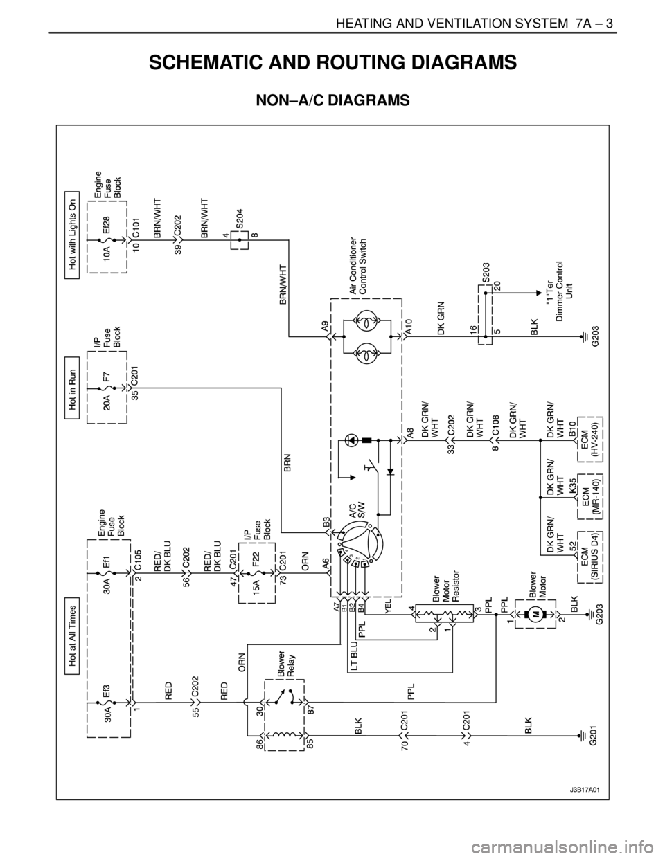
SCHEMATIC AND ROUTING DIAGRAMS7A–3 . . . . .
Non–A/C Diagrams 7A–3. . . . . . . . . . . . . . . . . . . . . . . .
Airflow – Typical 7A–4. . . . . . . . . . . . . . . . . . . . . . . . . . .
Airflow with Rear Heating Duct 7A–5. . . . . . . . . . . . . .
DIAGNOSIS7A–6 . . . . . . . . . . . . . . . . . . . . . . . . . . . . . . . .
HEATER SYSTEM 7A–6. . . . . . . . . . . . . . . . . . . . . . . . . .
Insufficient Heating or Defrosting 7A–6. . . . . . . . . . . . .
Blower Electrical 7A–9. . . . . . . . . . . . . . . . . . . . . . . . . . .
Improper Air delivery or No Mode Shift 7A–11. . . . . .
Too Much Heat 7A–13. . . . . . . . . . . . . . . . . . . . . . . . . . .
Controls 7A–15. . . . . . . . . . . . . . . . . . . . . . . . . . . . . . . . .
Blower Noise 7A–16. . . . . . . . . . . . . . . . . . . . . . . . . . . . . MAINTENANCE AND REPAIR7A–18 . . . . . . . . . . . . . .
ON–VEHICLE SERVICE 7A–18. . . . . . . . . . . . . . . . . . . .
Temperature Cable Adjustment 7A–18. . . . . . . . . . . . .
Temperature Control Cable 7A–18. . . . . . . . . . . . . . . . .
Control Assembly 7A–20. . . . . . . . . . . . . . . . . . . . . . . . .
Control Assembly Knob Lighting 7A–21. . . . . . . . . . . .
Heater/Air Distributor Case Assembly 7A–21. . . . . . .
Blower Motor 7A–23. . . . . . . . . . . . . . . . . . . . . . . . . . . . .
High–Blower Relay 7A–24. . . . . . . . . . . . . . . . . . . . . . . .
Blower Resistor 7A–25. . . . . . . . . . . . . . . . . . . . . . . . . .
Heater Hoses 7A–25. . . . . . . . . . . . . . . . . . . . . . . . . . . .
Heater Core 7A–26. . . . . . . . . . . . . . . . . . . . . . . . . . . . . .
GENERAL DESCRIPTION AND SYSTEM
OPERATION7A–28 . . . . . . . . . . . . . . . . . . . . . . . . . . . . .
Heating and Ventilation Systems 7A–28. . . . . . . . . . . .
SPECIFICATIONS
HEATER TEMPERATURE SPECIFICATIONS
Ambient Air TemperatureHeater Outlet Air Temperature
–18°C (0°F)54°C (129°F)
– 4°C (25°F)59°C (138°F)
10°C (50°F)64°C (147°F)
24°C (75°F)68°C (154°F)
FASTENER TIGHTENING SPECIFICATIONS
ApplicationNSmLb–FtLb–In
Blower Motor–to–A/C Assembly Screws1.2–11
Blower Motor Resistor Screws1.2–11
Blower Motor Retaining Screws1.2–11
Controller Retaining Screws2–18
Heater/Air Distributor Case Assembly Screw4–35
Page 1977 of 2643
HEATING AND VENTILATION SYSTEM 7A – 3
DAEWOO V–121 BL4
SCHEMATIC AND ROUTING DIAGRAMS
NON–A/C DIAGRAMS
Page 2003 of 2643

SECTION : 7B
MANUAL CONTROL HEATING, VENTILATION
AND AIR CONDITIONING SYSTEM
CAUTION : Disconnect the negative battery cable before removing or installing any electrical unit or when a tool
or equipment could easily come in contact with exposed electrical terminals. Disconnecting this cable will help
prevent personal injury and damage to the vehicle. The ignition must also be in LOCK unless otherwise noted.
TABLE OF CONTENTS
SPECIFICATIONS7B–2 . . . . . . . . . . . . . . . . . . . . . . . . . .
General Specifications 7B–2. . . . . . . . . . . . . . . . . . . . .
Fastener Tightening Specifications 7B–2. . . . . . . . . . .
SPECIAL TOOLS7B–3 . . . . . . . . . . . . . . . . . . . . . . . . . . .
Special Tools Table 7B–3. . . . . . . . . . . . . . . . . . . . . . . .
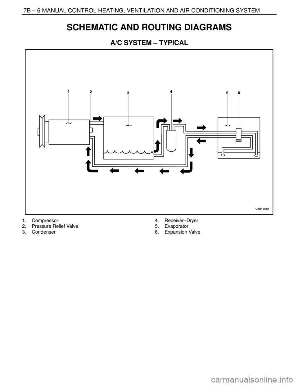
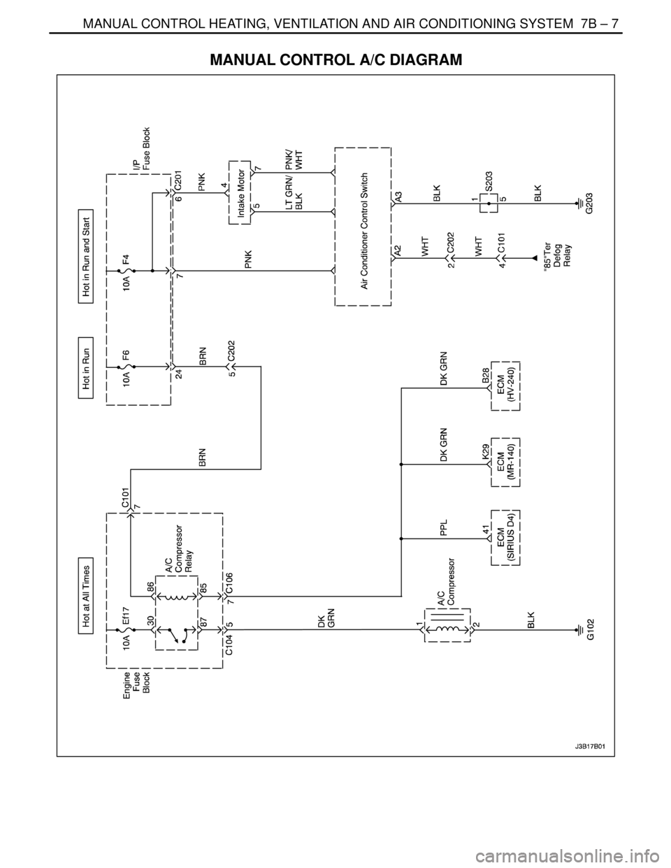
SCHEMATIC AND ROUTING DIAGRAMS7B–6 . . . . .
A/C System – Typical 7B–6. . . . . . . . . . . . . . . . . . . . . .
Manual Control A/C Diagram 7B–7. . . . . . . . . . . . . . . .
DIAGNOSIS7B–8 . . . . . . . . . . . . . . . . . . . . . . . . . . . . . . . .
GENERAL DIAGNOSIS 7B–8. . . . . . . . . . . . . . . . . . . . . .
Testing the Refrigerant System 7B–8. . . . . . . . . . . . . .
Insufficient Cooling ”Quick Check” Procedure 7B–8. .
A/C Performance Test 7B–9. . . . . . . . . . . . . . . . . . . . . .
Pressure–Temperature Relationship of
R–134A 7B–10. . . . . . . . . . . . . . . . . . . . . . . . . . . . . . .
Leak Testing Refrigerant System 7B–11. . . . . . . . . . . .
V5 SYSTEM AIR CONDITIONING DIAGNOSIS 7B–12
Insufficient Cooling Diagnosis 7B–12. . . . . . . . . . . . . .
SYMPTOM DIAGNOSIS 7B–16. . . . . . . . . . . . . . . . . . . .
Pressure Test Chart (R–134A System) 7B–16. . . . . .
Low and High Side Pressure Relationship
Chart 7B–18. . . . . . . . . . . . . . . . . . . . . . . . . . . . . . . . . .
MAINTENANCE AND REPAIR7B–19 . . . . . . . . . . . . . .
ON–VEHICLE SERVICE 7B–19. . . . . . . . . . . . . . . . . . . .
GENERAL A/C SYSTEM SERVICE
PROCEDURES 7B–19. . . . . . . . . . . . . . . . . . . . . . . . . .
O–Ring Replacement 7B–19. . . . . . . . . . . . . . . . . . . . .
Handling Refrigerant 7B–19. . . . . . . . . . . . . . . . . . . . . .
Handling of Refrigerant Lines and Fittings 7B–19. . . .
Maintaining Chemical Stability in the Refrigeration
System 7B–20. . . . . . . . . . . . . . . . . . . . . . . . . . . . . . . .
Discharging, Adding Oil, Evacuating, and Charging
Procedures for A/C System 7B–20. . . . . . . . . . . . . .
SERVICEABLE COMPONENTS 7B–23. . . . . . . . . . . . . Components Used In Non–A/C Systems 7B–23. . . . .
A/C Pressure Transducer 7B–24. . . . . . . . . . . . . . . . . .
A/C Compressor Relay 7B–24. . . . . . . . . . . . . . . . . . . .
Air Filter 7B–25. . . . . . . . . . . . . . . . . . . . . . . . . . . . . . . . .
A/C Expansion Valve 7B–25. . . . . . . . . . . . . . . . . . . . . .
A/C High–Pressure Pipe Line 7B–26. . . . . . . . . . . . . . .
Evaporator Core 7B–29. . . . . . . . . . . . . . . . . . . . . . . . . .
A/C Suction Hose Assembly 7B–30. . . . . . . . . . . . . . .
A/C Discharge Hose Compressor to
Condenser 7B–31. . . . . . . . . . . . . . . . . . . . . . . . . . . . .
Receiver–Dryer 7B–32. . . . . . . . . . . . . . . . . . . . . . . . . . .
Compressor 7B–33. . . . . . . . . . . . . . . . . . . . . . . . . . . . . .
Condenser 7B–35. . . . . . . . . . . . . . . . . . . . . . . . . . . . . . .
UNIT REPAIR 7B–37. . . . . . . . . . . . . . . . . . . . . . . . . . . . .
COMPONENT LOCATOR 7B–37. . . . . . . . . . . . . . . . . . .
V5 Compressor 7B–37. . . . . . . . . . . . . . . . . . . . . . . . . . .
V5 AIR CONDITIONING COMPRESSOR
OVERHAUL 7B–38. . . . . . . . . . . . . . . . . . . . . . . . . . . . .
Clutch Plate and Hub Assembly 7B–38. . . . . . . . . . . .
Clutch Rotor and Bearing 7B–40. . . . . . . . . . . . . . . . . .
Clutch Coil 7B–42. . . . . . . . . . . . . . . . . . . . . . . . . . . . . . .
Shaft Seal Replacement 7B–44. . . . . . . . . . . . . . . . . . .
Control Valve Assembly 7B–46. . . . . . . . . . . . . . . . . . .
Rear Head, Gasket, Valve Plate, Reed Plate,
and O–ring 7B–47. . . . . . . . . . . . . . . . . . . . . . . . . . . . .
Cylinder to Front Head O–ring 7B–48. . . . . . . . . . . . . .
Leak Testing (External) 7B–50. . . . . . . . . . . . . . . . . . . .
GENERAL DESCRIPTION AND SYSTEM
OPERATION7B–51 . . . . . . . . . . . . . . . . . . . . . . . . . . . . .
GENERAL INFORMATION 7B–51. . . . . . . . . . . . . . . . . .
The V5 A/C System 7B–51. . . . . . . . . . . . . . . . . . . . . . .
System Components – Functional 7B–51. . . . . . . . . .
System Components – Control 7B–52. . . . . . . . . . . . .
V5 Compressor – General Description 7B–52. . . . . . .
V5 Compressor – Description of Operation 7B–52. . .
Page 2008 of 2643
7B – 6IMANUAL CONTROL HEATING, VENTILATION AND AIR CONDITIONING SYSTEM
DAEWOO V–121 BL4
SCHEMATIC AND ROUTING DIAGRAMS
A/C SYSTEM – TYPICAL
1. Compressor
2. Pressure Relief Valve
3. Condenser4. Receiver–Dryer
5. Evaporator
6. Expansion Valve
Page 2009 of 2643
MANUAL CONTROL HEATING, VENTILATION AND AIR CONDITIONING SYSTEM 7B – 7
DAEWOO V–121 BL4
MANUAL CONTROL A/C DIAGRAM
Page 2056 of 2643

SECTION : 7D
AUTOMATIC TEMPERATURE CONTROL
HEATING, VENTILATION, AND AIR
CONDITIONING SYSTEM
CAUTION : Disconnect the negative battery cable before removing or installing any electrical unit or when a tool
or equipment could easily come in contact with exposed electrical terminals. Disconnecting this cable will help
prevent personal injury and damage to the vehicle. The ignition must also be in LOCK unless otherwise noted.
TABLE OF CONTENTS
SPECIFICATIONS7D–2 . . . . . . . . . . . . . . . . . . . . . . . . . .
Fastener Tightening Specifications 7D–2. . . . . . . . . . .
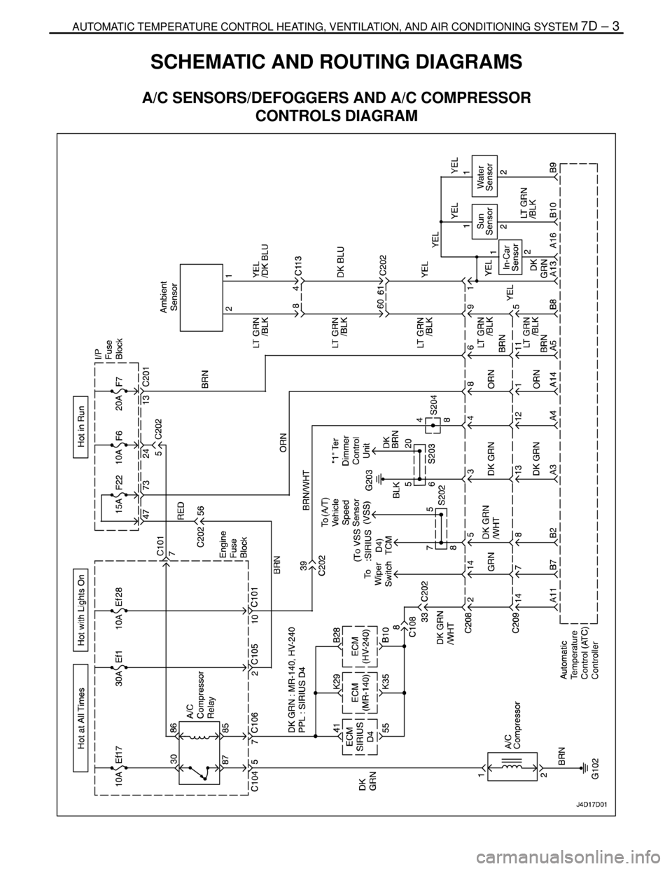
SCHEMATIC AND ROUTING DIAGRAMS7D–3 . . . . .
A/C Sensors/Defoggers and A/C Compressor
Controls Diagram 7D–3. . . . . . . . . . . . . . . . . . . . . . . .
A/C Blower and Motor Controls Diagram 7D–4. . . . . .
DIAGNOSIS7D–5 . . . . . . . . . . . . . . . . . . . . . . . . . . . . . . . .
GENERAL A/C DIAGNOSTICS 7D–5. . . . . . . . . . . . . . .
V5 SYSTEM AIR CONDITIONING AND AUTOMATIC
TEMPERATURE CONTROL (ATC) 7D–5. . . . . . . . . .
Self–Diagnostic Circuit Check 7D–5. . . . . . . . . . . . . . .
Automatic Temperature Controller Does Not
Operate When Ignition Is ON 7D–6. . . . . . . . . . . . . .
Controller Does Not Illuminate When Light Switch
Is ON 7D–7. . . . . . . . . . . . . . . . . . . . . . . . . . . . . . . . . .
No Hot Air From Blower 7D–8. . . . . . . . . . . . . . . . . . . .
No Cool Air From Blower 7D–10. . . . . . . . . . . . . . . . . .
Blower Motor Does Not Run At All 7D–12. . . . . . . . . .
Mode Control Do Not Work 7D–14. . . . . . . . . . . . . . . .
Air Source Selection Not Controlled 7D–16. . . . . . . . .
Compressor Magnetic Clutch Does Not
Engage 7D–17. . . . . . . . . . . . . . . . . . . . . . . . . . . . . . . .
DIAGNOSTIC TROUBLE CODES 7D–18. . . . . . . . . . . .
Code 1 – In–Car Sensor Error 7D–18. . . . . . . . . . . . .
Code 2 – Ambient Air Temperature Sensor
Error 7D–20. . . . . . . . . . . . . . . . . . . . . . . . . . . . . . . . . .
Code 3 – Water Sensor Error 7D–22. . . . . . . . . . . . . . .
Code 4 – Air Mix Door Error 7D–24. . . . . . . . . . . . . . . . Code 5 – Sun Sensor Error 7D–27. . . . . . . . . . . . . . . .
Code 6 – Power Transistor Error 7D–29. . . . . . . . . . . .
Code 7 – Max–Hi Relay Error 7D–31. . . . . . . . . . . . . .
MAINTENANCE AND REPAIR7D–32 . . . . . . . . . . . . . .
ON–VEHICLE SERVICE 7D–32. . . . . . . . . . . . . . . . . . . .
GENERAL A/C SYSTEM SERVICE
PROCEURES 7D–32. . . . . . . . . . . . . . . . . . . . . . . . . . . .
General Service Procedures 7D–32. . . . . . . . . . . . . . .
SERVICEABLE COMPONENTS 7D–33. . . . . . . . . . . . .
Common HVAC Components 7D–33. . . . . . . . . . . . . . .
Automatic Temperature Control Assembly 7D–33. . . .
Inlet Air Door Motor 7D–34. . . . . . . . . . . . . . . . . . . . . . .
Mode Door Motor 7D–35. . . . . . . . . . . . . . . . . . . . . . . . .
Air Mix Door Motor 7D–35. . . . . . . . . . . . . . . . . . . . . . . .
Water Sensor 7D–36. . . . . . . . . . . . . . . . . . . . . . . . . . . .
Ambient Air Temperature Sensor 7D–36. . . . . . . . . . .
In–Car Temperature Sensor 7D–37. . . . . . . . . . . . . . . .
Sun Sensor 7D–37. . . . . . . . . . . . . . . . . . . . . . . . . . . . . .
UNIT REPAIR 7D–39. . . . . . . . . . . . . . . . . . . . . . . . . . . . .
V5 AIR CONDITIONING COMPRESSOR
OVERHAUL 7D–39. . . . . . . . . . . . . . . . . . . . . . . . . . . . .
Compressor Overhaul 7D–39. . . . . . . . . . . . . . . . . . . . .
GENERAL DESCRIPTION AND SYSTEM
OPERATION7D–40 . . . . . . . . . . . . . . . . . . . . . . . . . . . . .
GENERAL INFORMATION 7D–40. . . . . . . . . . . . . . . . . .
The V5 System 7D–40. . . . . . . . . . . . . . . . . . . . . . . . . . .
System Components – Control 7D–40. . . . . . . . . . . . .
Page 2058 of 2643
AUTOMATIC TEMPERATURE CONTROL HEATING, VENTILATION, AND AIR CONDITIONING SYSTEM 7D – 3
DAEWOO V–121 BL4
SCHEMATIC AND ROUTING DIAGRAMS
A/C SENSORS/DEFOGGERS AND A/C COMPRESSOR
CONTROLS DIAGRAM
Page 2059 of 2643
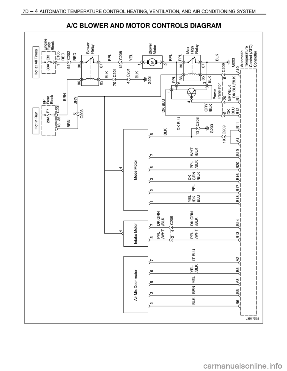
7D – 4IAUTOMATIC TEMPERATURE CONTROL HEATING, VENTILATION, AND AIR CONDITIONING SYSTEM
DAEWOO V–121 BL4
A/C BLOWER AND MOTOR CONTROLS DIAGRAM