Page 74 of 2643
1.4L/1.6L DOHC ENGINE MECHANICAL 1C1 – 31
DAEWOO V–121 BL4
TIMING BELT CHECK AND ADJUST
Tools Required
J–42492 Timing Belt Adjuster
KM–470–B Angular Torque Gauge
Adjustment Procedure
1. Disconnect the negative battery cable.
2. Remove the air cleaner outlet hose from the throttle
body.
3. Remove the breather tube from the camshaft cover.
4. Remove the air cleaner housing bolts.
5. Remove the air cleaner housing.
6. Remove the right front wheel. Refer to Section 2E,
Tires and Wheels.
7. Remove the right front wheel well splash shield.
8. Remove the serpentine accessory drive belt. Refer
to Section 6B, Power Steering Pump.
9. Remove the crankshaft pulley bolt.
10. Remove the crankshaft pulley.
11. Remove the upper front timing belt cover bolts.
12. Remove the upper front timing belt cover.
13. Remove the lower front timing belt cover bolts.
14. Remove the lower front timing belt cover.
15. Install the crankshaft pulley bolt.
Page 75 of 2643
1C1 – 32I1.4L/1.6L DOHC ENGINE MECHANICAL
DAEWOO V–121 BL4
16. Rotate the crankshaft at least one full turn clock-
wise using the crankshaft pulley bolt.
17. Align the mark on the crankshaft gear with the
notch at the bottom of the rear timing belt cover.
18. Align the camshaft gear timing marks.
19. Slightly loosen the water pump retaining bolts.
20. Rotate the water pump clockwise using the timing
belt adjuster J–42492.
21. Rotate the water pump clockwise until the adjust
arm pointer of the timing belt automatic tensioner is
aligned with the notch in the timing belt automatic
tensioner bracket.
22. Tighten the water pump retaining bolts.
23. Rotate the crankshaft two full turns clockwise using
the crankshaft pulley.
24. Loosen the water pump retaining bolts.
Page 77 of 2643
1C1 – 34I1.4L/1.6L DOHC ENGINE MECHANICAL
DAEWOO V–121 BL4
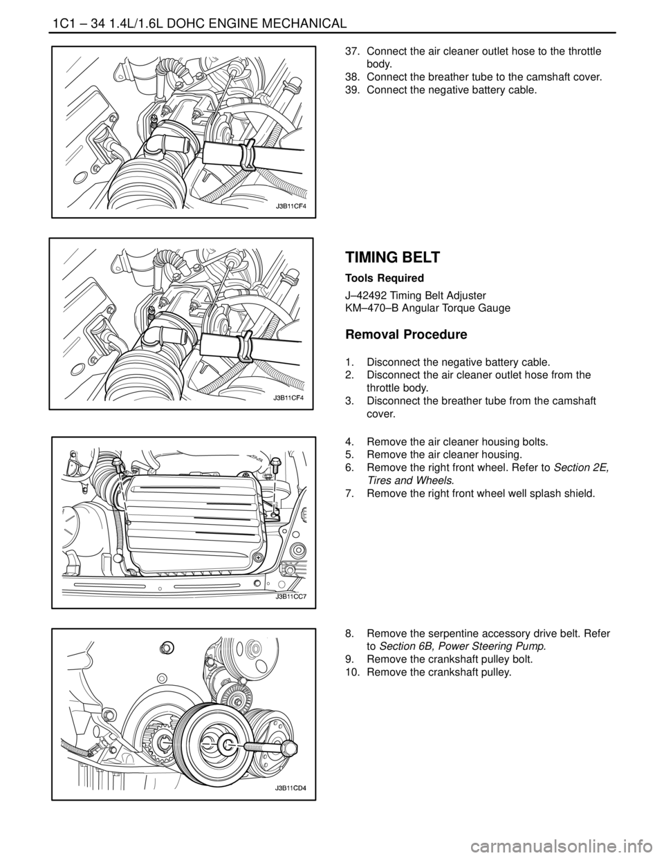
37. Connect the air cleaner outlet hose to the throttle
body.
38. Connect the breather tube to the camshaft cover.
39. Connect the negative battery cable.
TIMING BELT
Tools Required
J–42492 Timing Belt Adjuster
KM–470–B Angular Torque Gauge
Removal Procedure
1. Disconnect the negative battery cable.
2. Disconnect the air cleaner outlet hose from the
throttle body.
3. Disconnect the breather tube from the camshaft
cover.
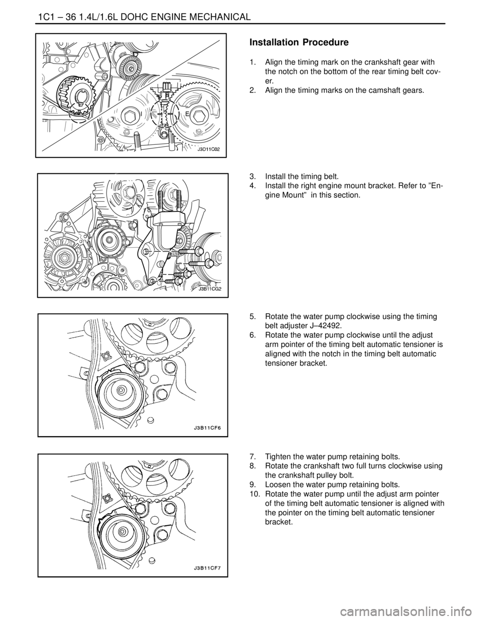
4. Remove the air cleaner housing bolts.
5. Remove the air cleaner housing.
6. Remove the right front wheel. Refer to Section 2E,
Tires and Wheels.
7. Remove the right front wheel well splash shield.
8. Remove the serpentine accessory drive belt. Refer
to Section 6B, Power Steering Pump.
9. Remove the crankshaft pulley bolt.
10. Remove the crankshaft pulley.
Page 79 of 2643
1C1 – 36I1.4L/1.6L DOHC ENGINE MECHANICAL
DAEWOO V–121 BL4
Installation Procedure
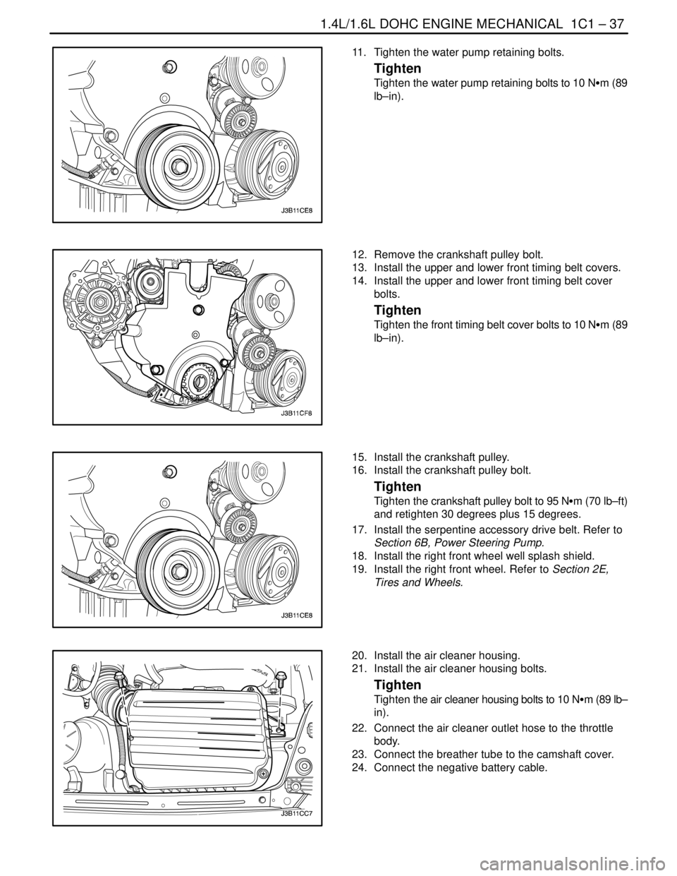
1. Align the timing mark on the crankshaft gear with
the notch on the bottom of the rear timing belt cov-
er.
2. Align the timing marks on the camshaft gears.
3. Install the timing belt.
4. Install the right engine mount bracket. Refer to ”En-
gine Mount” in this section.
5. Rotate the water pump clockwise using the timing
belt adjuster J–42492.
6. Rotate the water pump clockwise until the adjust
arm pointer of the timing belt automatic tensioner is
aligned with the notch in the timing belt automatic
tensioner bracket.
7. Tighten the water pump retaining bolts.
8. Rotate the crankshaft two full turns clockwise using
the crankshaft pulley bolt.
9. Loosen the water pump retaining bolts.
10. Rotate the water pump until the adjust arm pointer
of the timing belt automatic tensioner is aligned with
the pointer on the timing belt automatic tensioner
bracket.
Page 80 of 2643
1.4L/1.6L DOHC ENGINE MECHANICAL 1C1 – 37
DAEWOO V–121 BL4
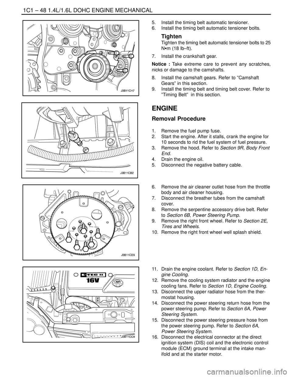
11. Tighten the water pump retaining bolts.
Tighten
Tighten the water pump retaining bolts to 10 NSm (89
lb–in).
12. Remove the crankshaft pulley bolt.
13. Install the upper and lower front timing belt covers.
14. Install the upper and lower front timing belt cover
bolts.
Tighten
Tighten the front timing belt cover bolts to 10 NSm (89
lb–in).
15. Install the crankshaft pulley.
16. Install the crankshaft pulley bolt.
Tighten
Tighten the crankshaft pulley bolt to 95 NSm (70 lb–ft)
and retighten 30 degrees plus 15 degrees.
17. Install the serpentine accessory drive belt. Refer to
Section 6B, Power Steering Pump.
18. Install the right front wheel well splash shield.
19. Install the right front wheel. Refer to Section 2E,
Tires and Wheels.
20. Install the air cleaner housing.
21. Install the air cleaner housing bolts.
Tighten
Tighten the air cleaner housing bolts to 10 NSm (89 lb–
in).
22. Connect the air cleaner outlet hose to the throttle
body.
23. Connect the breather tube to the camshaft cover.
24. Connect the negative battery cable.
Page 88 of 2643

1.4L/1.6L DOHC ENGINE MECHANICAL 1C1 – 45
DAEWOO V–121 BL4
CAMSHAFT GEARS
Removal Procedure
1. Disconnect the negative battery cable.
2. Remove the engine cover.
3. Remove the timing belt. Refer to ”Timing Belt” in
this section.
4. Disconnect the ignition wires from the spark plugs.
5. Disconnect the engine ventilation hoses from the
camshaft cover.
6. Remove the camshaft cover bolts.
7. Remove the camshaft cover and the camshaft cov-
er gasket.
Notice : Take extreme care to prevent any scratches,
nicks or damage to the camshafts.
8. While holding the intake camshaft firmly in place,
remove the intake camshaft gear bolt.
9. Remove the intake camshaft gear.
10. While holding the exhaust camshaft firmly in place,
remove the exhaust camshaft gear bolt.
11. Remove the exhaust camshaft gear.
Installation Procedure
Notice : Take extreme care to prevent any scratches,
nicks or damage to the camshafts.
1. Install the intake camshaft gear.
2. While holding the intake camshaft firmly in place,
install the intake camshaft gear bolt.
Tighten
Tighten the intake camshaft gear bolt to 67.5 NSm (49
lb–ft).
Page 89 of 2643

1C1 – 46I1.4L/1.6L DOHC ENGINE MECHANICAL
DAEWOO V–121 BL4
3. Install the exhaust camshaft gear.
4. While holding the exhaust camshaft firmly in place,
install the exhaust camshaft gear bolt.
Tighten
Tighten the exhaust camshaft gear bolt to 67.5 NSm
(49 lb–ft).
5. Apply a small amount of gasket sealant to the cor-
ners of the front camshaft caps and to the top of
the rear camshaft cover–to–cylinder head seal.
6. Install the camshaft cover and the camshaft cover
gasket.
7. Install the camshaft cover bolts.
Tighten
Tighten the camshaft cover nuts to 10 NSm (89 lb–in).
8. Connect the engine ventilation hoses to the cam-
shaft cover.
9. Connect the ignition wires to the spark plugs.
10. Install the timing belt. Refer to ”Timing Belt” in this
section.
11. Install the engine cover. Refer to ”Engine Cover” in
this section.
12. Connect the negative battery cable.
REAR TIMING BELT COVER
Removal Procedure
1. Remove the timing belt and the timing belt cover.
Refer to ”Timing Belt” in this section.
2. Remove the camshaft gears. Refer to ”Camshaft
Gears” in this section.
3. Remove the crankshaft gear.
4. Remove the timing belt automatic tensioner bolts.
5. Remove the timing belt automatic tensioner.
Page 91 of 2643
1C1 – 48I1.4L/1.6L DOHC ENGINE MECHANICAL
DAEWOO V–121 BL4
5. Install the timing belt automatic tensioner.
6. Install the timing belt automatic tensioner bolts.
Tighten
Tighten the timing belt automatic tensioner bolts to 25
NSm (18 lb–ft).
7. Install the crankshaft gear.
Notice : Take extreme care to prevent any scratches,
nicks or damage to the camshafts.
8. Install the camshaft gears. Refer to ”Camshaft
Gears” in this section.
9. Install the timing belt and timing belt cover. Refer to
”Timing Belt” in this section.
ENGINE
Removal Procedure
1. Remove the fuel pump fuse.
2. Start the engine. After it stalls, crank the engine for
10 seconds to rid the fuel system of fuel pressure.
3. Remove the hood. Refer to Section 9R, Body Front
End.
4. Drain the engine oil.
5. Disconnect the negative battery cable.
6. Remove the air cleaner outlet hose from the throttle
body and air cleaner housing.
7. Disconnect the breather tubes from the camshaft
cover.
8. Remove the serpentine accessory drive belt. Refer
to Section 6B, Power Steering Pump.
9. Remove the right front wheel. Refer to Section 2E,
Tires and Wheels.
10. Remove the right front wheel well splash shield.
11. Drain the engine coolant. Refer to Section 1D, En-
gine Cooling.
12. Remove the cooling system radiator and the engine
cooling fans. Refer to Section 1D, Engine Cooling.
13. Disconnect the upper radiator hose from the ther-
mostat housing.
14. Disconnect the power steering return hose from the
power steering pump. Refer to Section 6A, Power
Steering System.
15. Disconnect the power steering pressure hose from
the power steering pump. Refer to Section 6A,
Power Steering System.
16. Disconnect the electrical connector at the direct
ignition system (DIS) coil and the electronic control
module (ECM) ground terminal at the intake man-
ifold and at the starter motor.