Page 1539 of 2643

5A1 – 190IZF 4 HP 16 AUTOMATIC TRANSAXLE
DAEWOO V–121 BL4
MAINTENANCE AND REPAIR
ON–VEHICLE SERVICE
TRANSAXLE FLUID LEVEL
CHECKING PROCEDURE
Tools Required
DW260–070 Plug Remover/Installer
Inspection Procedure
1. Start the engine and allow the engine to idle for
approximately 5 minutes, or, if possible, drive the
vehicle for a few kilometers(miles) to warm the
transaxle fluid. Check the fluid level when the trans-
axle is over 30°C(86°F).
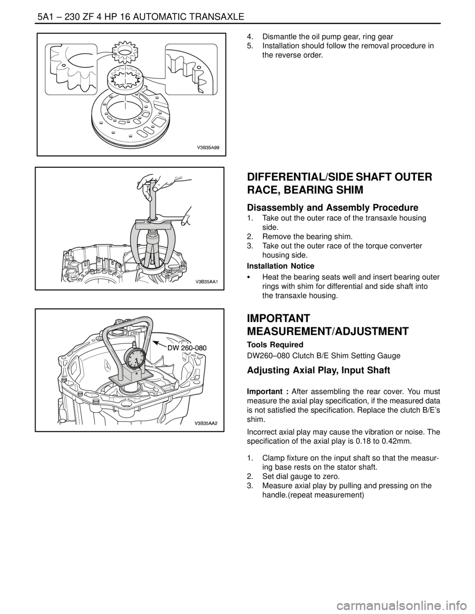
2. Press the brake pedal and move the shift lever
through the gear ranges, pausing a few seconds in
each range. Return the shift lever to the park posi-
tion. (Left–Hand Drive Shown, Right–Hand Drive
Similar.)
3. Raise and suitably support the vehicle.
4. Place a fluid container below the fluid level plug.
CAUTION : Do not remove the fluid level plug if the
transaxle fluid is hot. This may cause injury if the fluid
drains from the plug hole.
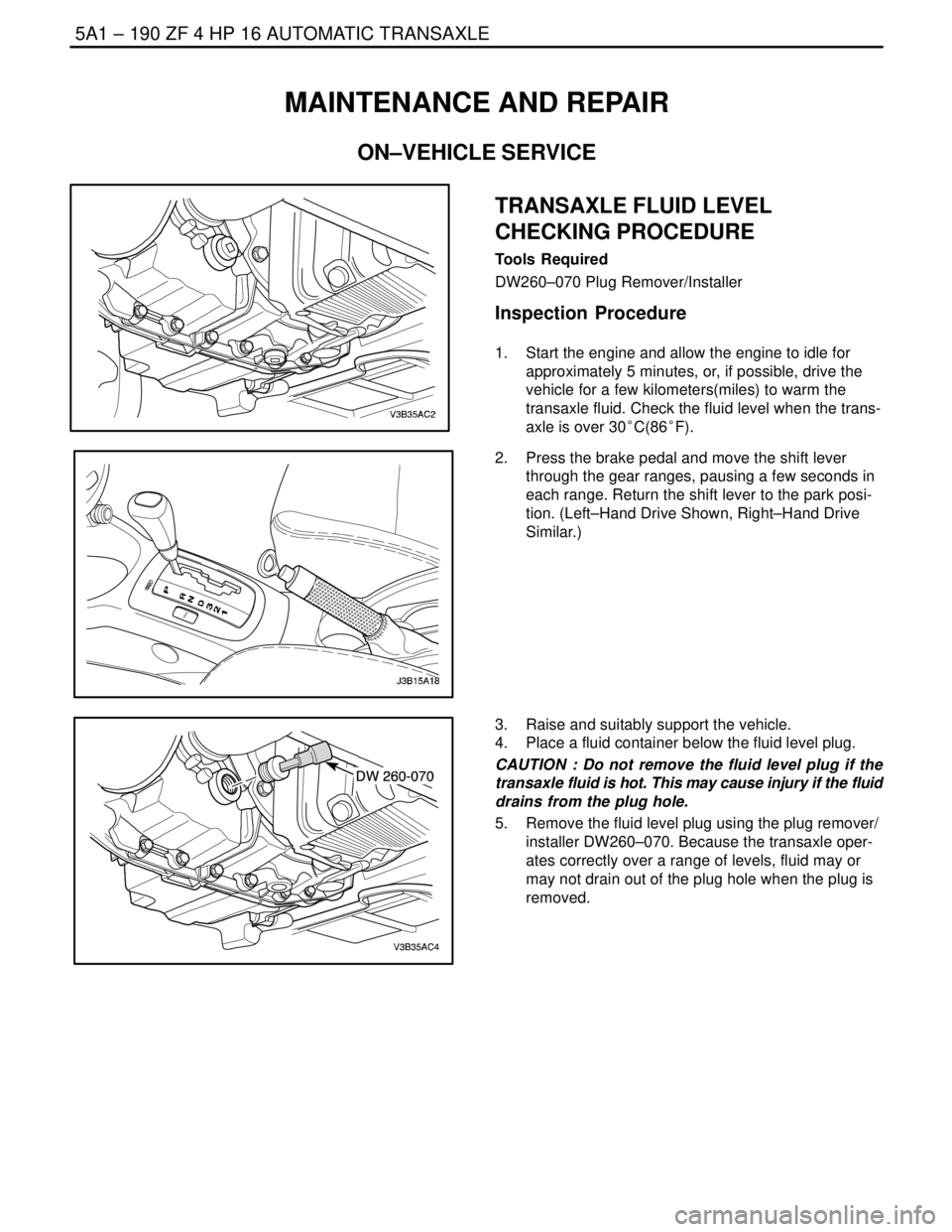
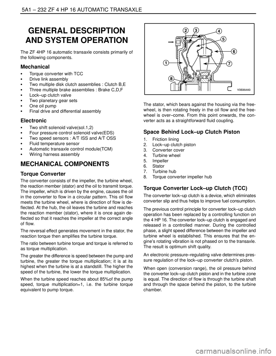
5. Remove the fluid level plug using the plug remover/
installer DW260–070. Because the transaxle oper-
ates correctly over a range of levels, fluid may or
may not drain out of the plug hole when the plug is
removed.
Page 1569 of 2643
5A1 – 220IZF 4 HP 16 AUTOMATIC TRANSAXLE
DAEWOO V–121 BL4
PLANETARY GEAR SET
Disassembly and Assembly Procedure
1. Remove the clutch B/E. Refer to ”Clutch B/E” in
this section.
2. Remove the rear sun gear.
3. Remove the planetary gear set.
4. Remove snap ring from front ring gear.
5. Take out rear planetary gear set.
Page 1570 of 2643
ZF 4 HP 16 AUTOMATIC TRANSAXLE 5A1 – 221
DAEWOO V–121 BL4
6. Remove the axial needle bearing.
7. Take out front gear set with rear ring gear, front sun
gear and oil trays.
8. Take oil trays and front sun gear off the planetary
gear set.
9. Installation should follow the removal procedure in
the reverse order.
BRAKE C/D
Tools Required
DW260–160 Brake C/D Snap Ring Remover/Installer
Disassembly and Assembly Procedure
1. Take snap ring out of transaxle housing.
Page 1575 of 2643
5A1 – 226IZF 4 HP 16 AUTOMATIC TRANSAXLE
DAEWOO V–121 BL4
5. Release the piston F by applying compressed air to
the bore.
6. Remove piston F and bearing plate with spur gear.
7. Installation should follow the removal procedure in
the reverse order.
Removal Notice
Since the bearing set is tight, press the bearing plate up-
ward from underneath to remove it.
ORIGIN
ON/OFF– 12.54
+ / –
ORIGIN
ON/OFF– 12.54
+ / –
Tools Required
DW 260–110 Brake F Disc Clearance Measuring Bar
Measuring Installation Space F
1. Using a depth gauge, measuring from the transaxle
housing sealing surfaces to the piston’s disc sup-
port surface at two opposing points = M1, M2
2. Average the measurement values M1, M2 = BF
S CALCULATION
BF = (M1+M2)/2
S CALCULATION
M1 = 18.6mm
M2 = 18.8mm
BF = 18.7mm
Determining Adjusting Disc F
1. Calculate the test dimension PF (PF = BF – MF)
BF = installation space
MF = disc set thickness (assume 14.50mm)
S EXAMPLE
BF = 18.70mm
MF = 14.50mm
PE = 4.2mm
Page 1578 of 2643
ZF 4 HP 16 AUTOMATIC TRANSAXLE 5A1 – 229
DAEWOO V–121 BL4
PARKING LOCK SYSTEM
Disassembly and Assembly Procedure
1. Remove the parking lock assembly.
S Parking lock system is consist of parking pawl,
leg spring, support bolt.
2. Installation should follow the removal procedure in
the reverse order.
BEARING PLATE(WITH SPUR GEAR)
ASSEMBLY
Disassembly and Assembly Procedure
1. Remove the piston F. Refer to ”Brake F” in this
section.
2. Remove the bearing plate bolts and bearing plate.
3. Installation should follow the removal procedure in
the reverse order.
Installation Notice
Tighten
Tighten the bearing plate bolts to 27 NSm (17 lb–ft).
OIL PUMP ASSEMBLY
Disassembly and Assembly Procedure
1. Remove the oil pump housing bolts.
2. Using the plastic hammer. Take out the oil pump
housing.
Installation Notice
Tighten
Tighten the oil pump housing bolts 10 NSm (89 lb–in).
3. Remove the stator shaft bolts.
Page 1579 of 2643

5A1 – 230IZF 4 HP 16 AUTOMATIC TRANSAXLE
DAEWOO V–121 BL4
4. Dismantle the oil pump gear, ring gear
5. Installation should follow the removal procedure in
the reverse order.
DIFFERENTIAL/SIDE SHAFT OUTER
RACE, BEARING SHIM
Disassembly and Assembly Procedure
1. Take out the outer race of the transaxle housing
side.
2. Remove the bearing shim.
3. Take out the outer race of the torque converter
housing side.
Installation Notice
S Heat the bearing seats well and insert bearing outer
rings with shim for differential and side shaft into
the transaxle housing.
IMPORTANT
MEASUREMENT/ADJUSTMENT
Tools Required
DW260–080 Clutch B/E Shim Setting Gauge
Adjusting Axial Play, Input Shaft
Important : After assembling the rear cover. You must
measure the axial play specification, if the measured data
is not satisfied the specification. Replace the clutch B/E’s
shim.
Incorrect axial play may cause the vibration or noise. The
specification of the axial play is 0.18 to 0.42mm.
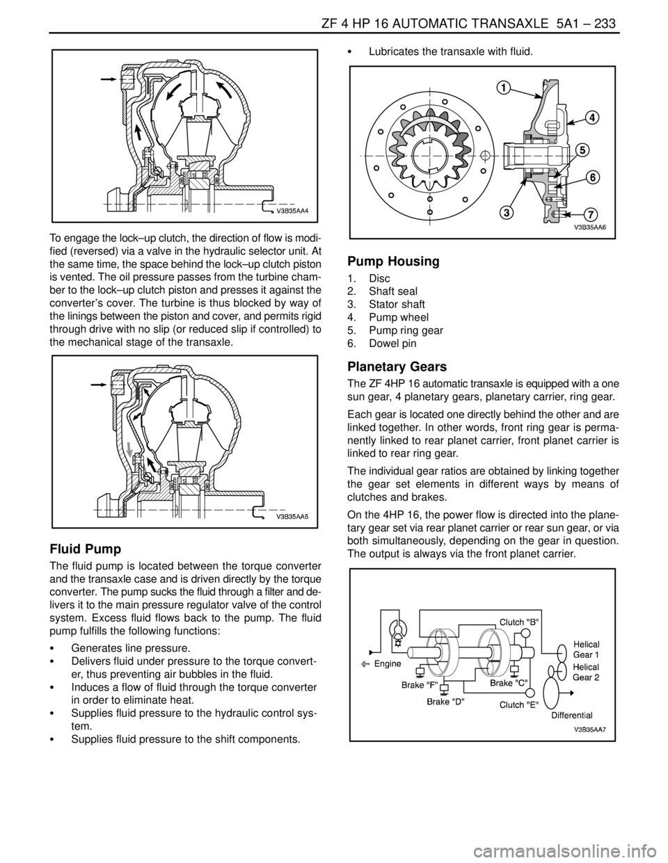
1. Clamp fixture on the input shaft so that the measur-
ing base rests on the stator shaft.
2. Set dial gauge to zero.
3. Measure axial play by pulling and pressing on the
handle.(repeat measurement)
Page 1581 of 2643

5A1 – 232IZF 4 HP 16 AUTOMATIC TRANSAXLE
DAEWOO V–121 BL4
GENERAL DESCRIPTION
AND SYSTEM OPERATION
The ZF 4HP 16 automatic transaxle consists primarily of
the following components.
Mechanical
S Torque converter with TCC
S Drive link assembly
S Two multiple disk clutch assemblies : Clutch B,E
S Three multiple brake assemblies : Brake C,D,F
S Lock–up clutch valve
S Two planetary gear sets
S One oil pump
S Final drive and differential assembly
Electronic
S Two shift solenoid valve(sol.1,2)
S Four pressure control solenoid valve(EDS)
S Two speed sensors : A/T ISS and A/T OSS
S Fluid temperature sensor
S Automatic transaxle control module(TCM)
S Wiring harness assembly
MECHANICAL COMPONENTS
Torque Converter
The converter consists of the impeller, the turbine wheel,
the reaction member (stator) and the oil to transmit torque.
The impeller, which is driven by the engine, causes the oil
in the converter to flow in a circular pattern. This oil flow
meets the turbine wheel, where is direction of flow is de-
flected. At the hub, the oil leaves the turbine and reaches
the reaction member (stator), where it is once again de-
flected so that it reaches the impeller at the correct angle
of flow.
The reversal effect generates movement in the stator, the
reaction torque then amplifies the turbine torque.
The ratio between turbine torque and torque is referred to
as torque multiplication.
The greater the difference is speed between the pump and
turbine, the greater the torque multiplication; it is at its
highest when the turbine is at a standstill. The higher the
speed of the turbine, the lower the torque multiplication.
When the turbine speed reaches about 85%of the pump
speed, torque multiplication=1, i.e. the turbine torque
equivalent to pump torque.
The stator, which bears against the housing via the free-
wheel, is then rotating freely in the oil flow and the free-
wheel is over–come. From this point onwards, the con-
verter acts as a straightforward fluid coupling.
Space Behind Lock–up Clutch Piston
1. Friction lining
2. Lock–up clutch piston
3. Converter cover
4. Turbine wheel
5. Impeller
6. Stator
7. Turbine hub
8. Torque converter impeller hub
Torque Converter Lock–up Clutch (TCC)
The converter lock–up clutch is a device, which eliminates
converter slip and thus helps to improve fuel consumption.
The previous control principle for converter lock–up clutch
operation has been replaced by a controlling function on
the 4 HP 16. The converter lock–up clutch is engaged and
released in a controlled manner. During the controlled
phase, a slight speed difference between the impeller and
turbine wheel is established. This ensures that the en-
gine’s rotating vibration is not phased on to the transaxle.
The result is optimum shift quality.
An electronic pressure–regulating valve determines pres-
sure regulation of the lock–up converter clutch’s piston.
When open (conversion range), the oil pressure behind
the converter lock–up clutch piston and in the turbine zone
is equal. The direction of flow is through the turbine shaft
and through the space behind the piston, to the turbine
chamber.
Page 1582 of 2643

ZF 4 HP 16 AUTOMATIC TRANSAXLE 5A1 – 233
DAEWOO V–121 BL4
To engage the lock–up clutch, the direction of flow is modi-
fied (reversed) via a valve in the hydraulic selector unit. At
the same time, the space behind the lock–up clutch piston
is vented. The oil pressure passes from the turbine cham-
ber to the lock–up clutch piston and presses it against the
converter’s cover. The turbine is thus blocked by way of
the linings between the piston and cover, and permits rigid
through drive with no slip (or reduced slip if controlled) to
the mechanical stage of the transaxle.
Fluid Pump
The fluid pump is located between the torque converter
and the transaxle case and is driven directly by the torque
converter. The pump sucks the fluid through a filter and de-
livers it to the main pressure regulator valve of the control
system. Excess fluid flows back to the pump. The fluid
pump fulfills the following functions:
S Generates line pressure.
S Delivers fluid under pressure to the torque convert-
er, thus preventing air bubbles in the fluid.
S Induces a flow of fluid through the torque converter
in order to eliminate heat.
S Supplies fluid pressure to the hydraulic control sys-
tem.
S Supplies fluid pressure to the shift components.S Lubricates the transaxle with fluid.
Pump Housing
1. Disc
2. Shaft seal
3. Stator shaft
4. Pump wheel
5. Pump ring gear
6. Dowel pin
Planetary Gears
The ZF 4HP 16 automatic transaxle is equipped with a one
sun gear, 4 planetary gears, planetary carrier, ring gear.
Each gear is located one directly behind the other and are
linked together. In other words, front ring gear is perma-
nently linked to rear planet carrier, front planet carrier is
linked to rear ring gear.
The individual gear ratios are obtained by linking together
the gear set elements in different ways by means of
clutches and brakes.
On the 4HP 16, the power flow is directed into the plane-
tary gear set via rear planet carrier or rear sun gear, or via
both simultaneously, depending on the gear in question.
The output is always via the front planet carrier.