Page 1133 of 2643

4F – 52IANTILOCK BRAKE SYSTEM
DAEWOO V–121 BL4
StepNo Yes Value(s) Action
9Check the continuity of the wiring in both front wheel
speed sensor circuits between the ABS connector
and the wheel speed sensor wheel speed sensor
connector on each side of the vehicle.
1. The left side uses terminals 6 and 7 at the ABS
connector.
2. The right side uses terminals 4 and 5 at the
ABS connector.
Is continuity good for both harnesses?–Go to Step 11Go to Step 10
10Repair the discontinuity found in the front wheel
speed sensor harness.
Is the repair complete?–System OK–
111. Visually inspect the wiring for the rear wheel
speed sensors.
2. Check that the wheel speed sensors are prop-
erly mounted and that the retaining bolts are
properly tightened.
Is there any damage?–Go to Step 12Go to Step 13
12Repair or replace components as required.
Is the repair complete?–System OK–
13Remove each wheel speed sensor from the rear
knuckles and inspect the toothed ring through the
wheel speed sensor mounting holes.
1. Check for any damaged or missing teeth.
2. Check that the ring is properly positioned under
the wheel speed sensor.
Is there any damage or other fault with either speed
ring?–Go to Step 14Go to Step 15
14Replace the rear wheel hub with the proper unit.
Is the repair complete?–System OK–
151. Disconnect the rear wheel speed sensor har-
nesses from the wheel speed sensor connec-
tors.
2. Measure the wheel speed sensor resistance at
the wheel speed sensor connector terminals.
Does the resistance fall within the specified values
for both wheel speed sensors?1280–1920 WGo to Step 17Go to Step 16
16Replace the faulty wheel speed sensor.
Is the repair complete?–System OK–
171. The ABS control module connector should still
be disconnected. Disconnect it now if it is not.
2. Check each wheel speed sensor harness for a
short circuit between its wires with a digital
ohmmeter attached to the two terminals at the
harness side of the wheel speed sensor con-
nector.
3. Also check each wheel speed sensor harness
wire for a short to ground from the connector
terminals.
Is there any short circuit in either wheel speed sen-
sor harness?–Go to Step 18Go to Step 19
Page 1134 of 2643
ANTILOCK BRAKE SYSTEM 4F – 53
DAEWOO V–121 BL4
StepNo Yes Value(s) Action
18Repair the short circuit in the wiring or from a wire to
ground.
Is the repair complete?–System OK–
19Check the continuity of the wiring in both rear wheel
speed sensor circuits between the ABS connector
and the wheel speed sensor wheel speed sensor
connector on each side of the vehicle.
1. The left side uses terminals 8 and 9 at the ABS
connector.
2. The right side uses terminals 1 and 3 at the
ABS connector.
Is continuity good for both harnesses?–Go to Step 21Go to Step 20
20Repair the discontinuity found in the rear wheel
speed sensor wheel speed sensor harness or con-
nector C110.
Is the repair complete?–System OK–
21Replace the ABS unit.
Is the repair complete?–System OK–
Page 1140 of 2643
ANTILOCK BRAKE SYSTEM 4F – 59
DAEWOO V–121 BL4
DIAGNOSTIC TROUBLE CODE (DTC) C0931
OVERHEATED
DTC Description
The brake can be overheated when the TCS controls the
brake system to reduce the velocity of driving wheel. At
this moment, the EBCM calculates the brake application
time and frequency and shows the warning sign of over
heated driving wheel to the driver.Cause(s)
S EBCM show the driving wheel temperature over
400 °C.
Fail Action
TCS dose not functioning when the DTC C0931 is de-
tected.
Page 1143 of 2643

4F – 62IANTILOCK BRAKE SYSTEM
DAEWOO V–121 BL4
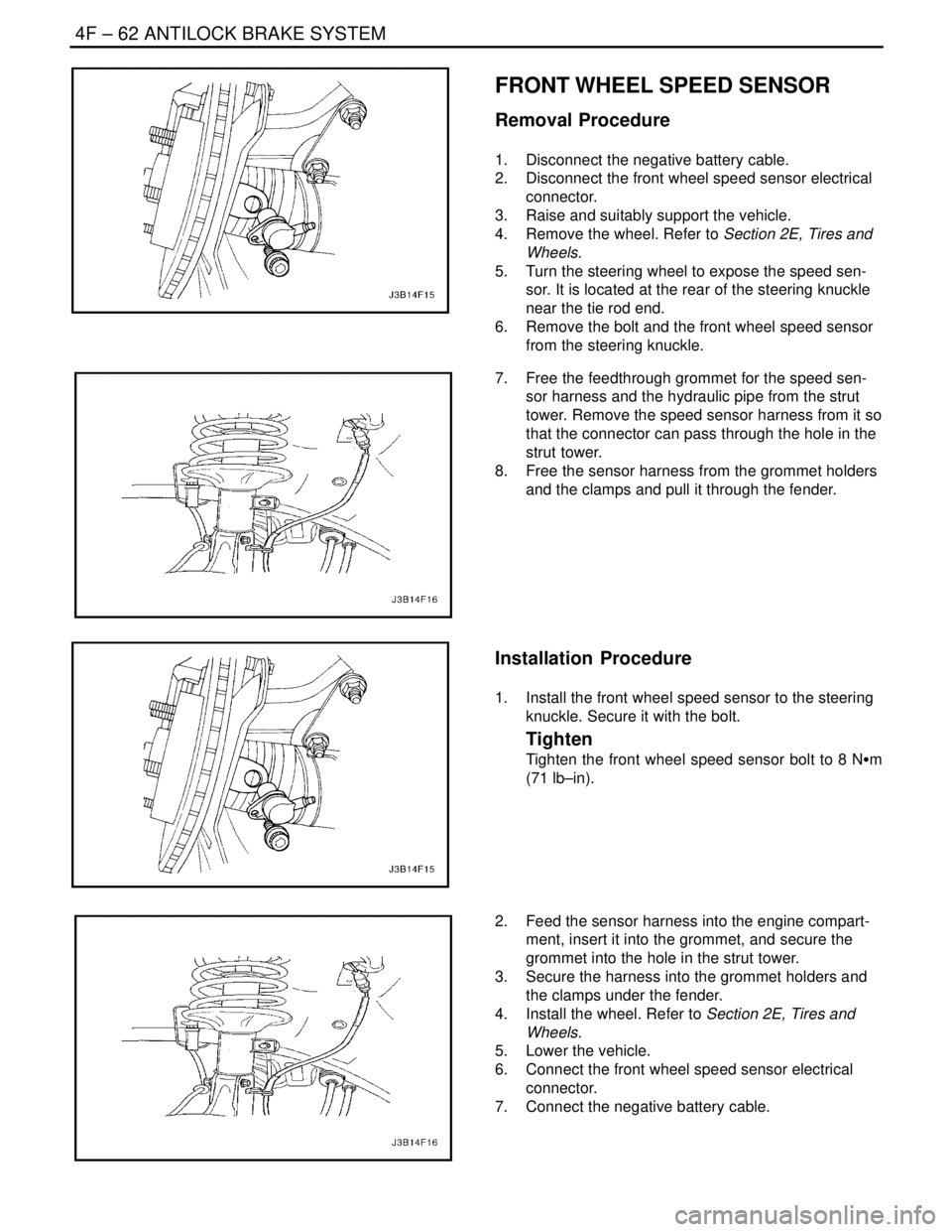
FRONT WHEEL SPEED SENSOR
Removal Procedure
1. Disconnect the negative battery cable.
2. Disconnect the front wheel speed sensor electrical
connector.
3. Raise and suitably support the vehicle.
4. Remove the wheel. Refer to Section 2E, Tires and
Wheels.
5. Turn the steering wheel to expose the speed sen-
sor. It is located at the rear of the steering knuckle
near the tie rod end.
6. Remove the bolt and the front wheel speed sensor
from the steering knuckle.
7. Free the feedthrough grommet for the speed sen-
sor harness and the hydraulic pipe from the strut
tower. Remove the speed sensor harness from it so
that the connector can pass through the hole in the
strut tower.
8. Free the sensor harness from the grommet holders
and the clamps and pull it through the fender.
Installation Procedure
1. Install the front wheel speed sensor to the steering
knuckle. Secure it with the bolt.
Tighten
Tighten the front wheel speed sensor bolt to 8 NSm
(71 lb–in).
2. Feed the sensor harness into the engine compart-
ment, insert it into the grommet, and secure the
grommet into the hole in the strut tower.
3. Secure the harness into the grommet holders and
the clamps under the fender.
4. Install the wheel. Refer to Section 2E, Tires and
Wheels.
5. Lower the vehicle.
6. Connect the front wheel speed sensor electrical
connector.
7. Connect the negative battery cable.
Page 1144 of 2643

ANTILOCK BRAKE SYSTEM 4F – 63
DAEWOO V–121 BL4
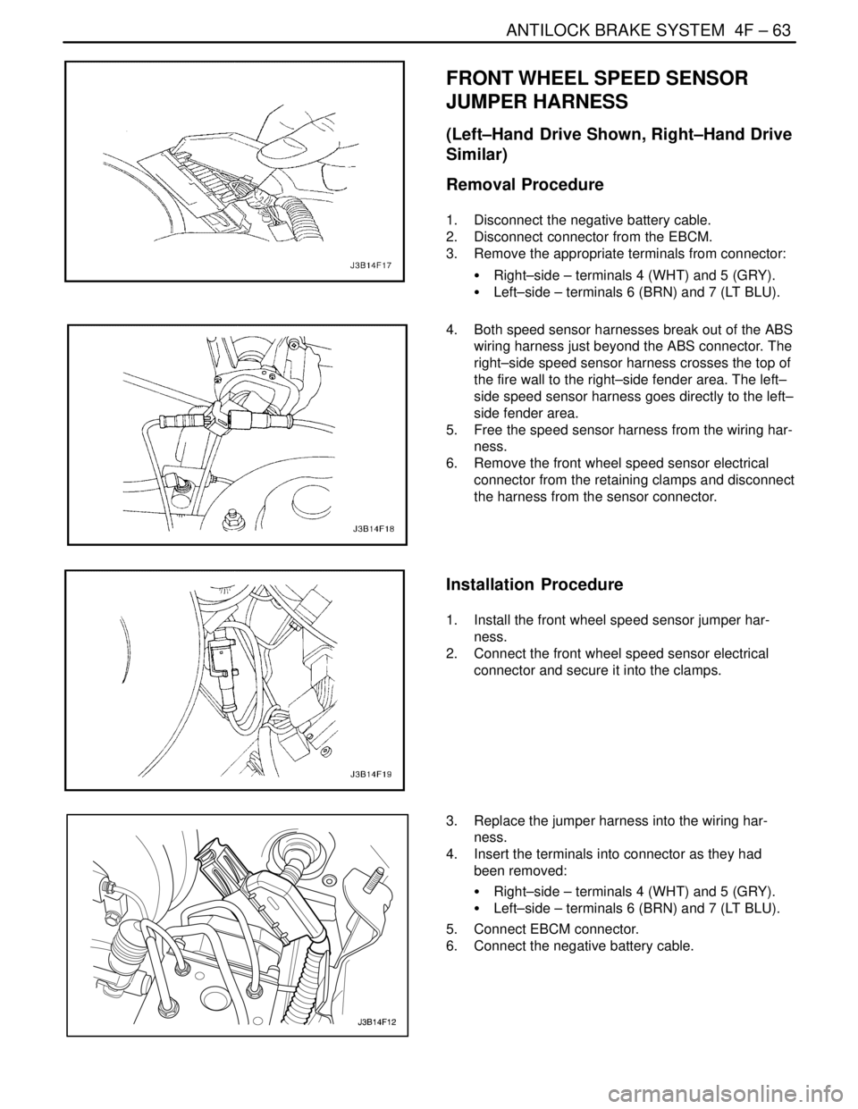
FRONT WHEEL SPEED SENSOR
JUMPER HARNESS
(Left–Hand Drive Shown, Right–Hand Drive
Similar)
Removal Procedure
1. Disconnect the negative battery cable.
2. Disconnect connector from the EBCM.
3. Remove the appropriate terminals from connector:
S Right–side – terminals 4 (WHT) and 5 (GRY).
S Left–side – terminals 6 (BRN) and 7 (LT BLU).
4. Both speed sensor harnesses break out of the ABS
wiring harness just beyond the ABS connector. The
right–side speed sensor harness crosses the top of
the fire wall to the right–side fender area. The left–
side speed sensor harness goes directly to the left–
side fender area.
5. Free the speed sensor harness from the wiring har-
ness.
6. Remove the front wheel speed sensor electrical
connector from the retaining clamps and disconnect
the harness from the sensor connector.
Installation Procedure
1. Install the front wheel speed sensor jumper har-
ness.
2. Connect the front wheel speed sensor electrical
connector and secure it into the clamps.
3. Replace the jumper harness into the wiring har-
ness.
4. Insert the terminals into connector as they had
been removed:
S Right–side – terminals 4 (WHT) and 5 (GRY).
S Left–side – terminals 6 (BRN) and 7 (LT BLU).
5. Connect EBCM connector.
6. Connect the negative battery cable.
Page 1145 of 2643
4F – 64IANTILOCK BRAKE SYSTEM
DAEWOO V–121 BL4
REAR WHEEL SPEED SENSOR
Removal Procedure
1. Disconnect the negative battery cable.
2. Raise and suitably support the vehicle.
3. Disconnect the rear wheel speed sensor electrical
connector.
4. Remove the rear hub unit from the knuckle assem-
bly, because the wheel speed sensor is not service-
able separately.
Installation Procedure
1. Install the rear hub unit to the knuckle assembly.
Tighten
Tighten the rear hub unit to the knuckle assembly to
65 NSm (48 lb–ft).
2. Connect the rear wheel speed sensor electrical
connector.
Page 1146 of 2643

ANTILOCK BRAKE SYSTEM 4F – 65
DAEWOO V–121 BL4
GENERAL DESCRIPTION AND SYSTEM
OPERATION
BASIC KNOWLEDGE REQUIRED
Before using this section, it is important that you have a ba-
sic knowledge of the following items. Without this knowl-
edge, it will be difficult to use the diagnostic procedures
contained in this section.
S Basic Electrical Circuits : You should understand
the basic theory of electricity and know the mean-
ing of voltage, current (amps), and resistance
(ohms). You should understand what happens in a
circuit with an open or shorted wire. You should be
able to read and understand a wiring diagram.
S Use of Circuit Testing Tools : You should know how
to use a test light and how to bypass components
to test circuits using fused jumper wires. You should
be familiar with a digital multimeter. You should be
able to measure voltage, resistance, and current,
and be familiar with the controls and how to use
them correctly.
ABS SYSTEM COMPONENTS
The ABS 5.3 Antilock Braking System (ABS) consists of
a conventional hydraulic brake system plus antilock com-
ponents. The conventional brake system includes a vacu-
um booster, master cylinder, front disc brakes, rear lead-
ing/trailing drum brakes, interconnecting hydraulic brake
pipes and hoses, brake fluid level sensor and the BRAKE
indicator.
The ABS components include a hydraulic unit, an elec-
tronic brake control module (EBCM), two system fuses,
four wheel speed sensors (one at each wheel), intercon-
necting wiring, the ABS indicator, the EBD indicator (which
is connected to the parking lamp) and the rear disk brakes.
See “ABS Component Locator” in this section for the gen-
eral layout of this system.
The hydraulic unit with the attached EBCM is located be-
tween the surge tank and the fire wall on the left side of the
vehicle.
The basic hydraulic unit configuration consists of hydraulic
check valves, two solenoid valves for each wheel, a hy-
draulic pump, two accumulators, and two damper. The hy-
draulic unit controls hydraulic pressure to the front calipers
and rear wheel cylinders by modulating hydraulic pressure
to prevent wheel lockup.
Nothing in the hydraulic unit or the EBCM is serviceable.
In the event of any failure, the entire ABS unit with at-
tached EBCM must be replaced. For more information, re-
fer to ”Base Braking Mode” and ”Antilock Braking Mode”
in this section.
BASE BRAKING MODE
The baseline braking mode of the ABS 5.3 system used
in this vehicle is a diagonal split system. In this system,
one master cylinder circuit supplies pressure to the right
front and the left rear brakes; the other circuit supplies
pressure to the left front and the right rear brakes. All
valves in the hydraulic modulator are in their normal, non–
energized positions as shown in the drawings found in
”ABS System Components” in this section.
Page 1147 of 2643
4F – 66IANTILOCK BRAKE SYSTEM
DAEWOO V–121 BL4
1. Check Valve
2. Inlet Valve
3. Outlet Valve
4. Pump
5. Accumulator
6. Damper7. Pump Motor
8. Hydraulic Circuit 2
9. Hydraulic Circuit 1
10. Master Cylinder
11. Master Cylinder Reservoir
ANTILOCK BRAKING MODE – APPLY
If a wheel speed sensor detects a wheel locking up, the
electronic brake control module (EBCM) closes the nor-
mally open inlet valve for the brake on that wheel to pre-
vent adding more hydraulic pressure to that brake.