2004 DAEWOO LACETTI speed
[x] Cancel search: speedPage 40 of 2643
1A – 8IGENERAL ENGINE INFORMATION
DAEWOO V–121 BL4
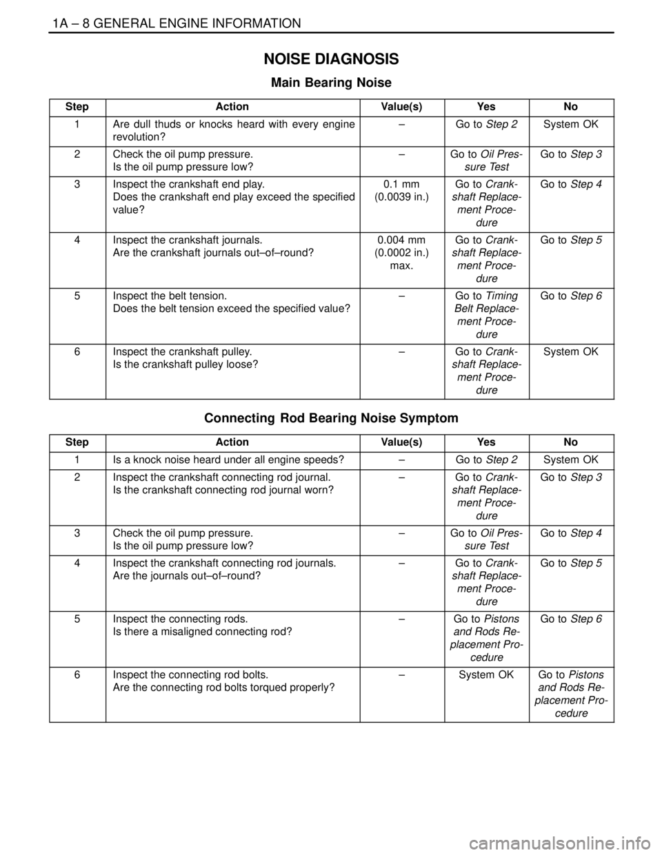
NOISE DIAGNOSIS
Main Bearing Noise
StepActionValue(s)YesNo
1Are dull thuds or knocks heard with every engine
revolution?–Go to Step 2System OK
2Check the oil pump pressure.
Is the oil pump pressure low?–Go to Oil Pres-
sure TestGo to Step 3
3Inspect the crankshaft end play.
Does the crankshaft end play exceed the specified
value?0.1 mm
(0.0039 in.)Go to Crank-
shaft Replace-
ment Proce-
dureGo to Step 4
4Inspect the crankshaft journals.
Are the crankshaft journals out–of–round?0.004 mm
(0.0002 in.)
max.Go to Crank-
shaft Replace-
ment Proce-
dureGo to Step 5
5Inspect the belt tension.
Does the belt tension exceed the specified value?–Go to Timing
Belt Replace-
ment Proce-
dureGo to Step 6
6Inspect the crankshaft pulley.
Is the crankshaft pulley loose?–Go to Crank-
shaft Replace-
ment Proce-
dureSystem OK
Connecting Rod Bearing Noise Symptom
StepActionValue(s)YesNo
1Is a knock noise heard under all engine speeds?–Go to Step 2System OK
2Inspect the crankshaft connecting rod journal.
Is the crankshaft connecting rod journal worn?–Go to Crank-
shaft Replace-
ment Proce-
dureGo to Step 3
3Check the oil pump pressure.
Is the oil pump pressure low?–Go to Oil Pres-
sure TestGo to Step 4
4Inspect the crankshaft connecting rod journals.
Are the journals out–of–round?–Go to Crank-
shaft Replace-
ment Proce-
dureGo to Step 5
5Inspect the connecting rods.
Is there a misaligned connecting rod?–Go to Pistons
and Rods Re-
placement Pro-
cedureGo to Step 6
6Inspect the connecting rod bolts.
Are the connecting rod bolts torqued properly?–System OKGo to Pistons
and Rods Re-
placement Pro-
cedure
Page 83 of 2643
1C1 – 40I1.4L/1.6L DOHC ENGINE MECHANICAL
DAEWOO V–121 BL4
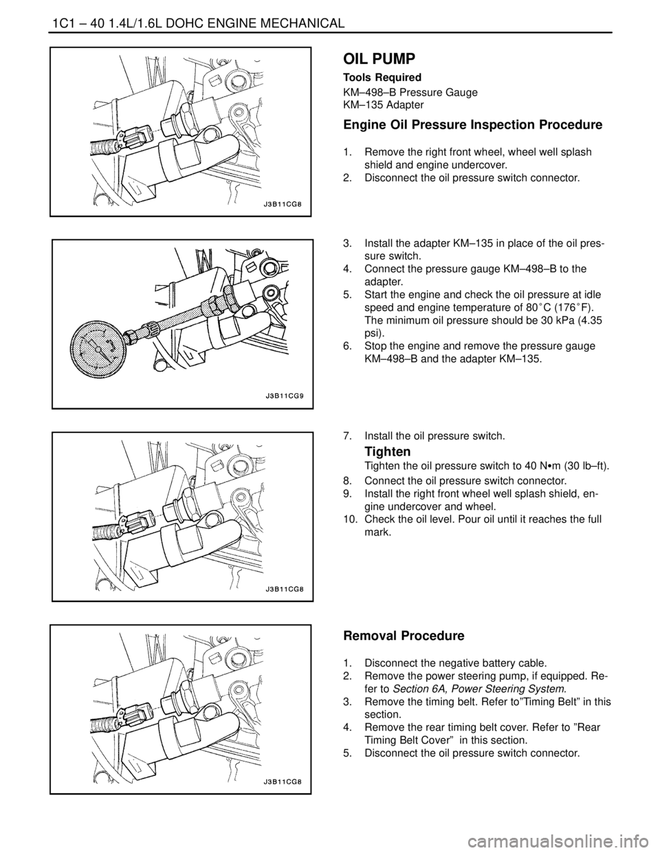
OIL PUMP
Tools Required
KM–498–B Pressure Gauge
KM–135 Adapter
Engine Oil Pressure Inspection Procedure
1. Remove the right front wheel, wheel well splash
shield and engine undercover.
2. Disconnect the oil pressure switch connector.
3. Install the adapter KM–135 in place of the oil pres-
sure switch.
4. Connect the pressure gauge KM–498–B to the
adapter.
5. Start the engine and check the oil pressure at idle
speed and engine temperature of 80°C (176°F).
The minimum oil pressure should be 30 kPa (4.35
psi).
6. Stop the engine and remove the pressure gauge
KM–498–B and the adapter KM–135.
7. Install the oil pressure switch.
Tighten
Tighten the oil pressure switch to 40 NSm (30 lb–ft).
8. Connect the oil pressure switch connector.
9. Install the right front wheel well splash shield, en-
gine undercover and wheel.
10. Check the oil level. Pour oil until it reaches the full
mark.
Removal Procedure
1. Disconnect the negative battery cable.
2. Remove the power steering pump, if equipped. Re-
fer to Section 6A, Power Steering System.
3. Remove the timing belt. Refer to”Timing Belt” in this
section.
4. Remove the rear timing belt cover. Refer to ”Rear
Timing Belt Cover” in this section.
5. Disconnect the oil pressure switch connector.
Page 120 of 2643

1.4L/1.6L DOHC ENGINE MECHANICAL 1C1 – 77
DAEWOO V–121 BL4
GENERAL DESCRIPTION
AND SYSTEM OPERATION
CYLINDER HEAD AND GASKET
The cylinder head is made of an aluminum alloy. The cylin-
der head uses cross–flow intake and exhaust ports. A
spark plug is located in the center of each combustion
chamber. The cylinder head houses the dual camshafts.
CRANKSHAFT
The crankshaft has eight integral weights which are cast
with it for balancing. Oil holes run through the center of the
crankshaft to supply oil to the connecting rods, the bear-
ings, the pistons, and the other components. The end
thrust load is taken by the thrust washers installed at the
center journal.
TIMING BELT
The timing belt coordinates the crankshaft and the dual
overhead camshafts and keeps them synchronized. The
timing belt also turns the water pump. The timing belt and
the pulleys are toothed so that there is no slippage be-
tween them. There are two idler pulleys. An automatic ten-
sioner pulley maintains the timing belt’s correct tension.
The timing belt is made of a tough reinforced rubber similar
to that used on the serpentine accessory drive belt. The
timing belt requires no lubrication.
OIL PUMP
The oil pump draws engine oil from the oil pan and feeds
it under pressure to the various parts of the engine. An oil
strainer is mounted before the inlet of the oil pump to re-
move impurities which could clog or damage the oil pump
or other engine components. When the drive gear rotates,
the driven gear rotates. This causes the space between
the gears to constantly open and narrow, pulling oil in from
the oil pan when the space opens and pumping the oil out
to the engine as it narrows.
At high engine speeds, the oil pump supplies a much high-
er amount of oil than is required for lubrication of the en-
gine. The oil pressure regulator prevents too much oil from
entering the engine lubrication passages. During normal
oil supply, a coil spring and valve keep the bypass closed,
directing all of the oil pumped to the engine. When the
amount of oil being pumped increases, the pressure be-
comes high enough to overcome the force of the spring.This opens the valve of the oil pressure regulator, allowing
the excess oil to flow through the valve and drain back to
the oil pan.
OIL PAN
The engine oil pan is mounted to the bottom of the cylinder
block. The engine oil pan houses the crankcase and is
made of cast metal.
Engine oil is pumped from the oil pan by the oil pump. After
it passes through the oil filter, it is fed through two paths
to lubricate the cylinder block and the cylinder head. In one
path, the oil is pumped through the oil passages in the
crankshaft to the connecting rods, then to the pistons and
the cylinders. It then drains back to the oil pan. In the sec-
ond path, the oil is pumped through the oil passages to the
camshaft. The oil passes through the internal passage-
ways in the camshafts to lubricate the valve assemblies
before draining back to the oil pan.
EXHAUST MANIFOLD
A single four–port, rear–takedown manifold is used with
this engine. The manifold is designed to direct escaping
exhaust gases out of the combustion chambers with a
minimum of back pressure. The oxygen sensor is
mounted to the exhaust manifold.
INTAKE MANIFOLD
The intake manifold has four independent long ports and
uses inertial supercharging to improve engine torque at
low and moderate speeds. The plenum is attached to the
intake manifold.
CAMSHAFTS
This engine is a dual overhead camshaft (DOHC) type,
which means there are two camshafts. One camshaft op-
erates the intake valves, and the other camshaft operates
the exhaust valves. The camshafts sit in journals on the
top of the engine in the cylinder head and are held in place
by camshaft caps. The camshaft journals of the cylinder
head are drilled to create oil passages. Engine oil travels
to the camshafts under pressure where it lubricates each
camshaft journal. The oil returns to the oil pan through
drain holes in the cylinder head. The camshaft lobes are
machined into the solid camshaft to open and close the in-
take and the exhaust valves precisely the correct amount
at the correct time. The camshaft lobes are oiled by splash
action from pressurized oil escaping from the camshaft
journals.
Page 154 of 2643
1C2 – 34I1.8L DOHC ENGINE MECHANICAL
DAEWOO V–121 BL4
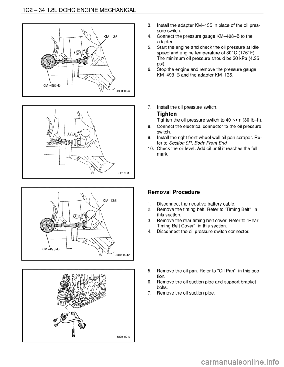
3. Install the adapter KM–135 in place of the oil pres-
sure switch.
4. Connect the pressure gauge KM–498–B to the
adapter.
5. Start the engine and check the oil pressure at idle
speed and engine temperature of 80°C (176°F).
The minimum oil pressure should be 30 kPa (4.35
psi).
6. Stop the engine and remove the pressure gauge
KM–498–B and the adapter KM–135.
7. Install the oil pressure switch.
Tighten
Tighten the oil pressure switch to 40 NSm (30 lb–ft).
8. Connect the electrical connector to the oil pressure
switch.
9. Install the right front wheel well oil pan scraper. Re-
fer to Section 9R, Body Front End.
10. Check the oil level. Add oil until it reaches the full
mark.
Removal Procedure
1. Disconnect the negative battery cable.
2. Remove the timing belt. Refer to ”Timing Belt” in
this section.
3. Remove the rear timing belt cover. Refer to ”Rear
Timing Belt Cover” in this section.
4. Disconnect the oil pressure switch connector.
5. Remove the oil pan. Refer to ”Oil Pan” in this sec-
tion.
6. Remove the oil suction pipe and support bracket
bolts.
7. Remove the oil suction pipe.
Page 168 of 2643

1C2 – 48I1.8L DOHC ENGINE MECHANICAL
DAEWOO V–121 BL4
40. Remove the crankshaft pulley bolts.
41. Remove the crankshaft pulley.
42. Disconnect the vacuum lines at the charcoal canis-
ter purge solenoid.
43. Disconnect the electrical connector at the charcoal
canister purge (CCP) and the exhaust gas recir-
culation (EGR) solenoid.
44. Disconnect the electrical connector at the oil pres-
sure switch.
45. Disconnect the crankshaft position sensor (CPS)
connector.
46. Disconnect the knock sensor connector.
47. Remove the transaxle torque converter bolts, if au-
tomatic transaxle equipped.
48. Remove the transaxle bell housing bolts and the oil
pan flange bolts.
49. Support the transaxle with a floor jack.
50. Install the engine lifting device.
51. Disconnect the right engine mount bracket from the
engine mount by removing the retaining bolt.
52. Remove the right engine mount bracket from the
engine block and frame mount. Refer to Section
5B, Five Speed Manual Transaxle, or Section 5A,
Automatic Transaxle.
53. Separate the engine block from the transaxle. Re-
move the engine.
Installation Procedure
1. Install the engine into the engine compartment.
2. Align the engine alignment pins to the transaxle.
3. Install the transaxle bell housing bolts.
Tighten
Tighten the transaxle bell housing bolts to 75 NSm (55
lb–ft).
4. Install the oil pan flange–to–transaxle bolts.
Tighten
Tighten the oil pan flange–to–transaxle bolts to 40
NSm (30 lb–ft).
Page 195 of 2643

1.8L DOHC ENGINE MECHANICAL 1C2 – 75
DAEWOO V–121 BL4
GENERAL DESCRIPTION
AND SYSTEM OPERATION
CYLINDER HEAD AND GASKET
The cylinder head is made of an aluminum alloy. The cylin-
der head uses cross–flow intake and exhaust ports. A
spark plug is located in the center of each combustion
chamber. The cylinder head houses the dual camshafts.
CRANKSHAFT
The crankshaft has eight integral weights which are cast
with it for balancing. Oil holes run through the center of the
crankshaft to supply oil to the connecting rods, the bear-
ings, the pistons, and the other components. The end
thrust load is taken by the thrust washers installed at the
center journal.
TIMING BELT
The timing belt coordinates the crankshaft and the dual
overhead camshafts and keeps them synchronized. The
timing belt also turns the coolant pump. The timing belt
and the pulleys are toothed so that there is no slippage be-
tween them. There are two idler pulleys. An automatic ten-
sioner pulley maintains the timing belt’s correct tension.
The timing belt is made of a tough reinforced rubber similar
to that used on the serpentine drive belt. The timing belt
requires no lubrication.
OIL PUMP
The oil pump draws engine oil from the oil pan and feeds
it under pressure to the various parts of the engine. An oil
strainer is mounted before the inlet of the oil pump to re-
move impurities which could clog or damage the oil pump
or other engine components. When the crankshaft ro-
tates, the oil pump driven gear rotates. This causes the
space between the gears to constantly open and narrow,
pulling oil in from the oil pan when the space opens and
pumping the oil out to the engine as it narrows.
At high engine speeds, the oil pump supplies a much high-
er amount of oil than required for lubrication of the engine.
The oil pressure regulator prevents too much oil from en-
tering the engine lubrication passages. During normal oil
supply, a coil spring and valve keep the bypass closed, di-
recting all of the oil pumped to the engine. When the
amount of oil being pumped increases, the pressure be-
comes high enough to overcome the force of the spring.This opens the valve of the oil pressure regulator, allowing
the excess oil to flow through the valve and drain back to
the oil pan.
OIL PAN
The engine oil pan is mounted to the bottom of the cylinder
block. The engine oil pan houses the crankcase and is
made of cast aluminum.
Engine oil is pumped from the oil pan by the oil pump. After
it passes through the oil filter, it is fed through two paths
to lubricate the cylinder block and cylinder head. In one
path, the oil is pumped through oil passages in the crank-
shaft to the connecting rods, then to the pistons and cylin-
ders. It then drains back to the oil pan. In the second path,
the oil is pumped through passages to the camshaft. The
oil passes through the internal passageways in the cam-
shafts to lubricate the valve assemblies before draining
back to the oil pan.
EXHAUST MANIFOLD
A single four–port, rear–takedown manifold is used with
this engine. The manifold is designed to direct escaping
exhaust gases out of the combustion chambers with a
minimum of back pressure. The oxygen sensor is
mounted to the exhaust manifold.
INTAKE MANIFOLD
The intake manifold has four independent long ports and
utilizes an inertial supercharging effect to improve engine
torque at low and moderate speeds.
CAMSHAFTS
This engine is a dual overhead camshaft (DOHC) type,
which means there are two camshafts. One camshaft op-
erates the intake valves, and the other camshaft operates
the exhaust valves. The camshafts sit in journals on the
top of the engine (in the cylinder head) and are held in
place by camshaft caps. The camshaft journals of the cyl-
inder head are drilled for oil passages. Engine oil travels
to the camshafts under pressure where it lubricates each
camshaft journal. The oil returns to the oil pan through
drain holes in the cylinder head. The camshaft lobes are
machined into the solid camshaft to precisely open and
close the intake and the exhaust valves the correct
amount at the correct time. The camshaft lobes are oiled
by splash action from pressurized oil escaping from the
camshaft journals.
Page 214 of 2643
ENGINE COOLING 1D – 19
DAEWOO V–121 BL4
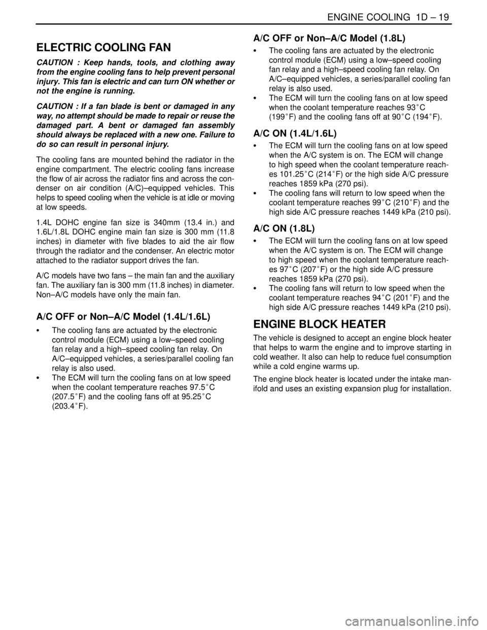
ELECTRIC COOLING FAN
CAUTION : Keep hands, tools, and clothing away
from the engine cooling fans to help prevent personal
injury. This fan is electric and can turn ON whether or
not the engine is running.
CAUTION : If a fan blade is bent or damaged in any
way, no attempt should be made to repair or reuse the
damaged part. A bent or damaged fan assembly
should always be replaced with a new one. Failure to
do so can result in personal injury.
The cooling fans are mounted behind the radiator in the
engine compartment. The electric cooling fans increase
the flow of air across the radiator fins and across the con-
denser on air condition (A/C)–equipped vehicles. This
helps to speed cooling when the vehicle is at idle or moving
at low speeds.
1.4L DOHC engine fan size is 340mm (13.4 in.) and
1.6L/1.8L DOHC engine main fan size is 300 mm (11.8
inches) in diameter with five blades to aid the air flow
through the radiator and the condenser. An electric motor
attached to the radiator support drives the fan.
A/C models have two fans – the main fan and the auxiliary
fan. The auxiliary fan is 300 mm (11.8 inches) in diameter.
Non–A/C models have only the main fan.
A/C OFF or Non–A/C Model (1.4L/1.6L)
S The cooling fans are actuated by the electronic
control module (ECM) using a low–speed cooling
fan relay and a high–speed cooling fan relay. On
A/C–equipped vehicles, a series/parallel cooling fan
relay is also used.
S The ECM will turn the cooling fans on at low speed
when the coolant temperature reaches 97.5°C
(207.5°F) and the cooling fans off at 95.25°C
(203.4°F).
A/C OFF or Non–A/C Model (1.8L)
S The cooling fans are actuated by the electronic
control module (ECM) using a low–speed cooling
fan relay and a high–speed cooling fan relay. On
A/C–equipped vehicles, a series/parallel cooling fan
relay is also used.
S The ECM will turn the cooling fans on at low speed
when the coolant temperature reaches 93°C
(199°F) and the cooling fans off at 90°C (194°F).
A/C ON (1.4L/1.6L)
S The ECM will turn the cooling fans on at low speed
when the A/C system is on. The ECM will change
to high speed when the coolant temperature reach-
es 101.25°C (214°F) or the high side A/C pressure
reaches 1859 kPa (270 psi).
S The cooling fans will return to low speed when the
coolant temperature reaches 99°C (210°F) and the
high side A/C pressure reaches 1449 kPa (210 psi).
A/C ON (1.8L)
S The ECM will turn the cooling fans on at low speed
when the A/C system is on. The ECM will change
to high speed when the coolant temperature reach-
es 97°C (207°F) or the high side A/C pressure
reaches 1859 kPa (270 psi).
S The cooling fans will return to low speed when the
coolant temperature reaches 94°C (201°F) and the
high side A/C pressure reaches 1449 kPa (210 psi).
ENGINE BLOCK HEATER
The vehicle is designed to accept an engine block heater
that helps to warm the engine and to improve starting in
cold weather. It also can help to reduce fuel consumption
while a cold engine warms up.
The engine block heater is located under the intake man-
ifold and uses an existing expansion plug for installation.
Page 216 of 2643
1E – 2IENGINE ELECTRICAL
DAEWOO V–121 BL4
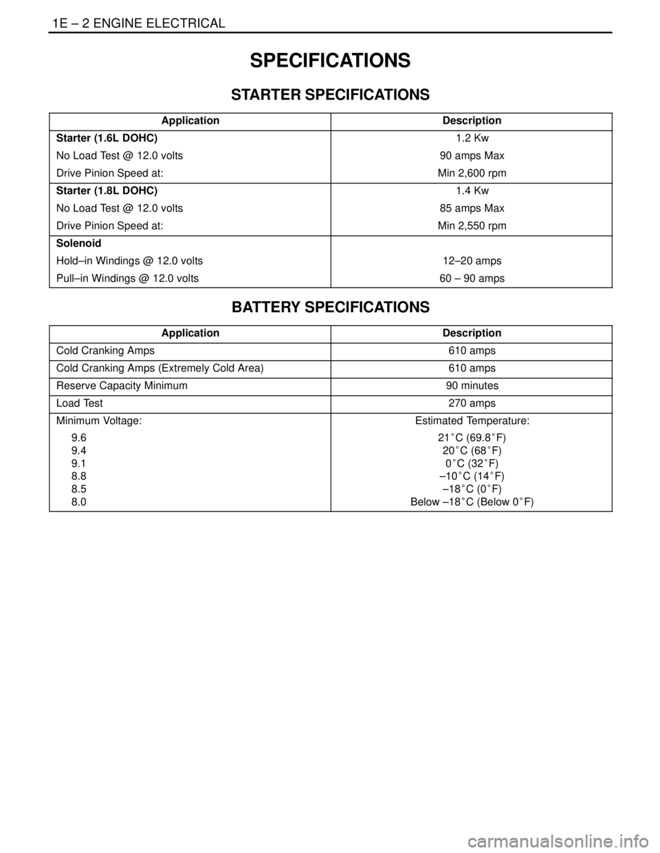
SPECIFICATIONS
STARTER SPECIFICATIONS
ApplicationDescription
Starter (1.6L DOHC)1.2 Kw
No Load Test @ 12.0 volts90 amps Max
Drive Pinion Speed at:Min 2,600 rpm
Starter (1.8L DOHC)1.4 Kw
No Load Test @ 12.0 volts85 amps Max
Drive Pinion Speed at:Min 2,550 rpm
Solenoid
Hold–in Windings @ 12.0 volts12–20 amps
Pull–in Windings @ 12.0 volts60 – 90 amps
BATTERY SPECIFICATIONS
ApplicationDescription
Cold Cranking Amps610 amps
Cold Cranking Amps (Extremely Cold Area)610 amps
Reserve Capacity Minimum90 minutes
Load Test270 amps
Minimum Voltage:
9.6
9.4
9.1
8.8
8.5
8.0Estimated Temperature:
21°C (69.8°F)
20°C (68°F)
0°C (32°F)
–10°C (14°F)
–18°C (0°F)
Below –18°C (Below 0°F)