2004 DAEWOO LACETTI car key
[x] Cancel search: car keyPage 1389 of 2643

5A1 – 40IZF 4 HP 16 AUTOMATIC TRANSAXLE
DAEWOO V–121 BL4
1. Inner Disc Carrier F
2. Clutch Plate F
3. Line Clutch Disc F
4. Clutch Outer Disc F
5. Spring Disc
6. Stop Ring
7. Cup Spring
8. O–ring
9. O–ring
10. Piston D
11. Slotted Nut
12. Roller Bearing
13. Adjust Ring
14. Bearing Plate
15. Roller Bearing
16. Spur Gear
17. Piston D
18. Spring Disc
19. Snap Ring
20. Clutch Plate D
21. Cup Spring
22. Line Clutch Disc D
23. Spring Disc
24. Disc Carrier C/D
25. Pitting Key
26. Line Clutch Disc C
27. Clutch Outer Disc C
28. Cup Spring
29. Line Clutch Disc C
30. Snap Ring
31. Piston C
32. Cylinder C
33. Snap Ring
34. Front Ring Gear
35. Oil Tray
36. Front Planetary Gear
37. Front Sun Gear
38. Snap Ring
39. Needle Bearing40. Rear Planetary Gear Set
41. Snap Ring
42. Rear Sun Gear
43. Needle Bearing
44. Snap Ring
45. Piston B
46. Clutch Plate B
47. Clutch Outer Disc B
48. Line Clutch Disc B
49. Spring Disc
50. Piston Ring
51. Inner Disc Carrier E
52. Needle Bearing
53. Snap Ring
54. Clutch Plate Disc E
55. Line Clutch Disc E
56. Clutch Outer Disc E
57. Spring Disc
58. Retainer Ring
59. O–ring
60. Oil Dam
61. Cup Spring
62. O–ring
63. Piston E
64. O–ring
65. Input Shaft
66. O–ring
67. O–ring
68. Piston
69. Oil Dam
70. O–ring
71. Cup Spring
72. Stop Ring
73. Shim
74. Needle Bearing
75. O–ring
76. Piston Ring
77. Rear Cover
Page 1398 of 2643
ZF 4 HP 16 AUTOMATIC TRANSAXLE 5A1 – 49
DAEWOO V–121 BL4
Functional Check Procedure
Inspect
1. Install a tachometer or scan tool.
2. Operate the vehicle unit proper operating tempera-
ture is reached.
3. Drive the vehicle at 80 to 88km/h (50 to 55 mph)
with light throttle(road load).
4. Maintaining throttle position, lightly touch the brake
pedal and check for release of the TCC and a slight
increase in engine speed(rpm).
5. Release the brake slowly accelerate and check for
a reapply of the Lock up clutch and a slight de-
crease in engine speed(rpm).
Torque Converter Evaluation
Torque Converter Stator
The torque converter stator roller clutch can have one of
two different type malfunctions :
A. Stator assembly freewheels in both directions.
B. Stator assembly remains Locked up at all times.
Condition A – Poor Acceleration Low
Speed
The car tends to have poor acceleration from a stand still.
At speeds above 50 to 55km/h(30 to 35mph), the car may
act normal. If poor acceleration is noted, it should first be
determined that the exhaust system is not blocked, and
the transaxle is in 1st(First) gear when starting out.
If the engine freely accelerates to high rpm in N(Neutral),
it can be assumed that the engine and exhaust system are
normal. Checking for poor performance in ”Drive” and ”Re-
verse” will help determine if the stator is freewheeling at all
times.
Condition B – Poor Acceleration High
Speed
Engine rpm and car speed limited or restricted at high
speeds. Performance when accelerating from a standstill
is normal. Engine may overheat. Visual examination of the
converter may reveal a blue color from overheating.
If the converter has been removed, the stator roller clutch
can be checked by inserting two fingers into the splined in-
ner race of the roller clutch and trying to turn freely clock-
wise, but not turn or be very difficult to turn counter clock-
wise.
Noise
Torque converter whine is usually noticed when the ve-
hicle is stopped and the transaxle is in ”Drive” or ”Re-
verse”. The noise will increase when engine rpm is in-
creased. The noise will stop when the vehicle is moving or
when the torque converter clutch is applied because both
halves of the converter are turning at the same speed.
Perform a stall test to make sure the noise is actually com-
ing from the converter :1. Place foot on brake.
2. Put gear selector in ”Drive”.
3. Depress accelerator to approximately 1200rpm for
no more than six seconds.
Notice : If the accelerator is depressed for more than six
seconds, damage to the transaxle may occur.
A torque converter noise will increase under this load.
Important : This noise should not be confused with pump
whine noise which is usually noticeable in P (Park), N
(Neutral) and all other gear ranges. Pump whine will vary
with pressure ranges.
The torque converter should be replaced under any of the
following conditions:
S External leaks in the hub weld area.
S Converter hub is scored or damaged.
S Converter pilot is broken, damaged or fits poorly
into crankshaft.
S Steel particles are found after flushing the cooler
and cooler lines.
S Pump is damaged or steel particles are found in the
converter.
S Vehicle has TCC shudder and/or no TCC apply.
Replace only after all hydraulic and electrical diag-
noses have been made.(Lock up clutch material
may be glazed.)
S Converter has an imbalance which cannot be cor–
rected. (Refer To Converter Vibration Test Proce-
dure.)
S Converter is contaminated with engine coolant con-
taining antifreeze.
S Internal failure of stator roller clutch.
S Excess end play.
S Heavy clutch debris due to overheating (blue con-
verter).
S Steel particles or clutch lining material found in fluid
filter or on magnet when no internal parts in unit are
worn or damaged(indicates that lining material
came from converter).
The torque converter should not be replace if :
S The oil has an odor, is discolored, and there is no
evidence of metal or clutch facing particles.
S The threads in one or more of the converter bolt
holes are damaged.
–correct with thread insert.
S Transaxle failure did not display evidence of dam-
age or worn internal parts, steel particles or clutch
plate lining material in unit and inside the fluid filter.
S Vehicle has been exposed to high mileage(only).
The exception may be where the Lock up clutch
damper plate lining has seen excess wear by ve-
hicles operated in heavy and/or constant traffic,
such as taxi, delivery or police use.
Lock–Up Clutch Shudder Diagnosis
The key to diagnosing lock–up clutch(TCC) shudder is to
note when it happens and under what conditions.
Page 1974 of 2643
6E – 20ISTEERING WHEEL AND COLUMN
DAEWOO V–121 BL4
GENERAL DESCRIPTION
AND SYSTEM OPERATION
STEERING WHEEL AND COLUMN
CAUTION : To ensure the energy–absorbing action of
the steering column, it is important to use only the
specified screws, bolts, and nuts, tightened to the
specified torque.
In addition to the steering function, the steering column
provides safety and security.
The energy–absorbing column is designed to compress in
a front–end collision to lessen the chance of driver injury.
The ignition switch and the lock are mounted on the col-
umn, allowing the ignition and steering operations to be
locked to inhibit theft of the car.
The column levers trigger the turn signals, the headlight
beams, and the windshield washer and wipers.The tilt steering column uses telescopic function to allow
the steering wheel to tilt up and down in and out. This en-
ables the driver to adjust the steering wheel to a comfort-
able position.
Notice : Apply a thin coat of lithium grease to all friction
points when reassembling.
The column may be disassembled and reassembled easi-
ly.IGNITION KEY REMINDER
The ignition key reminder alerts the driver that the key is
still in the ignition when the driver attempts to exit the ve-
hicle.
An internal switch in the ignition lock cylinder supplies bat-
tery voltage to the reminder chime module when all of the
following conditions are true:
S The key is in the ignition switch.
S The ignition is OFF.
S The driver’s door is open.
For information on removal and installation of the reminder
chime module, refer to Section 9E, Instrumentation/Driver
Information.
Page 2112 of 2643

8B – 8ISUPPLEMENTAL INFLATABLE RESTRAINTS (SIR)
DAEWOO V–121 BL4
SIR DIAGNOSTIC SYSTEM CHECK
Notice : If the vehicle interior has been exposed to exten-
sive water intrusion such as water leaks, driving through
high water, flooding, or other causes, the sensing and
diagnostic module(SDM) and SDM connector may need
to be replaced. With ignition OFF, inspect the area around
the SDM, including the carpet. If any significant soaking or
evidence of previous soaking is detected, the water must
be removed, water damage repaired, and the SDM and
the SDM connector must be replaced. Before attempting
any of these repairs, the supplemental inflatable re-
straints(SIR) must be disabled. Refer to ”Disabling the
SIR” and ”Sensing and Diagnostic Module(SDM)” in this
section for instructions on how to disable the SIR and re-
place the SDM.
The SIR Diagnostic System Check must always be the
starting point for any SIR diagnosis. The Diagnostic Sys-
tem Check reveals diagnostic trouble codes(DTCs)
through the use of scan tool. The diagnostic procedures
used in this section are designed to find any repair SIR
conditions. To get the best results, it is important to use the
diagnostic charts and follow the sequence listed below.
1. Perform the SIR Diagnostic System Check, which
reveal diagnostic trouble codes(DTCs) through theuse of scan tool.. It also checks for proper airbag
indicator operation.
2. Refer to the proper diagnostic chart as directed by
SIR Diagnostic System Check. Bypassing these
procedures may result in extended diagnostic time,
incorrect diagnosis, and incorrect parts replace-
ment.
3. Repeat the SIR Diagnostic System Check after any
repair or diagnostic procedures have been per-
formed to ensure that the repair has been made
correctly and that no other malfunction exists.
Circiut Description
When the ignition switch is first turned to ON, ignition volt-
age is supplied from airbag fuse to find the SDM at input
terminal A1. The SDM responds by flashing the airbag in-
dicator seven times and then turning it off while the SDM
performs tests on the SIR.
Diagnostic Aids
The order in which DTCs are diagnosed is very important.
Failure to diagnose the DTCs in the order specified may
result in extended diagnostic time, incorrect diagnosis,
and incorrect parts replacement.
SIR Diagnostic System Check
CAUTION : The sensing and the diagnosis module
(SDM) can maintain surfficient voltage to deploy the
airbags and pretensioners for 1 minute after the igni-
tion is OFF and the fuse has been removed. If the air-
bags and pretensioners are not disconnected, do not
begin service until one minute has been passed after
disconnecting power to the SDM. Otherwise, injury
could result.
CAUTION : During service procedure, be very careful
when handling the SDM. Never strike or jar the SDM.Never power the supplemental inflatable re-
straints(SIR) when the SDM is not rigidly attached to
the vehicle. All SDM mounting bolts must be carefully
tightened , and the arrow on the SDM must be point
toward the front of the vehicle to ensure proper op-
eration of the SIR. The SDM could be activated if it is
powered when it is not rigidly attached to the vehicle,
resulting in unexpected deployment and possible in-
jury.
Step
ActionValue(s)YesNo
11. Turn the ignition switch ON.
2. Observe the airbag indicator as the ignition is
being turned ON. Does the indicator flash
seven times?–System OKGo to Step 2
21. Turn the ignition to LOCK and remove the key.
2. Connect the scan tool to the data link connec-
tor(DLC). Follow the directions given in the
scan tool manual.
3. Are any DTCs displayed on the scan tool?–Go to the
DTC check
procedureGo to Step 3
3Check the fuse F1 in the interior fuse box.
Is the fuse F1 blown?–Go to Step 4Go to Step 5
4Replace the fuse F1.–––
51. Disconnect the connector C207.
2. Check the wiring shortage between the fuse F1
and the terminal 1 of the connector C207.
3. Is the wiring shorted? Then, repair the wiring.––Go to Step 6
Page 2114 of 2643

8B – 10ISUPPLEMENTAL INFLATABLE RESTRAINTS (SIR)
DAEWOO V–121 BL4
SENSING AND DIAGNOSTIC MODULE (SDM) INTEGRITY
CHECK
The following diagnostic chart must be used when all cir-
cuitry outside the sensing and diagnostic module (SDM)
has been found to operate properly, as indicated by follow-
ing the appropriate diagnostic trouble code(DTC) chart.
The chart verifies the need for SDM replacement.
Circuit Description
When the SDM recognizes ignition voltage greater than 9
volts at terminal A1 of the SDM, the airbag indicator
flashes seven times to verify operation. At this time the
SDM performs turn–on tests followed by resistance mea-surement tests and continuous monitoring tests.
When malfunction is detected, the SDM sets current DTC
and illuminates the airbag indicator.
When the malfuncation is no longer detected and/or the
ignition switch is cycled, the SDM will clear current DTCs
and move them to a history file, except for the DTCs 51
and sometimes 71. DTCs 51 will not be cleared by scan
tool because these codes require replacement of SDM.
The SDM must be replaced only after the malfunction that
set the DTC has been repaired.
Sensing and Diagnostic Module (SDM) Integrity Check
CAUTION : The sensing and diagnostic module
(SDM) can maimtain sufficient voltage to deploy the
airbags and pretensioners for 1 minute after the igni-
tion is OFF and the fuse has been removed. If the air-
bags and pretensioners are not disconnected, do not
begin service until one minute has passed after dis-
connecting the power to the SDM. Otherwise, injury
could result.
CAUTION : During service procedure, be very careful
when handling the SDM. Never strike or jar the SDM.Never power the supplemental inflatable re-
straints(SIR) when the SDM is not rigidlyattached to
the vehile. All SDM mounting bolts must be carefully
tightened , and the arrow on the SDM must be point
toward the front of the vehicle to ensure proper op-
eration of the SIR. The SDM could be activated if it is
powered when it is not rigidly attached to the vehicle,
resulting in unexpected deployment and possible in-
jury.
Step
ActionValue(s)YesNo
11. Turn the ignition to LOCK and remove the key
2. Connect all SIR components and ensure that
all the components are properly mounted.
3. Ensure that the ignition switch has been OFF
for at least 30 seconds.
4. Observe the airbag indicator as the ignition is
turned ON. Does the indicator lamp flashes
seven times ?–Clear the SIR
DTCs and
go to
”Diagnostic
System Check”Go to Step 2
21. Turn the ignition to LOCK and remove the key.
2. Connect the scan tool to DLC. Follow the direc-
tions given in the scan tool manual.
3. Turn the ignition to ON.
4. Request SIR DTC display with the scan tool. Is
the same DTC displayed that was previous oc-
curred when the SIR Diagnostic System Check
was previously performed?–Go to Step 3.Go to the table
for the DTC in-
dicated.
31. Clear SIR DTCs.
2. Turn the ignition OFF for at least 30 seconds.
3. Observe the airbag indicator as the ignition is
turned ON. Does the indicator lamp flashes
seven times ?–System OKGo to Step4
41. Turn the ignition to LOCK and remove the key.
2. Disconnect the SDM connector.
3. Replace the SDM.
4. Connect the SDM connector and ensure that
all components are properly mounted. Is the
repair complete?–Go to
”Diagnostic
System Check”–
Page 2356 of 2643
9G – 16IINTERIOR TRIM
DAEWOO V–121 BL4
GENERAL DESCRIPTION
AND SYSTEM OPERATION
INTERIOR TRIM PANELS
The interior trim panels are molded plastic and fasten with
screws or plastic clips.
PRESSURE RELIEF VENT
When all the windows are closed and the ventilation sys-
tem is on, the addition of outside air to the interior of the
vehicle causes a positive pressure within the vehicle. To
relieve the pressure, air is released through a pressure re-
lief vent. The pressure relief vents are located at the rear
quarter of the vehicle, behind the bumper fascia.
FLOOR CONSOLE
The floor console fits over the tunnel in the floor of the ve-
hicle and extends from under the center of the instrument
panel to the rear seat area. The front portion of the consolecontains the cigar lighter and the transaxle shift lever. The
rear portion of the console contains the parking brake le-
ver, a cupholder, a storage compartment, and an ashtray
for the rear seat occupants.
The sensing and diagnostic module (SDM) for the airbag
system and the remote keyless entry module are located
under the console.
FLOOR CARPET
The one–piece floor carpet goes over both the front and
the rear floor pans.
REAR COMPARTMENT SECURITY
COVER (HATCHBACK)
A rear compartment security cover is provided on the
hatchback model. The security cover is attached to the
hatch and can be easily removed if more cargo space is
needed.
Page 2499 of 2643
IMMOBILIZER ANTI–THEFT SYSTEM 9T2 – 9
DAEWOO V–121 BL4
MAINTENANCE AND REPAIR
ON–VEHICLE SERVICE
KEY CODING PROCEDURE
1. Install the immobilizer control unit cartridge in the
scan tool.
2. Turn the ignition off
3. Connect the scan tool
4. Turn the ignition on with the key to be coded
5. Enter the four–digit password that enables service
personnel to use the scan tool for key coding.
6. Use the scan tool command.
7. Verify that the key coding was successful by start-
ing the engine with each of the authorized keys.
ID CODE REPROGRAMMING
Reprogram the identification (ID) code in the following si-
tuations:
S An immobilizer control unit has been replaced.
S An electronic control module (ECM) has been re-
placed.
If a valid key has been lost, refer to ”Key Coding Proce-
dure” in this section.
TRANSPONDER
Each valid ignition key has an internal transponder which
is a read /write transponder.
The transponder contains an implementation of a crypto–
algorithm with 96 bits of user configurable secret–key con-
tained in EEPROM and transmits data to the ICU by mod-
ulating the amplitude of the electromagnetic field, and
receives data and commands in a similar way.
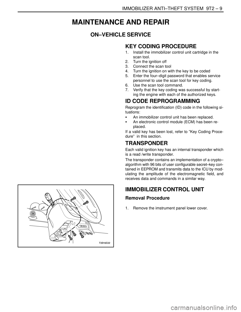
IMMOBILIZER CONTROL UNIT
Removal Procedure
1. Remove the imstrument panel lower cover.