2004 DAEWOO LACETTI Vacuum
[x] Cancel search: VacuumPage 138 of 2643
1C2 – 18I1.8L DOHC ENGINE MECHANICAL
DAEWOO V–121 BL4
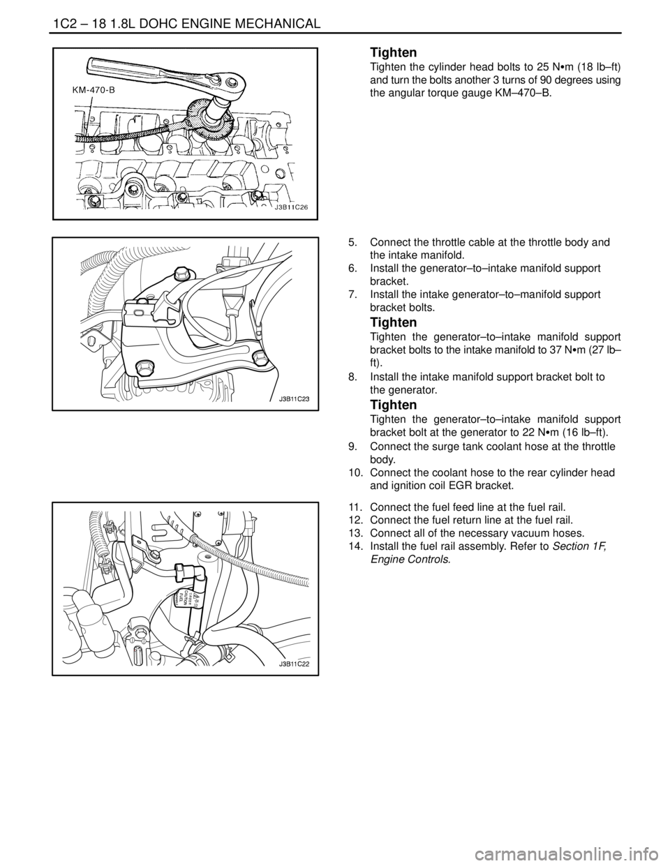
Tighten
Tighten the cylinder head bolts to 25 NSm (18 lb–ft)
and turn the bolts another 3 turns of 90 degrees using
the angular torque gauge KM–470–B.
5. Connect the throttle cable at the throttle body and
the intake manifold.
6. Install the generator–to–intake manifold support
bracket.
7. Install the intake generator–to–manifold support
bracket bolts.
Tighten
Tighten the generator–to–intake manifold support
bracket bolts to the intake manifold to 37 NSm (27 lb–
ft).
8. Install the intake manifold support bracket bolt to
the generator.
Tighten
Tighten the generator–to–intake manifold support
bracket bolt at the generator to 22 NSm (16 lb–ft).
9. Connect the surge tank coolant hose at the throttle
body.
10. Connect the coolant hose to the rear cylinder head
and ignition coil EGR bracket.
11. Connect the fuel feed line at the fuel rail.
12. Connect the fuel return line at the fuel rail.
13. Connect all of the necessary vacuum hoses.
14. Install the fuel rail assembly. Refer to Section 1F,
Engine Controls.
Page 159 of 2643
1.8L DOHC ENGINE MECHANICAL 1C2 – 39
DAEWOO V–121 BL4
8. Disconnect the idle air control (IAC) valve connec-
tor.
9. Disconnect the throttle position sensor (TPS) con-
nector.
10. Disconnect the manifold absolute pressure (MAP)
sensor connector.
11. Disconnect the coolant hoses at the throttle body.
12. Disconnect all of the necessary vacuum hoses, in-
cluding the vacuum hose at the fuel pressure regu-
lator and the brake booster vacuum hose at the
intake manifold.
13. Disconnect the throttle cable from the throttle body
and the intake manifold.
14. Remove the throttle cable bracket bolts from the
intake manifold.
15. Remove the throttle cable bracket.
16. Remove the generator–to–intake manifold strap
bracket bolts and strap.
17. Remove the fuel rail as an assembly. Refer to Sec-
tion 1F, Engine Controls.
18. Remove the generator–to–intake manifold support
bracket bolts.
19. Remove the generator–to–intake manifold support
bracket.
20. Remove the intake manifold support bracket bolt at
the engine block and the intake manifold.
21. Remove the intake manifold support bracket.
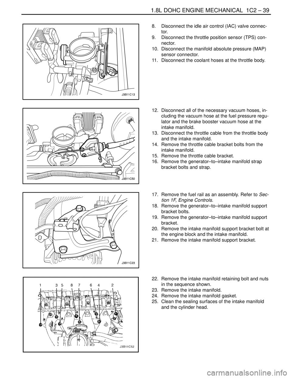
22. Remove the intake manifold retaining bolt and nuts
in the sequence shown.
23. Remove the intake manifold.
24. Remove the intake manifold gasket.
25. Clean the sealing surfaces of the intake manifold
and the cylinder head.
Page 160 of 2643
1C2 – 40I1.8L DOHC ENGINE MECHANICAL
DAEWOO V–121 BL4
Installation Procedure
1. Install the intake manifold gasket.
2. Install the intake manifold.
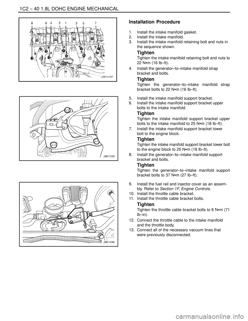
3. Install the intake manifold retaining bolt and nuts in
the sequence shown.
Tighten
Tighten the intake manifold retaining bolt and nuts to
22 NSm (16 lb–ft).
4. Install the generator–to–intake manifold strap
bracket and bolts.
Tighten
Tighten the generator–to–intake manifold strap
bracket bolts to 22 NSm (16 lb–ft).
5. Install the intake manifold support bracket.
6. Install the intake manifold support bracket upper
bolts to the intake manifold.
Tighten
Tighten the intake manifold support bracket upper
bolts to the intake manifold to 25 NSm (18 lb–ft).
7. Install the intake manifold support bracket lower
bolt to the engine block.
Tighten
Tighten the intake manifold support bracket lower bolt
to the engine block to 25 NSm (18 lb–ft).
8. Install the generator–to–intake manifold support
bracket and bolts.
Tighten
Tighten the generator–to–intake manifold support
bracket bolts to 37 NSm (27 lb–ft).
9. Install the fuel rail and injector cover as an assem-
bly. Refer to Section 1F, Engine Controls.
10. Install the throttle cable bracket.
11. Install the throttle cable bracket bolts.
Tighten
Tighten the throttle cable bracket bolts to 8 NSm (71
lb–in).
12. Connect the throttle cable to the intake manifold
and the throttle body.
13. Connect all of the necessary vacuum lines that
were previously disconnected.
Page 167 of 2643

1.8L DOHC ENGINE MECHANICAL 1C2 – 47
DAEWOO V–121 BL4
19. Disconnect the oxygen (O2) sensor connector, if
equipped.
20. Disconnect the idle air control (IAC) valve connec-
tor.
21. Disconnect the throttle position sensor (TPS) con-
nector.
22. Disconnect the engine coolant temperature sensor
(CTS) connector.
23. Disconnect the CTS connector.
24. Disconnect the generator voltage regulator connec-
tor and power lead.
25. Disconnect all of the necessary vacuum lines, in-
cluding the brake booster vacuum hose.
26. Disconnect the fuel return line at the fuel rail.
27. Disconnect the fuel feed line at the fuel rail.
28. Remove the fuel rail and injector channel cover as
an assembly. Refer to Section 1F, Engine Controls.
29. Disconnect the throttle cable from the throttle body
and the intake manifold bracket.
30. Disconnect the coolant hose at the throttle body.
31. Disconnect the heater outlet hose at the coolant
pipe.
32. Disconnect the coolant bypass hose from the cylin-
der head.
33. Disconnect the surge tank coolant hose from the
coolant pipe.
34. Disconnect the lower radiator hose from the coolant
pipe.
35. Disconnect the starter solenoid ”S” terminal wire
and power lead.
36. Remove the A/C compressor. Refer to Section 7B,
Manual Control Heating, Ventilation, and Air Condi-
tioning Systems.
37. Remove the exhaust flex pipe retaining nuts from
the exhaust manifold studs.
38. Remove the exhaust flex pipe retaining nuts from
the catalytic converter or the connecting pipe.
39. Remove the exhaust flex pipe.
Page 168 of 2643

1C2 – 48I1.8L DOHC ENGINE MECHANICAL
DAEWOO V–121 BL4
40. Remove the crankshaft pulley bolts.
41. Remove the crankshaft pulley.
42. Disconnect the vacuum lines at the charcoal canis-
ter purge solenoid.
43. Disconnect the electrical connector at the charcoal
canister purge (CCP) and the exhaust gas recir-
culation (EGR) solenoid.
44. Disconnect the electrical connector at the oil pres-
sure switch.
45. Disconnect the crankshaft position sensor (CPS)
connector.
46. Disconnect the knock sensor connector.
47. Remove the transaxle torque converter bolts, if au-
tomatic transaxle equipped.
48. Remove the transaxle bell housing bolts and the oil
pan flange bolts.
49. Support the transaxle with a floor jack.
50. Install the engine lifting device.
51. Disconnect the right engine mount bracket from the
engine mount by removing the retaining bolt.
52. Remove the right engine mount bracket from the
engine block and frame mount. Refer to Section
5B, Five Speed Manual Transaxle, or Section 5A,
Automatic Transaxle.
53. Separate the engine block from the transaxle. Re-
move the engine.
Installation Procedure
1. Install the engine into the engine compartment.
2. Align the engine alignment pins to the transaxle.
3. Install the transaxle bell housing bolts.
Tighten
Tighten the transaxle bell housing bolts to 75 NSm (55
lb–ft).
4. Install the oil pan flange–to–transaxle bolts.
Tighten
Tighten the oil pan flange–to–transaxle bolts to 40
NSm (30 lb–ft).
Page 169 of 2643
1.8L DOHC ENGINE MECHANICAL 1C2 – 49
DAEWOO V–121 BL4
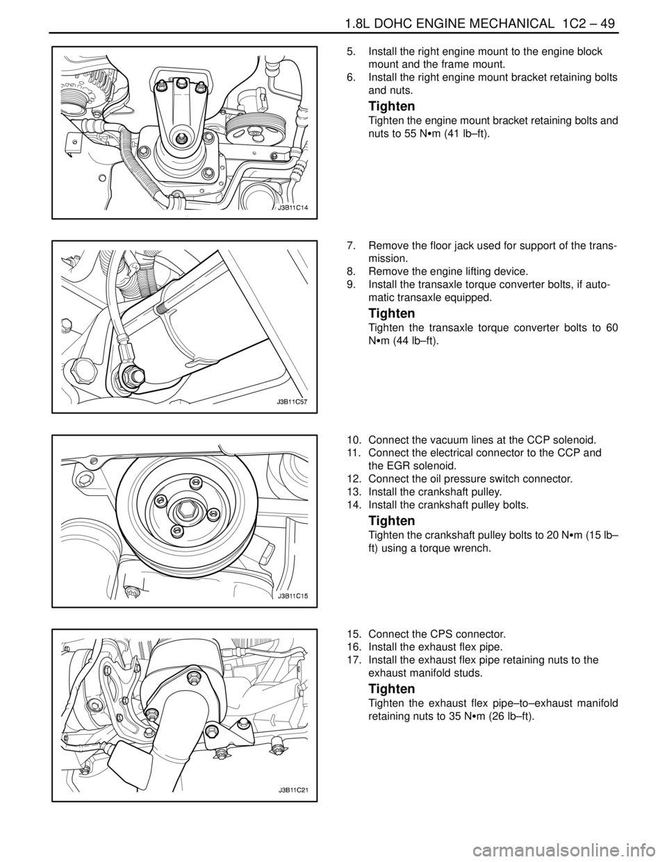
5. Install the right engine mount to the engine block
mount and the frame mount.
6. Install the right engine mount bracket retaining bolts
and nuts.
Tighten
Tighten the engine mount bracket retaining bolts and
nuts to 55 NSm (41 lb–ft).
7. Remove the floor jack used for support of the trans-
mission.
8. Remove the engine lifting device.
9. Install the transaxle torque converter bolts, if auto-
matic transaxle equipped.
Tighten
Tighten the transaxle torque converter bolts to 60
NSm (44 lb–ft).
10. Connect the vacuum lines at the CCP solenoid.
11. Connect the electrical connector to the CCP and
the EGR solenoid.
12. Connect the oil pressure switch connector.
13. Install the crankshaft pulley.
14. Install the crankshaft pulley bolts.
Tighten
Tighten the crankshaft pulley bolts to 20 NSm (15 lb–
ft) using a torque wrench.
15. Connect the CPS connector.
16. Install the exhaust flex pipe.
17. Install the exhaust flex pipe retaining nuts to the
exhaust manifold studs.
Tighten
Tighten the exhaust flex pipe–to–exhaust manifold
retaining nuts to 35 NSm (26 lb–ft).
Page 170 of 2643
1C2 – 50I1.8L DOHC ENGINE MECHANICAL
DAEWOO V–121 BL4
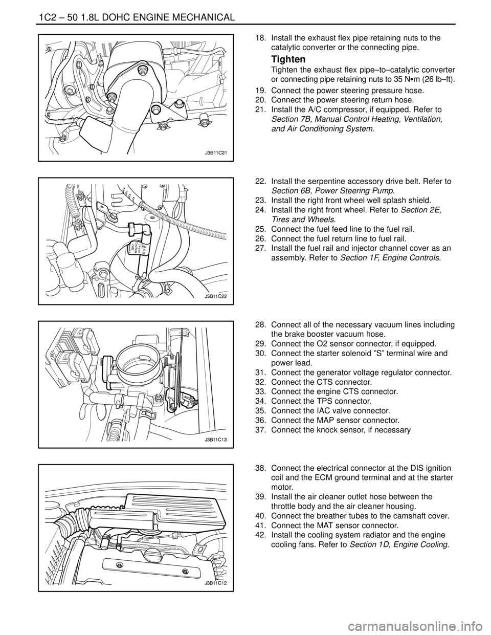
18. Install the exhaust flex pipe retaining nuts to the
catalytic converter or the connecting pipe.
Tighten
Tighten the exhaust flex pipe–to–catalytic converter
or connecting pipe retaining nuts to 35 NSm (26 lb–ft).
19. Connect the power steering pressure hose.
20. Connect the power steering return hose.
21. Install the A/C compressor, if equipped. Refer to
Section 7B, Manual Control Heating, Ventilation,
and Air Conditioning System.
22. Install the serpentine accessory drive belt. Refer to
Section 6B, Power Steering Pump.
23. Install the right front wheel well splash shield.
24. Install the right front wheel. Refer to Section 2E,
Tires and Wheels.
25. Connect the fuel feed line to the fuel rail.
26. Connect the fuel return line to fuel rail.
27. Install the fuel rail and injector channel cover as an
assembly. Refer to Section 1F, Engine Controls.
28. Connect all of the necessary vacuum lines including
the brake booster vacuum hose.
29. Connect the O2 sensor connector, if equipped.
30. Connect the starter solenoid ”S” terminal wire and
power lead.
31. Connect the generator voltage regulator connector.
32. Connect the CTS connector.
33. Connect the engine CTS connector.
34. Connect the TPS connector.
35. Connect the IAC valve connector.
36. Connect the MAP sensor connector.
37. Connect the knock sensor, if necessary
38. Connect the electrical connector at the DIS ignition
coil and the ECM ground terminal and at the starter
motor.
39. Install the air cleaner outlet hose between the
throttle body and the air cleaner housing.
40. Connect the breather tubes to the camshaft cover.
41. Connect the MAT sensor connector.
42. Install the cooling system radiator and the engine
cooling fans. Refer to Section 1D, Engine Cooling.
Page 198 of 2643
ENGINE COOLING 1D – 3
DAEWOO V–121 BL4
DIAGNOSIS
THERMOSTAT TEST
1. Remove the thermostat from the vehicle. Refer to
”Thermostat” in this section.
2. Make sure the valve spring is tight when the ther-
mostat is fully closed. If the spring is not tight, re-
place the thermostat.
3. Suspend the thermostat and a thermometer in a
pan of 50/50 mixture of ethylene glycol and water.
Do not let the thermostat or the thermometer rest
on the bottom of the pan because the uneven con-
centration of heat on the bottom could result in in-
accurate temperature measurements.
4. Heat the pan on a burner.
5. Use the thermometer to measure the temperature
of the heated solution.
6. The thermostat should begin to open at 87°C
(189°F) and it should be fully open at 102°C
(216°F). If it does not open at these temperatures,
replace the thermostat.
SURGE TANK CAP TEST
Tools Required
KM–471 Adapter
The surge tank cap maintains proper pressure, protects
the system from high pressure by opening a pressure
valve, and protects the coolant hoses from collapsing be-
cause of a vacuum.1. Wash any sludge from the surge tank cap and the
valve seat of the vacuum pressure valve for the
surge tank cap.
2. Check for any damage or deformity to the vacuum
pressure valve for the surge tank cap. If any dam-
age or deformity is found, replace the cap.
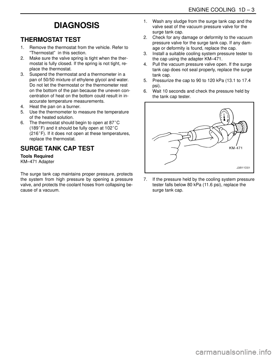
3. Install a suitable cooling system pressure tester to
the cap using the adapter KM–471.
4. Pull the vacuum pressure valve open. If the surge
tank cap does not seal properly, replace the surge
tank cap.
5. Pressurize the cap to 90 to 120 kPa (13.1 to 17.4
psi).
6. Wait 10 seconds and check the pressure held by
the tank cap tester.
7. If the pressure held by the cooling system pressure
tester falls below 80 kPa (11.6 psi), replace the
surge tank cap.