Page 131 of 2643

1.8L DOHC ENGINE MECHANICAL 1C2 – 11
DAEWOO V–121 BL4
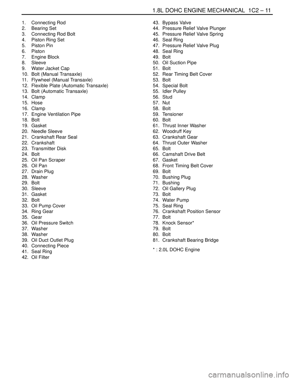
1. Connecting Rod
2. Bearing Set
3. Connecting Rod Bolt
4. Piston Ring Set
5. Piston Pin
6. Piston
7. Engine Block
8. Sleeve
9. Water Jacket Cap
10. Bolt (Manual Transaxle)
11. Flywheel (Manual Transaxle)
12. Flexible Plate (Automatic Transaxle)
13. Bolt (Automatic Transaxle)
14. Clamp
15. Hose
16. Clamp
17. Engine Ventilation Pipe
18. Bolt
19. Gasket
20. Needle Sleeve
21. Crankshaft Rear Seal
22. Crankshaft
23. Transmitter Disk
24. Bolt
25. Oil Pan Scraper
26. Oil Pan
27. Drain Plug
28. Washer
29. Bolt
30. Sleeve
31. Gasket
32. Bolt
33. Oil Pump Cover
34. Ring Gear
35. Gear
36. Oil Pressure Switch
37. Washer
38. Washer
39. Oil Duct Outlet Plug
40. Connecting Piece
41. Seal Ring
42. Oil Filter43. Bypass Valve
44. Pressure Relief Valve Plunger
45. Pressure Relief Valve Spring
46. Seal Ring
47. Pressure Relief Valve Plug
48. Seal Ring
49. Bolt
50. Oil Suction Pipe
51. Bolt
52. Rear Timing Belt Cover
53. Bolt
54. Special Bolt
55. Idler Pulley
56. Stud
57. Nut
58. Bolt
59. Tensioner
60. Bolt
61. Thrust Inner Washer
62. Woodruff Key
63. Crankshaft Gear
64. Thrust Outer Washer
65. Bolt
66. Camshaft Drive Belt
67. Gasket
68. Front Timing Belt Cover
69. Bolt
70. Bushing Plug
71. Bushing
72. Oil Gallery Plug
73. Bolt
74. Water Pump
75. Seal Ring
76. Crankshaft Position Sensor
77. Bolt
78. Knock Sensor*
79. Bolt
80. Bolt
81. Crankshaft Bearing Bridge
* : 2.0L DOHC Engine
Page 134 of 2643

1C2 – 14I1.8L DOHC ENGINE MECHANICAL
DAEWOO V–121 BL4
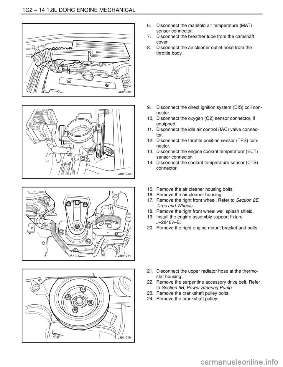
6. Disconnect the manifold air temperature (MAT)
sensor connector.
7. Disconnect the breather tube from the camshaft
cover.
8. Disconnect the air cleaner outlet hose from the
throttle body.
9. Disconnect the direct ignition system (DIS) coil con-
nector.
10. Disconnect the oxygen (O2) sensor connector, if
equipped.
11. Disconnect the idle air control (IAC) valve connec-
tor.
12. Disconnect the throttle position sensor (TPS) con-
nector.
13. Disconnect the engine coolant temperature (ECT)
sensor connector.
14. Disconnect the coolant temperature sensor (CTS)
connector.
15. Remove the air cleaner housing bolts.
16. Remove the air cleaner housing.
17. Remove the right front wheel. Refer to Section 2E,
Tires and Wheels.
18. Remove the right front wheel well splash shield.
19. Install the engine assembly support fixture
J–28467–B.
20. Remove the right engine mount bracket and bolts.
21. Disconnect the upper radiator hose at the thermo-
stat housing.
22. Remove the serpentine accessory drive belt. Refer
to Section 6B, Power Steering Pump.
23. Remove the crankshaft pulley bolts.
24. Remove the crankshaft pulley.
Page 141 of 2643

1.8L DOHC ENGINE MECHANICAL 1C2 – 21
DAEWOO V–121 BL4
39. Install the timing belt.
40. Check and adjust the timing belt tension. Refer to
”Timing Belt Check and Adjust” in this section.
41. Install the front timing belt cover.
42. Install the front timing belt cover bolts.
Tighten
Tighten the front timing belt cover bolts to 6 NSm (53
lb–in).
43. Install the crankshaft pulley.
44. Install the crankshaft pulley bolts.
Tighten
Tighten the crankshaft pulley bolts to 12 NSm (106 lb–
in).
45. Install the right engine mount bracket and retaining
bolts.
Tighten
Tighten the engine mount bracket retaining bolts to 55
NSm (41 lb–ft).
46. Remove the engine assembly lift support
J–28467–B.
47. Install the serpentine accessory drive belt. Refer to
Section 6B, Power Steering Pump.
48. Connect the upper radiator hose to the thermostat
housing.
49. Install the right front wheel well splash shield.
50. Install the right front wheel. Refer to Section 2E,
Tires and Wheels.
51. Install the air cleaner housing.
52. Install the air cleaner housing bolts.
Tighten
Tighten the air cleaner housing bolts to 10 NSm (89 lb–
in).
53. Connect the air cleaner outlet hose to the throttle
body.
54. Connect the breather tube to the camshaft cover.
55. Connect the MAT sensor connector.
Page 147 of 2643

1.8L DOHC ENGINE MECHANICAL 1C2 – 27
DAEWOO V–121 BL4
24. Install the front timing belt cover.
25. Install the front timing belt cover bolts.
Tighten
Tighten the front timing belt cover bolts to 6 NSm (53
lb–in).
26. Install the crankshaft pulley.
27. Install the crankshaft pulley bolt.
Tighten
Tighten the crankshaft pulley bolt to 20 NSm (15 lb–ft).
28. Install the right engine mount bracket. Refer to ”En-
gine Mount” in this section.
29. Install the serpentine accessory drive belt. Refer to
Section 6B, Power Steering Pump.
30. Install the right front wheel well splash shield.
31. Install the right front wheel. Refer to Section 2E,
Tires and Wheels.
32. Install the air cleaner housing.
33. Install the air cleaner housing bolts.
Tighten
Tighten the air cleaner housing bolts to 10 NSm (89 lb–
in).
34. Connect the air cleaner outlet hose to the throttle
body.
35. Connect the breather tube to the camshaft cover.
36. Connect the MAT sensor connector.
37. Connect the negative battery cable.
Page 148 of 2643
1C2 – 28I1.8L DOHC ENGINE MECHANICAL
DAEWOO V–121 BL4
TIMING BELT
Removal Procedure
1. Disconnect the negative battery cable.
2. Disconnect the manifold air temperature (MAT)
sensor connector.
3. Disconnect the air cleaner outlet hose from the
throttle body.
4. Disconnect the breather tube from the camshaft
cover.
5. Remove the air cleaner housing bolts.
6. Remove the air cleaner housing.
7. Remove the right front wheel. Refer to Section 2E,
Tires and Wheels.
8. Remove the right front wheel well splash shield.
9. Remove the serpentine accessory drive belt. Refer
to Section 6B, Power Steering Pump.
10. Remove the crankshaft pulley bolts.
11. Remove the crankshaft pulley.
12. Remove the right engine mount bracket. Refer to
”Engine Mount” in this section.
13. Remove the front timing belt cover bolts.
14. Remove the front timing belt cover.
Page 151 of 2643
1.8L DOHC ENGINE MECHANICAL 1C2 – 31
DAEWOO V–121 BL4
11. Install the crankshaft pulley.
12. Install the crankshaft pulley bolts.
Tighten
Tighten the crankshaft pulley bolts to 20 NSm (15 lb–
ft).
13. Install the serpentine accessory drive belt. Refer to
Section 6B, Power Steering Pump.
14. Install the right front wheel well splash shield. Refer
to Section 9R, Body Front End.
15. Install the right front wheel. Refer to Section 2E,
Tires and Wheels.
16. Install the air cleaner housing.
17. Install the air cleaner housing bolts.
Tighten
Tighten the air cleaner housing bolts to 10 NSm (89 lb–
in).
18. Connect the air cleaner outlet hose to the throttle
body.
19. Connect the breather tube to the camshaft cover.
20. Connect the MAT sensor connector.
21. Connect the negative battery cable.
Page 157 of 2643

1.8L DOHC ENGINE MECHANICAL 1C2 – 37
DAEWOO V–121 BL4
ENGINE MOUNT
Tools Required
J–28467–B Engine Assembly Support Fixture
X–28467–560 Engine Assembly Support Channel
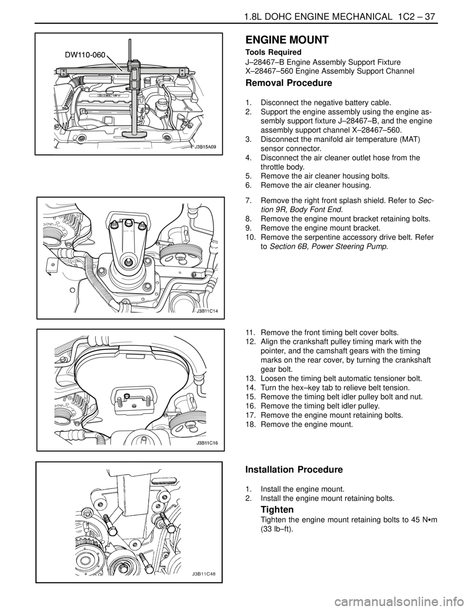
Removal Procedure
1. Disconnect the negative battery cable.
2. Support the engine assembly using the engine as-
sembly support fixture J–28467–B, and the engine
assembly support channel X–28467–560.
3. Disconnect the manifold air temperature (MAT)
sensor connector.
4. Disconnect the air cleaner outlet hose from the
throttle body.
5. Remove the air cleaner housing bolts.
6. Remove the air cleaner housing.
7. Remove the right front splash shield. Refer to Sec-
tion 9R, Body Font End.
8. Remove the engine mount bracket retaining bolts.
9. Remove the engine mount bracket.
10. Remove the serpentine accessory drive belt. Refer
to Section 6B, Power Steering Pump.
11. Remove the front timing belt cover bolts.
12. Align the crankshaft pulley timing mark with the
pointer, and the camshaft gears with the timing
marks on the rear cover, by turning the crankshaft
gear bolt.
13. Loosen the timing belt automatic tensioner bolt.
14. Turn the hex–key tab to relieve belt tension.
15. Remove the timing belt idler pulley bolt and nut.
16. Remove the timing belt idler pulley.
17. Remove the engine mount retaining bolts.
18. Remove the engine mount.
Installation Procedure
1. Install the engine mount.
2. Install the engine mount retaining bolts.
Tighten
Tighten the engine mount retaining bolts to 45 NSm
(33 lb–ft).
Page 168 of 2643

1C2 – 48I1.8L DOHC ENGINE MECHANICAL
DAEWOO V–121 BL4
40. Remove the crankshaft pulley bolts.
41. Remove the crankshaft pulley.
42. Disconnect the vacuum lines at the charcoal canis-
ter purge solenoid.
43. Disconnect the electrical connector at the charcoal
canister purge (CCP) and the exhaust gas recir-
culation (EGR) solenoid.
44. Disconnect the electrical connector at the oil pres-
sure switch.
45. Disconnect the crankshaft position sensor (CPS)
connector.
46. Disconnect the knock sensor connector.
47. Remove the transaxle torque converter bolts, if au-
tomatic transaxle equipped.
48. Remove the transaxle bell housing bolts and the oil
pan flange bolts.
49. Support the transaxle with a floor jack.
50. Install the engine lifting device.
51. Disconnect the right engine mount bracket from the
engine mount by removing the retaining bolt.
52. Remove the right engine mount bracket from the
engine block and frame mount. Refer to Section
5B, Five Speed Manual Transaxle, or Section 5A,
Automatic Transaxle.
53. Separate the engine block from the transaxle. Re-
move the engine.
Installation Procedure
1. Install the engine into the engine compartment.
2. Align the engine alignment pins to the transaxle.
3. Install the transaxle bell housing bolts.
Tighten
Tighten the transaxle bell housing bolts to 75 NSm (55
lb–ft).
4. Install the oil pan flange–to–transaxle bolts.
Tighten
Tighten the oil pan flange–to–transaxle bolts to 40
NSm (30 lb–ft).