2004 CHRYSLER VOYAGER oil filter
[x] Cancel search: oil filterPage 1800 of 2585
STANDARD PROCEDURE - FLUID AND FILTER
SERVICE
NOTE: Refer to the maintenance schedules in
LUBRICATION and MAINTENANCE, or the vehicle
owner's manual, for the recommended maintenance
(fluid/filter change) intervals for this transaxle.
NOTE: Only fluids of the type labeled MoparTATF+4
(Automatic Transmission Fluid) should be used. A
filter change should be made at the time of the
transmission oil change. The magnet (on the inside
of the oil pan) should also be cleaned with a clean,
dry cloth.
NOTE: If the transaxle is disassembled for any rea-
son, the fluid and filter should be changed.
FLUID/FILTER SERVICE (RECOMMENDED)
(1) Raise vehicle on a hoist. Refer to LUBRICA-
TION and MAINTENANCE for proper procedures.
Place a drain container with a large opening, under
transaxle oil pan.
(2) Loosen pan bolts and tap the pan at one corner
to break it loose allowing fluid to drain, then remove
the oil pan.
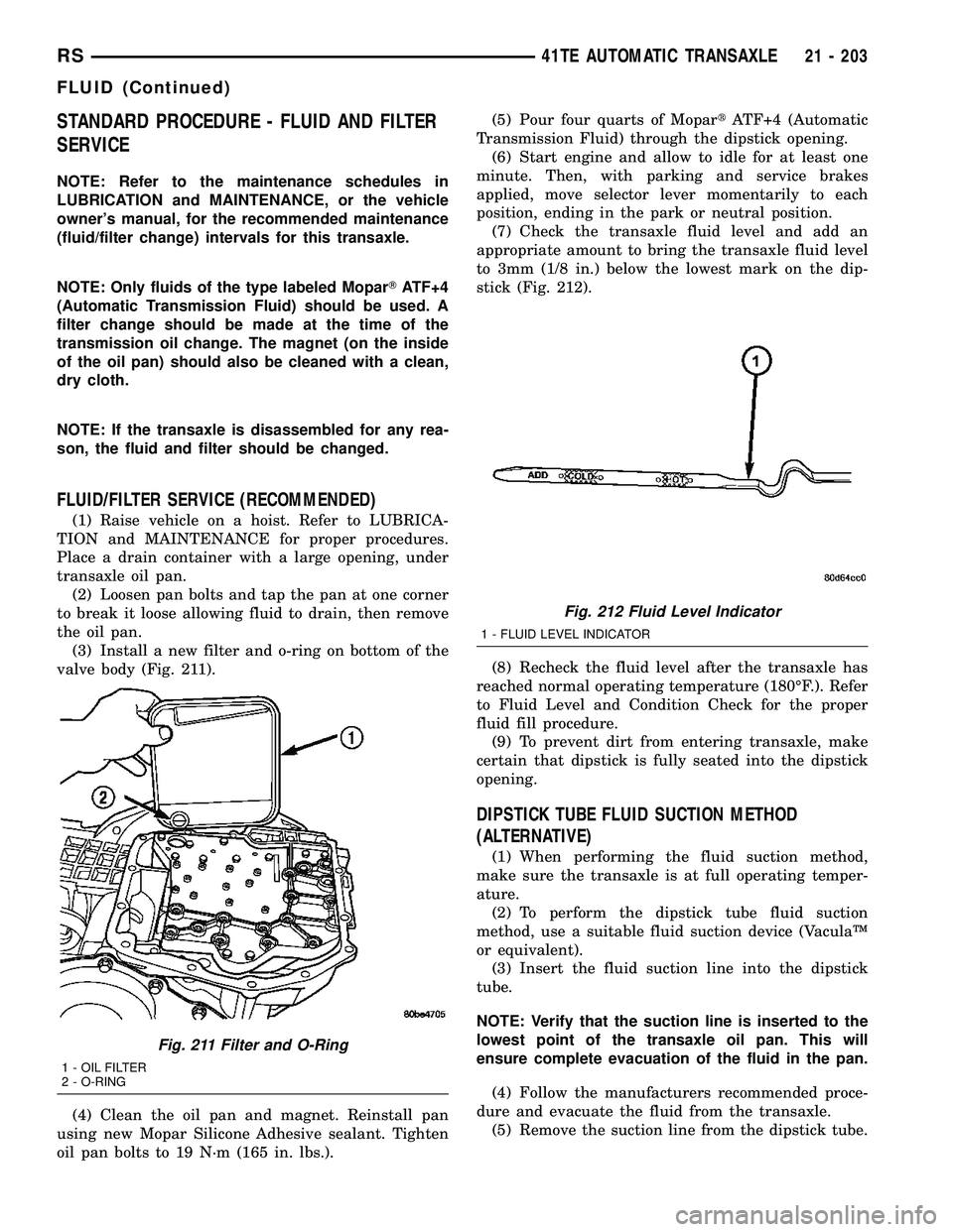
(3) Install a new filter and o-ring on bottom of the
valve body (Fig. 211).
(4) Clean the oil pan and magnet. Reinstall pan
using new Mopar Silicone Adhesive sealant. Tighten
oil pan bolts to 19 N´m (165 in. lbs.).(5) Pour four quarts of MopartATF+4 (Automatic
Transmission Fluid) through the dipstick opening.
(6) Start engine and allow to idle for at least one
minute. Then, with parking and service brakes
applied, move selector lever momentarily to each
position, ending in the park or neutral position.
(7) Check the transaxle fluid level and add an
appropriate amount to bring the transaxle fluid level
to 3mm (1/8 in.) below the lowest mark on the dip-
stick (Fig. 212).
(8) Recheck the fluid level after the transaxle has
reached normal operating temperature (180ÉF.). Refer
to Fluid Level and Condition Check for the proper
fluid fill procedure.
(9) To prevent dirt from entering transaxle, make
certain that dipstick is fully seated into the dipstick
opening.
DIPSTICK TUBE FLUID SUCTION METHOD
(ALTERNATIVE)
(1) When performing the fluid suction method,
make sure the transaxle is at full operating temper-
ature.
(2) To perform the dipstick tube fluid suction
method, use a suitable fluid suction device (VaculaŸ
or equivalent).
(3) Insert the fluid suction line into the dipstick
tube.
NOTE: Verify that the suction line is inserted to the
lowest point of the transaxle oil pan. This will
ensure complete evacuation of the fluid in the pan.
(4) Follow the manufacturers recommended proce-
dure and evacuate the fluid from the transaxle.
(5) Remove the suction line from the dipstick tube.
Fig. 211 Filter and O-Ring
1 - OIL FILTER
2 - O-RING
Fig. 212 Fluid Level Indicator
1 - FLUID LEVEL INDICATOR
RS41TE AUTOMATIC TRANSAXLE21 - 203
FLUID (Continued)
Page 1848 of 2585
MANUAL VALVE
The manual valve is operated by the mechanical
shift linkage. Its primary responsibility is to send
line pressure to the appropriate hydraulic circuits
and solenoids. The valve has three operating ranges
or positions.
CONVERTER CLUTCH SWITCH VALVE
The main responsibility of the converter clutch
switch valve is to control hydraulic pressure applied
to the front (off) side of the converter clutch piston.
Line pressure from the regulator valve is fed to the
torque converter regulator valve, where it passes
through the valve, and is slightly regulated. The
pressure is then directed to the converter clutch
switch valve and to the front side of the converter
clutch piston. This pressure pushes the piston back
and disengages the converter clutch.
CONVERTER CLUTCH CONTROL VALVE
The converter clutch control valve controls the
back (on) side of the torque converter clutch. When
the PCM/TCM energizes or modulates the LR/CC
solenoid to apply the converter clutch piston, both
the converter clutch control valve and the converter
control valve move, allowing pressure to be applied to
the back side of the clutch.
T/C REGULATOR VALVE
The torque converter regulator valve slightly regu-
lates the flow of fluid to the torque converter.
LOW/REVERSE SWITCH VALVE
The low/reverse clutch is applied from different
sources, depending on whether low (1st) gear or
reverse is selected. The low/reverse switch valve
alternates positions depending on from which direc-
tion fluid pressure is applied. By design, when the
valve is shifted by fluid pressure from one channel,
the opposing channel is blocked. The switch valve
alienates the possibility of a sticking ball check, thus
providing consistent application of the low/reverse
clutch under all operating conditions.
REMOVAL
NOTE: If valve body is replaced or reconditioned,
the TCM Quick Learn Procedure must be per-
formed. (Refer to 8 - ELECTRICAL/ELECTRONIC
CONTROL MODULES/TRANSMISSION CONTROL
MODULE - STANDARD PROCEDURE)(1) Disconnect battery negative cable.
(2) Disconnect gearshift cable from manual valve
lever.
(3) Remove manual valve lever from manual shaft.
(4) Raise vehicle on hoist.
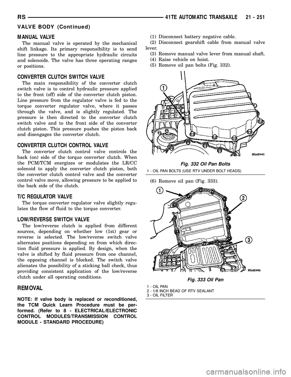
(5) Remove oil pan bolts (Fig. 332).
(6) Remove oil pan (Fig. 333).
Fig. 332 Oil Pan Bolts
1 - OIL PAN BOLTS (USE RTV UNDER BOLT HEADS)
Fig. 333 Oil Pan
1 - OIL PAN
2 - 1/8 INCH BEAD OF RTV SEALANT
3 - OIL FILTER
RS41TE AUTOMATIC TRANSAXLE21 - 251
VALVE BODY (Continued)
Page 1849 of 2585
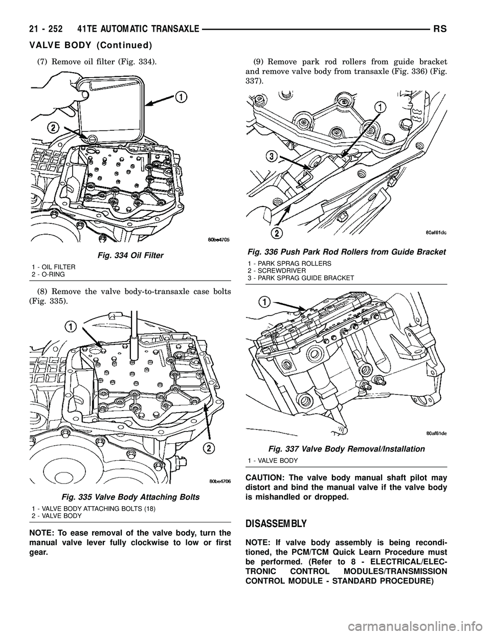
(7) Remove oil filter (Fig. 334).
(8) Remove the valve body-to-transaxle case bolts
(Fig. 335).
NOTE: To ease removal of the valve body, turn the
manual valve lever fully clockwise to low or first
gear.(9) Remove park rod rollers from guide bracket
and remove valve body from transaxle (Fig. 336) (Fig.
337).
CAUTION: The valve body manual shaft pilot may
distort and bind the manual valve if the valve body
is mishandled or dropped.
DISASSEMBLY
NOTE: If valve body assembly is being recondi-
tioned, the PCM/TCM Quick Learn Procedure must
be performed. (Refer to 8 - ELECTRICAL/ELEC-
TRONIC CONTROL MODULES/TRANSMISSION
CONTROL MODULE - STANDARD PROCEDURE)
Fig. 334 Oil Filter
1 - OIL FILTER
2 - O-RING
Fig. 335 Valve Body Attaching Bolts
1 - VALVE BODY ATTACHING BOLTS (18)
2 - VALVE BODY
Fig. 336 Push Park Rod Rollers from Guide Bracket
1 - PARK SPRAG ROLLERS
2 - SCREWDRIVER
3 - PARK SPRAG GUIDE BRACKET
Fig. 337 Valve Body Removal/Installation
1 - VALVE BODY
21 - 252 41TE AUTOMATIC TRANSAXLERS
VALVE BODY (Continued)
Page 1859 of 2585
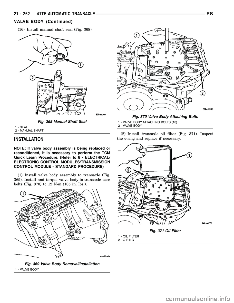
(16) Install manual shaft seal (Fig. 368).
INSTALLATION
NOTE: If valve body assembly is being replaced or
reconditioned, it is necessary to perform the TCM
Quick Learn Procedure. (Refer to 8 - ELECTRICAL/
ELECTRONIC CONTROL MODULES/TRANSMISSION
CONTROL MODULE - STANDARD PROCEDURE)
(1) Install valve body assembly to transaxle (Fig.
369). Install and torque valve body-to-transaxle case
bolts (Fig. 370) to 12 N´m (105 in. lbs.).(2) Install transaxle oil filter (Fig. 371). Inspect
the o-ring and replace if necessary.
Fig. 368 Manual Shaft Seal
1 - SEAL
2 - MANUAL SHAFT
Fig. 369 Valve Body Removal/Installation
1 - VALVE BODY
Fig. 370 Valve Body Attaching Bolts
1 - VALVE BODY ATTACHING BOLTS (18)
2 - VALVE BODY
Fig. 371 Oil Filter
1 - OIL FILTER
2 - O-RING
21 - 262 41TE AUTOMATIC TRANSAXLERS
VALVE BODY (Continued)
Page 1860 of 2585
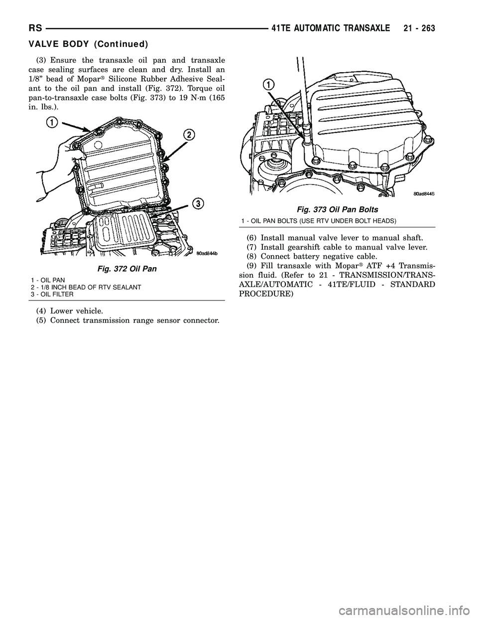
(3) Ensure the transaxle oil pan and transaxle
case sealing surfaces are clean and dry. Install an
1/8º bead of MopartSilicone Rubber Adhesive Seal-
ant to the oil pan and install (Fig. 372). Torque oil
pan-to-transaxle case bolts (Fig. 373) to 19 N´m (165
in. lbs.).
(4) Lower vehicle.
(5) Connect transmission range sensor connector.(6) Install manual valve lever to manual shaft.
(7) Install gearshift cable to manual valve lever.
(8) Connect battery negative cable.
(9) Fill transaxle with MopartATF +4 Transmis-
sion fluid. (Refer to 21 - TRANSMISSION/TRANS-
AXLE/AUTOMATIC - 41TE/FLUID - STANDARD
PROCEDURE)
Fig. 372 Oil Pan
1 - OIL PAN
2 - 1/8 INCH BEAD OF RTV SEALANT
3 - OIL FILTER
Fig. 373 Oil Pan Bolts
1 - OIL PAN BOLTS (USE RTV UNDER BOLT HEADS)
RS41TE AUTOMATIC TRANSAXLE21 - 263
VALVE BODY (Continued)
Page 1885 of 2585
40TE AUTOMATIC TRANSAXLE
TABLE OF CONTENTS
page page
40TE AUTOMATIC TRANSAXLE DESCRIPTION .........................25
OPERATION ...........................27
DIAGNOSIS AND TESTING DIAGNOSIS AND TESTING - 4XTETRANSAXLE GENERAL DIAGNOSIS .......27
DIAGNOSIS AND TESTING - ROAD TEST . . . 27
DIAGNOSIS AND TESTING - HYDRAULIC PRESSURE TESTS ....................28
DIAGNOSIS AND TESTING - CLUTCH AIR PRESSURE TESTS ....................30
DIAGNOSIS AND TESTING - TORQUE CONVERTER HOUSING FLUID LEAKAGE . . . 31
REMOVAL .............................31
DISASSEMBLY .........................34
ASSEMBLY ............................51
INSTALLATION .........................73
SCHEMATICS AND DIAGRAMS 4XTE TRANSAXLE HYDRAULICSCHEMATICS ........................75
SPECIFICATIONS - 41TE TRANSAXLE .......87
SPECIAL TOOLS .......................89
ACCUMULATOR DESCRIPTION .........................94
OPERATION ...........................94
DRIVING CLUTCHES DESCRIPTION .........................95
OPERATION ...........................95
FINAL DRIVE DESCRIPTION .........................95
OPERATION ...........................96
DISASSEMBLY .........................96
ASSEMBLY ............................99
ADJUSTMENTS DIFFERENTIAL BEARING PRELOADMEASUREMENT AND ADJUSTMENT ......100
FLUID STANDARD PROCEDURE FLUID LEVEL AND CONDITION CHECK . . . 102
STANDARD PROCEDURE - FLUID ANDFILTER SERVICE .....................104
GEAR SHIFT CABLE REMOVAL ............................105
HOLDING CLUTCHES DESCRIPTION ........................106
OPERATION ..........................106
INPUT CLUTCH ASSEMBLY DISASSEMBLY ........................107
ASSEMBLY ...........................116 OIL PUMP
DESCRIPTION ........................131
OPERATION ..........................131
DISASSEMBLY ........................131
ASSEMBLY ...........................132
PLANETARY GEARTRAIN DESCRIPTION ........................132
OPERATION ..........................132
SEAL - OIL PUMP REMOVAL ............................133
INSTALLATION ........................133
SHIFT INTERLOCK SOLENOID DESCRIPTION ........................133
OPERATION ..........................134
DIAGNOSIS AND TESTING - BRAKE/ TRANSMISSION SHIFT INTERLOCK
SOLENOID ..........................135
REMOVAL ............................135
INSTALLATION ........................136
SOLENOID/PRESSURE SWITCH ASSY DESCRIPTION ........................137
OPERATION ..........................137
REMOVAL ............................138
INSTALLATION ........................139
SPEED SENSOR - INPUT DESCRIPTION ........................140
OPERATION ..........................140
REMOVAL ............................141
INSTALLATION ........................141
SPEED SENSOR - OUTPUT DESCRIPTION ........................142
OPERATION ..........................142
REMOVAL ............................143
INSTALLATION ........................143
TORQUE CONVERTER DESCRIPTION ........................144
OPERATION ..........................148
REMOVAL ............................149
INSTALLATION ........................149
TRANSMISSION CONTROL RELAY DESCRIPTION ........................150
OPERATION ..........................150
TRANSMISSION RANGE SENSOR DESCRIPTION ........................150
OPERATION ..........................151
REMOVAL ............................151
INSTALLATION ........................152
VALVE BODY DESCRIPTION ........................152
21s - 24 40TE AUTOMATIC TRANSAXLERS
Page 1895 of 2585
(27) Lower engine/transaxle assembly with screw
jack. (28) Obtain helper and/or transmission jack.
Secure transmission jack to transaxle assembly. (29) Remove upper mount bracket from transaxle
(Fig. 14). (30) Remove remaining transaxle bellhousing-to-
engine bolts. (31) Remove transaxle assembly from vehicle.
DISASSEMBLY
NOTE: If transaxle is being overhauled (clutch
and/or seal replacement) or replaced, it is neces-
sary to perform the PCM/TCM Quick Learn Proce-
dure. (Refer t o 8 - ELECTRICAL/ELECTRONIC
CONTROL MODULES/POWERTRAIN/TRANSMIS-
SION CONTROL MODULE - STANDARD PROCE-
DURE)
NOTE: This procedure does not include final drive
(differential) disassembly.
(1) Remove input and output speed sensors.
(2) Remove three (3) solenoid/pressure switch
assembly-to-case bolts. (3) Remove solenoid/pressure switch assembly and
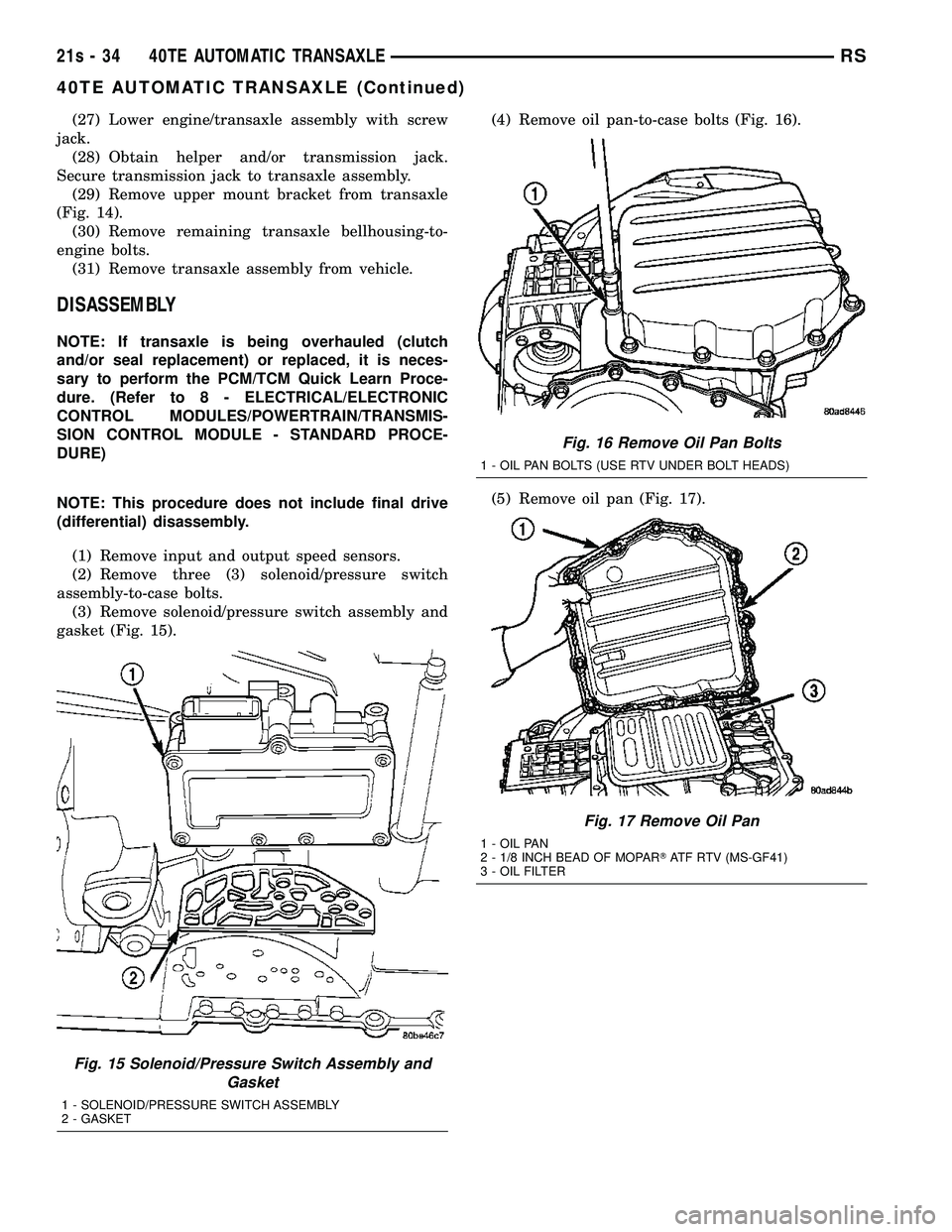
gasket (Fig. 15). (4) Remove oil pan-to-case bolts (Fig. 16).
(5) Remove oil pan (Fig. 17).
Fig. 15 Solenoid/Pressure Switch Assembly and
Gasket
1 - SOLENOID/PRESSURE SWITCH ASSEMBLY
2 - GASKET
Fig. 16 Remove Oil Pan Bolts
1 - OIL PAN BOLTS (USE RTV UNDER BOLT HEADS)
Fig. 17 Remove Oil Pan
1 - OIL PAN
2 - 1/8 INCH BEAD OF MOPAR TATF RTV (MS-GF41)
3 - OIL FILTER
21s - 34 40TE AUTOMATIC TRANSAXLERS
40TE AUTOMATIC TRANSAXLE (Continued)
Page 1896 of 2585

(6) Remove oil filter (Fig. 18).
(7) Turn manual valve fully clock-wise to get park
rod into position for removal. (8) Remove valve body-to-case bolts (Fig. 19). CAUTION: Do not handle the valve body assembly
from the manual valve. Damage can result.
(9) Using a screwdriver, push park rod rollers
away from guide bracket (Fig. 20) and remove valve
body assembly (Fig. 21).
NOTE: Depending on engine application, some
accumulators will have two springs and others will
have one spring. The springs are color-coded
according to application and year. When disassem-
bling, mark accumulator spring location to ease
assembly.
Fig. 18 Remove Filter and O-Ring
1 - OIL FILTER
2 - O-RING
Fig. 19 Remove Valve Body-to-Case Bolts
1 - VALVE BODY ATTACHING BOLTS (18)
2 - VALVE BODY
Fig. 20 Push Park Rod Rollers from Guide Bracket
1 - PARK SPRAG ROLLERS
2 - SCREWDRIVER
3 - PARK SPRAG GUIDE BRACKET
Fig. 21 Valve Body Removal/Installation
1 - VALVE BODY
RS 40TE AUTOMATIC TRANSAXLE21s-35
40TE AUTOMATIC TRANSAXLE (Continued)