2004 CHRYSLER VOYAGER brake sensor
[x] Cancel search: brake sensorPage 1176 of 2585
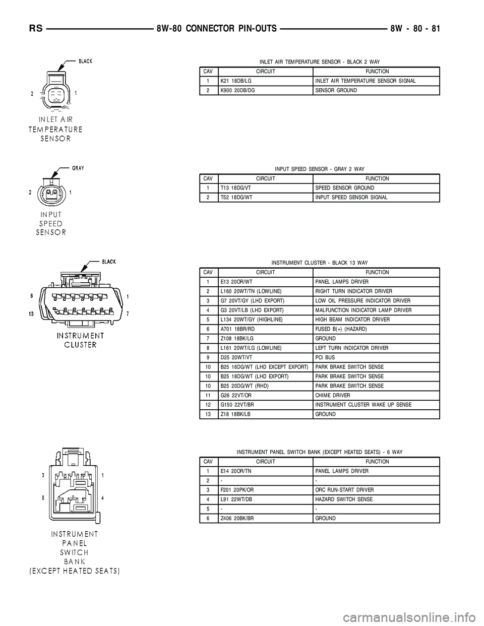
INLET AIR TEMPERATURE SENSOR - BLACK 2 WAY
CAV CIRCUIT FUNCTION
1 K21 18DB/LG INLET AIR TEMPERATURE SENSOR SIGNAL
2 K900 20DB/DG SENSOR GROUND
INPUT SPEED SENSOR - GRAY 2 WAY
CAV CIRCUIT FUNCTION
1 T13 18DG/VT SPEED SENSOR GROUND
2 T52 18DG/WT INPUT SPEED SENSOR SIGNAL
INSTRUMENT CLUSTER - BLACK 13 WAY
CAV CIRCUIT FUNCTION
1 E13 20OR/WT PANEL LAMPS DRIVER
2 L160 20WT/TN (LOWLINE) RIGHT TURN INDICATOR DRIVER
3 G7 20VT/GY (LHD EXPORT) LOW OIL PRESSURE INDICATOR DRIVER
4 G3 20VT/LB (LHD EXPORT) MALFUNCTION INDICATOR LAMP DRIVER
5 L134 20WT/GY (HIGHLINE) HIGH BEAM INDICATOR DRIVER
6 A701 18BR/RD FUSED B(+) (HAZARD)
7 Z108 18BK/LG GROUND
8 L161 20WT/LG (LOWLINE) LEFT TURN INDICATOR DRIVER
9 D25 20WT/VT PCI BUS
10 B25 16DG/WT (LHD EXCEPT EXPORT) PARK BRAKE SWITCH SENSE
10 B25 18DG/WT (LHD EXPORT) PARK BRAKE SWITCH SENSE
10 B25 20DG/WT (RHD) PARK BRAKE SWITCH SENSE
11 G26 22VT/OR CHIME DRIVER
12 G150 22VT/BR INSTRUMENT CLUSTER WAKE UP SENSE
13 Z18 18BK/LB GROUND
INSTRUMENT PANEL SWITCH BANK (EXCEPT HEATED SEATS)-6WAY
CAV CIRCUIT FUNCTION
1 E14 20OR/TN PANEL LAMPS DRIVER
2- -
3 F201 20PK/OR ORC RUN-START DRIVER
4 L91 22WT/DB HAZARD SWITCH SENSE
5- -
6 Z406 20BK/BR GROUND
RS8W-80 CONNECTOR PIN-OUTS8W-80-81
Page 1186 of 2585
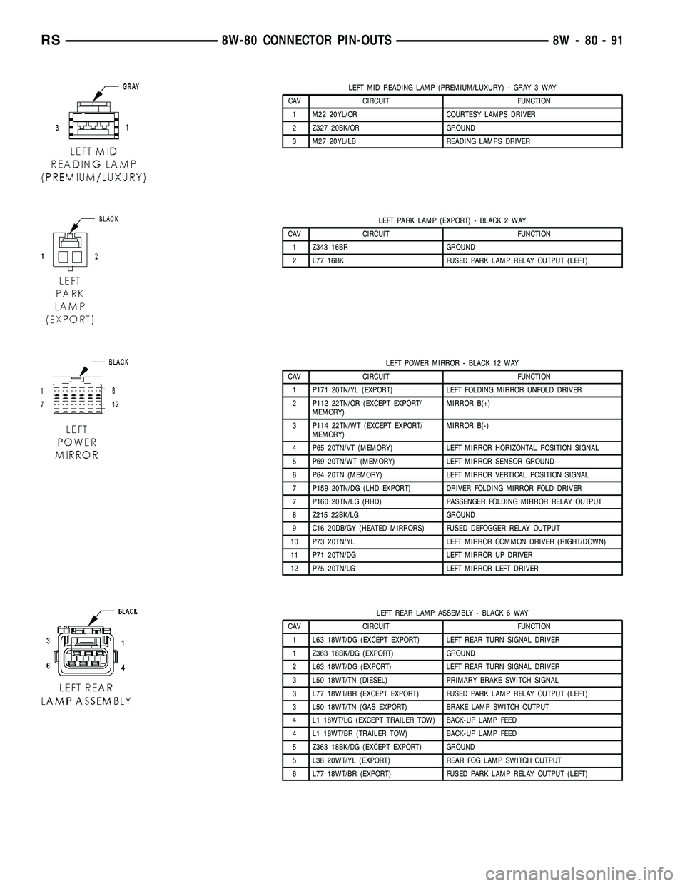
LEFT MID READING LAMP (PREMIUM/LUXURY) - GRAY 3 WAY
CAV CIRCUIT FUNCTION
1 M22 20YL/OR COURTESY LAMPS DRIVER
2 Z327 20BK/OR GROUND
3 M27 20YL/LB READING LAMPS DRIVER
LEFT PARK LAMP (EXPORT) - BLACK 2 WAY
CAV CIRCUIT FUNCTION
1 Z343 16BR GROUND
2 L77 16BK FUSED PARK LAMP RELAY OUTPUT (LEFT)
LEFT POWER MIRROR - BLACK 12 WAY
CAV CIRCUIT FUNCTION
1 P171 20TN/YL (EXPORT) LEFT FOLDING MIRROR UNFOLD DRIVER
2 P112 22TN/OR (EXCEPT EXPORT/
MEMORY)MIRROR B(+)
3 P114 22TN/WT (EXCEPT EXPORT/
MEMORY)MIRROR B(-)
4 P65 20TN/VT (MEMORY) LEFT MIRROR HORIZONTAL POSITION SIGNAL
5 P69 20TN/WT (MEMORY) LEFT MIRROR SENSOR GROUND
6 P64 20TN (MEMORY) LEFT MIRROR VERTICAL POSITION SIGNAL
7 P159 20TN/DG (LHD EXPORT) DRIVER FOLDING MIRROR FOLD DRIVER
7 P160 20TN/LG (RHD) PASSENGER FOLDING MIRROR RELAY OUTPUT
8 Z215 22BK/LG GROUND
9 C16 20DB/GY (HEATED MIRRORS) FUSED DEFOGGER RELAY OUTPUT
10 P73 20TN/YL LEFT MIRROR COMMON DRIVER (RIGHT/DOWN)
11 P71 20TN/DG LEFT MIRROR UP DRIVER
12 P75 20TN/LG LEFT MIRROR LEFT DRIVER
LEFT REAR LAMP ASSEMBLY - BLACK 6 WAY
CAV CIRCUIT FUNCTION
1 L63 18WT/DG (EXCEPT EXPORT) LEFT REAR TURN SIGNAL DRIVER
1 Z363 18BK/DG (EXPORT) GROUND
2 L63 18WT/DG (EXPORT) LEFT REAR TURN SIGNAL DRIVER
3 L50 18WT/TN (DIESEL) PRIMARY BRAKE SWITCH SIGNAL
3 L77 18WT/BR (EXCEPT EXPORT) FUSED PARK LAMP RELAY OUTPUT (LEFT)
3 L50 18WT/TN (GAS EXPORT) BRAKE LAMP SWITCH OUTPUT
4 L1 18WT/LG (EXCEPT TRAILER TOW) BACK-UP LAMP FEED
4 L1 18WT/BR (TRAILER TOW) BACK-UP LAMP FEED
5 Z363 18BK/DG (EXCEPT EXPORT) GROUND
5 L38 20WT/YL (EXPORT) REAR FOG LAMP SWITCH OUTPUT
6 L77 18WT/BR (EXPORT) FUSED PARK LAMP RELAY OUTPUT (LEFT)
RS8W-80 CONNECTOR PIN-OUTS8W-80-91
Page 1232 of 2585
8W-91 CONNECTOR/GROUND/SPLICE LOCATION
TABLE OF CONTENTS
page
CONNECTOR/GROUND/SPLICE LOCATION
DESCRIPTION..........................1
CONNECTOR/GROUND/SPLICE
LOCATION
DESCRIPTION
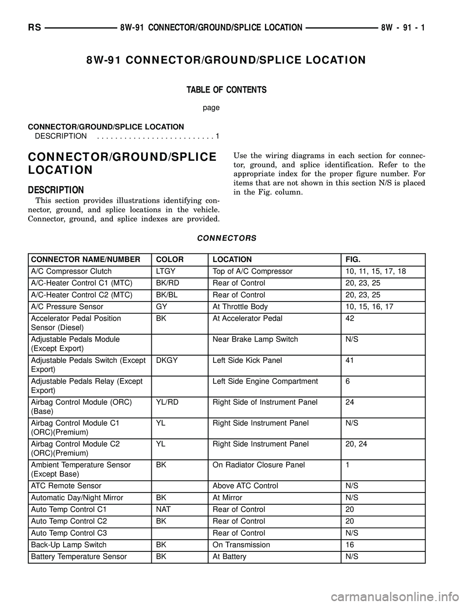
This section provides illustrations identifying con-
nector, ground, and splice locations in the vehicle.
Connector, ground, and splice indexes are provided.Use the wiring diagrams in each section for connec-
tor, ground, and splice identification. Refer to the
appropriate index for the proper figure number. For
items that are not shown in this section N/S is placed
in the Fig. column.
CONNECTORS
CONNECTOR NAME/NUMBER COLOR LOCATION FIG.
A/C Compressor Clutch LTGY Top of A/C Compressor 10, 11, 15, 17, 18
A/C-Heater Control C1 (MTC) BK/RD Rear of Control 20, 23, 25
A/C-Heater Control C2 (MTC) BK/BL Rear of Control 20, 23, 25
A/C Pressure Sensor GY At Throttle Body 10, 15, 16, 17
Accelerator Pedal Position
Sensor (Diesel)BK At Accelerator Pedal 42
Adjustable Pedals Module
(Except Export)Near Brake Lamp Switch N/S
Adjustable Pedals Switch (Except
Export)DKGY Left Side Kick Panel 41
Adjustable Pedals Relay (Except
Export)Left Side Engine Compartment 6
Airbag Control Module (ORC)
(Base)YL/RD Right Side of Instrument Panel 24
Airbag Control Module C1
(ORC)(Premium)YL Right Side Instrument Panel N/S
Airbag Control Module C2
(ORC)(Premium)YL Right Side Instrument Panel 20, 24
Ambient Temperature Sensor
(Except Base)BK On Radiator Closure Panel 1
ATC Remote Sensor Above ATC Control N/S
Automatic Day/Night Mirror BK At Mirror N/S
Auto Temp Control C1 NAT Rear of Control 20
Auto Temp Control C2 BK Rear of Control 20
Auto Temp Control C3 Rear of Control N/S
Back-Up Lamp Switch BK On Transmission 16
Battery Temperature Sensor BK At Battery N/S
RS8W-91 CONNECTOR/GROUND/SPLICE LOCATION8W-91-1
Page 1233 of 2585
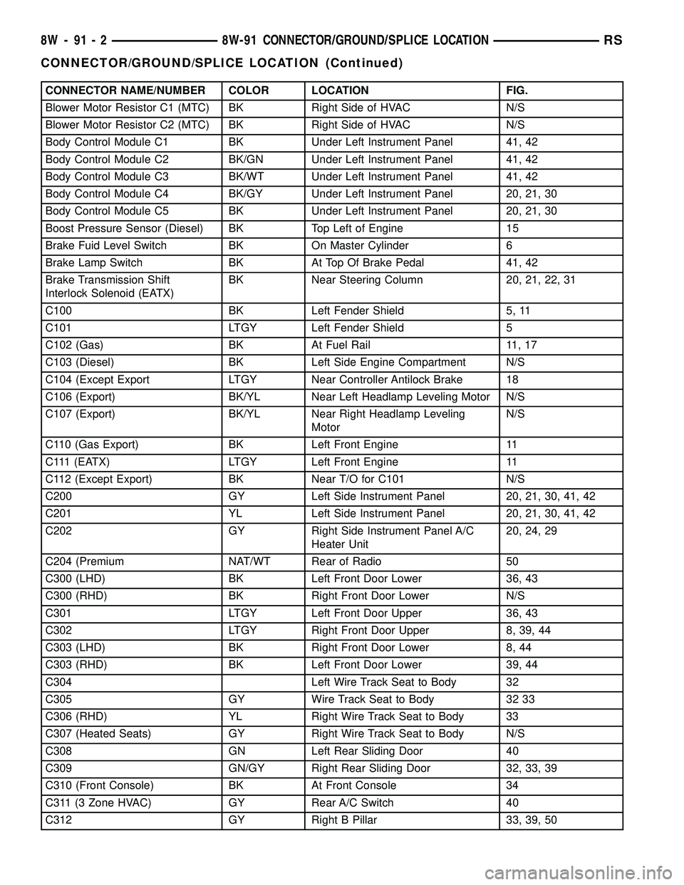
CONNECTOR NAME/NUMBER COLOR LOCATION FIG.
Blower Motor Resistor C1 (MTC) BK Right Side of HVAC N/S
Blower Motor Resistor C2 (MTC) BK Right Side of HVAC N/S
Body Control Module C1 BK Under Left Instrument Panel 41, 42
Body Control Module C2 BK/GN Under Left Instrument Panel 41, 42
Body Control Module C3 BK/WT Under Left Instrument Panel 41, 42
Body Control Module C4 BK/GY Under Left Instrument Panel 20, 21, 30
Body Control Module C5 BK Under Left Instrument Panel 20, 21, 30
Boost Pressure Sensor (Diesel) BK Top Left of Engine 15
Brake Fuid Level Switch BK On Master Cylinder 6
Brake Lamp Switch BK At Top Of Brake Pedal 41, 42
Brake Transmission Shift
Interlock Solenoid (EATX)BK Near Steering Column 20, 21, 22, 31
C100 BK Left Fender Shield 5, 11
C101 LTGY Left Fender Shield 5
C102 (Gas) BK At Fuel Rail 11, 17
C103 (Diesel) BK Left Side Engine Compartment N/S
C104 (Except Export LTGY Near Controller Antilock Brake 18
C106 (Export) BK/YL Near Left Headlamp Leveling Motor N/S
C107 (Export) BK/YL Near Right Headlamp Leveling
MotorN/S
C110 (Gas Export) BK Left Front Engine 11
C111 (EATX) LTGY Left Front Engine 11
C112 (Except Export) BK Near T/O for C101 N/S
C200 GY Left Side Instrument Panel 20, 21, 30, 41, 42
C201 YL Left Side Instrument Panel 20, 21, 30, 41, 42
C202 GY Right Side Instrument Panel A/C
Heater Unit20, 24, 29
C204 (Premium NAT/WT Rear of Radio 50
C300 (LHD) BK Left Front Door Lower 36, 43
C300 (RHD) BK Right Front Door Lower N/S
C301 LTGY Left Front Door Upper 36, 43
C302 LTGY Right Front Door Upper 8, 39, 44
C303 (LHD) BK Right Front Door Lower 8, 44
C303 (RHD) BK Left Front Door Lower 39, 44
C304 Left Wire Track Seat to Body 32
C305 GY Wire Track Seat to Body 32 33
C306 (RHD) YL Right Wire Track Seat to Body 33
C307 (Heated Seats) GY Right Wire Track Seat to Body N/S
C308 GN Left Rear Sliding Door 40
C309 GN/GY Right Rear Sliding Door 32, 33, 39
C310 (Front Console) BK At Front Console 34
C311 (3 Zone HVAC) GY Rear A/C Switch 40
C312 GY Right B Pillar 33, 39, 50
8W - 91 - 2 8W-91 CONNECTOR/GROUND/SPLICE LOCATIONRS
CONNECTOR/GROUND/SPLICE LOCATION (Continued)
Page 1234 of 2585
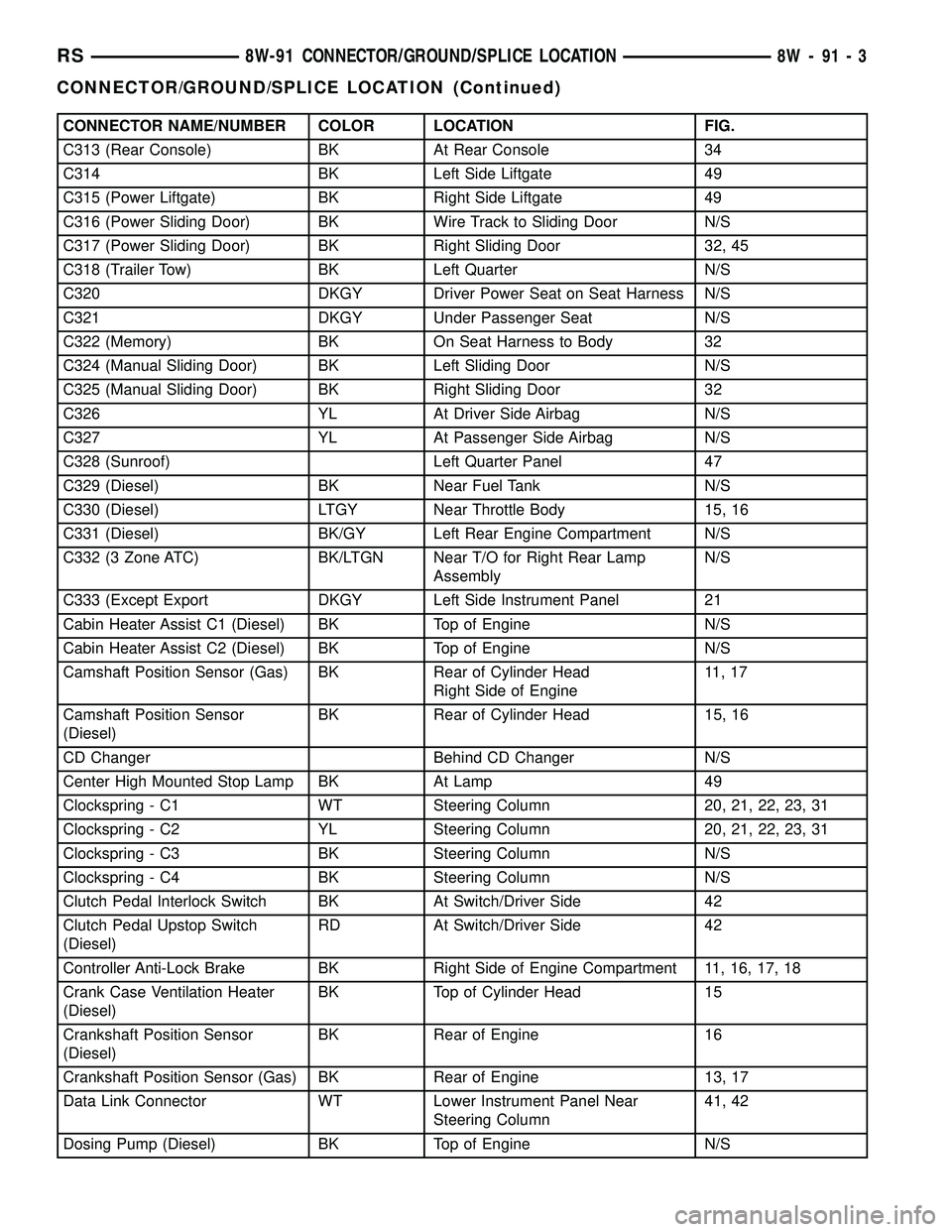
CONNECTOR NAME/NUMBER COLOR LOCATION FIG.
C313 (Rear Console) BK At Rear Console 34
C314 BK Left Side Liftgate 49
C315 (Power Liftgate) BK Right Side Liftgate 49
C316 (Power Sliding Door) BK Wire Track to Sliding Door N/S
C317 (Power Sliding Door) BK Right Sliding Door 32, 45
C318 (Trailer Tow) BK Left Quarter N/S
C320 DKGY Driver Power Seat on Seat Harness N/S
C321 DKGY Under Passenger Seat N/S
C322 (Memory) BK On Seat Harness to Body 32
C324 (Manual Sliding Door) BK Left Sliding Door N/S
C325 (Manual Sliding Door) BK Right Sliding Door 32
C326 YL At Driver Side Airbag N/S
C327 YL At Passenger Side Airbag N/S
C328 (Sunroof) Left Quarter Panel 47
C329 (Diesel) BK Near Fuel Tank N/S
C330 (Diesel) LTGY Near Throttle Body 15, 16
C331 (Diesel) BK/GY Left Rear Engine Compartment N/S
C332 (3 Zone ATC) BK/LTGN Near T/O for Right Rear Lamp
AssemblyN/S
C333 (Except Export DKGY Left Side Instrument Panel 21
Cabin Heater Assist C1 (Diesel) BK Top of Engine N/S
Cabin Heater Assist C2 (Diesel) BK Top of Engine N/S
Camshaft Position Sensor (Gas) BK Rear of Cylinder Head
Right Side of Engine11 , 1 7
Camshaft Position Sensor
(Diesel)BK Rear of Cylinder Head 15, 16
CD Changer Behind CD Changer N/S
Center High Mounted Stop Lamp BK At Lamp 49
Clockspring - C1 WT Steering Column 20, 21, 22, 23, 31
Clockspring - C2 YL Steering Column 20, 21, 22, 23, 31
Clockspring - C3 BK Steering Column N/S
Clockspring - C4 BK Steering Column N/S
Clutch Pedal Interlock Switch BK At Switch/Driver Side 42
Clutch Pedal Upstop Switch
(Diesel)RD At Switch/Driver Side 42
Controller Anti-Lock Brake BK Right Side of Engine Compartment 11, 16, 17, 18
Crank Case Ventilation Heater
(Diesel)BK Top of Cylinder Head 15
Crankshaft Position Sensor
(Diesel)BK Rear of Engine 16
Crankshaft Position Sensor (Gas) BK Rear of Engine 13, 17
Data Link Connector WT Lower Instrument Panel Near
Steering Column41, 42
Dosing Pump (Diesel) BK Top of Engine N/S
RS8W-91 CONNECTOR/GROUND/SPLICE LOCATION8W-91-3
CONNECTOR/GROUND/SPLICE LOCATION (Continued)
Page 1243 of 2585
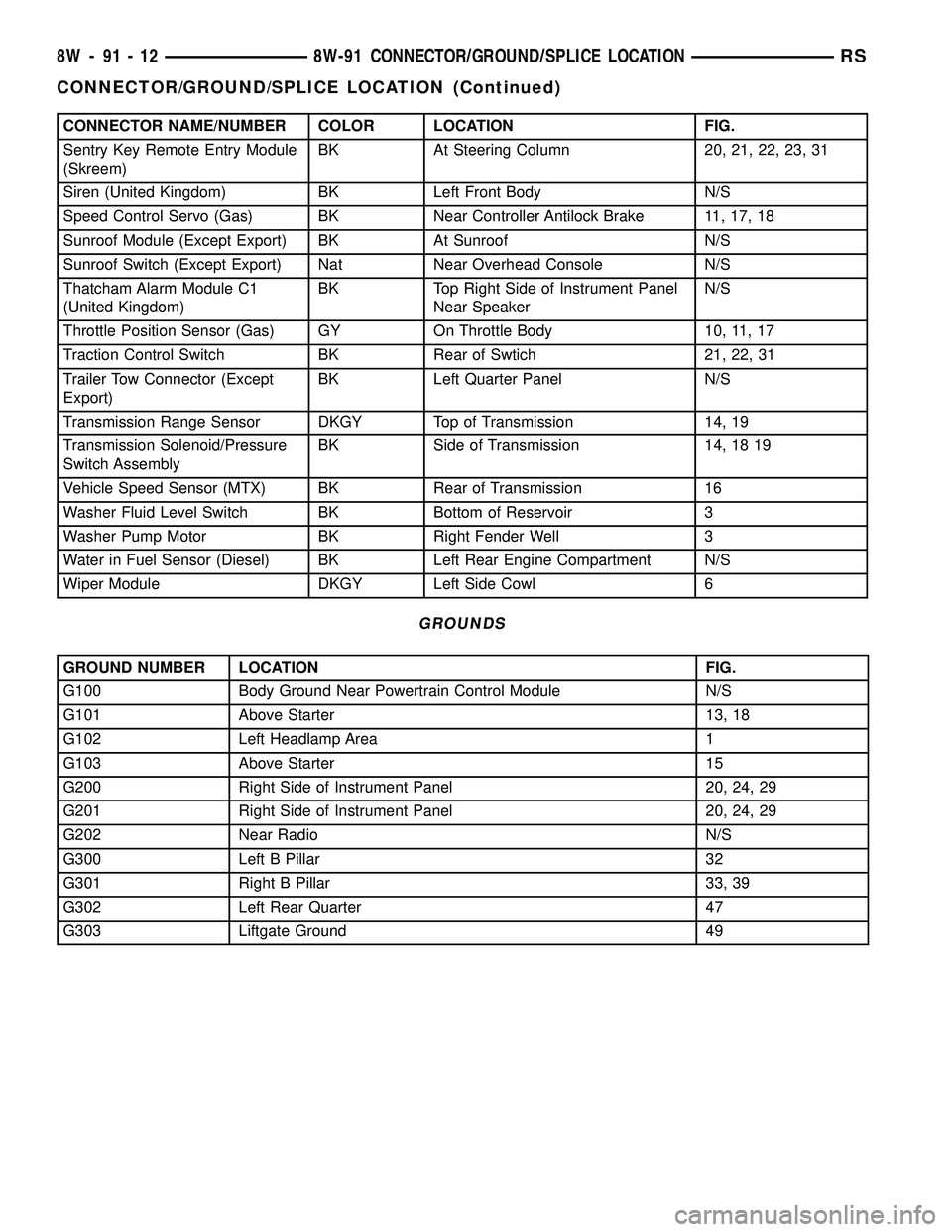
CONNECTOR NAME/NUMBER COLOR LOCATION FIG.
Sentry Key Remote Entry Module
(Skreem)BK At Steering Column 20, 21, 22, 23, 31
Siren (United Kingdom) BK Left Front Body N/S
Speed Control Servo (Gas) BK Near Controller Antilock Brake 11, 17, 18
Sunroof Module (Except Export) BK At Sunroof N/S
Sunroof Switch (Except Export) Nat Near Overhead Console N/S
Thatcham Alarm Module C1
(United Kingdom)BK Top Right Side of Instrument Panel
Near SpeakerN/S
Throttle Position Sensor (Gas) GY On Throttle Body 10, 11, 17
Traction Control Switch BK Rear of Swtich 21, 22, 31
Trailer Tow Connector (Except
Export)BK Left Quarter Panel N/S
Transmission Range Sensor DKGY Top of Transmission 14, 19
Transmission Solenoid/Pressure
Switch AssemblyBK Side of Transmission 14, 18 19
Vehicle Speed Sensor (MTX) BK Rear of Transmission 16
Washer Fluid Level Switch BK Bottom of Reservoir 3
Washer Pump Motor BK Right Fender Well 3
Water in Fuel Sensor (Diesel) BK Left Rear Engine Compartment N/S
Wiper Module DKGY Left Side Cowl 6
GROUNDS
GROUND NUMBER LOCATION FIG.
G100 Body Ground Near Powertrain Control Module N/S
G101 Above Starter 13, 18
G102 Left Headlamp Area 1
G103 Above Starter 15
G200 Right Side of Instrument Panel 20, 24, 29
G201 Right Side of Instrument Panel 20, 24, 29
G202 Near Radio N/S
G300 Left B Pillar 32
G301 Right B Pillar 33, 39
G302 Left Rear Quarter 47
G303 Liftgate Ground 49
8W - 91 - 12 8W-91 CONNECTOR/GROUND/SPLICE LOCATIONRS
CONNECTOR/GROUND/SPLICE LOCATION (Continued)
Page 1355 of 2585
INTAKE MANIFOLD
DESCRIPTION
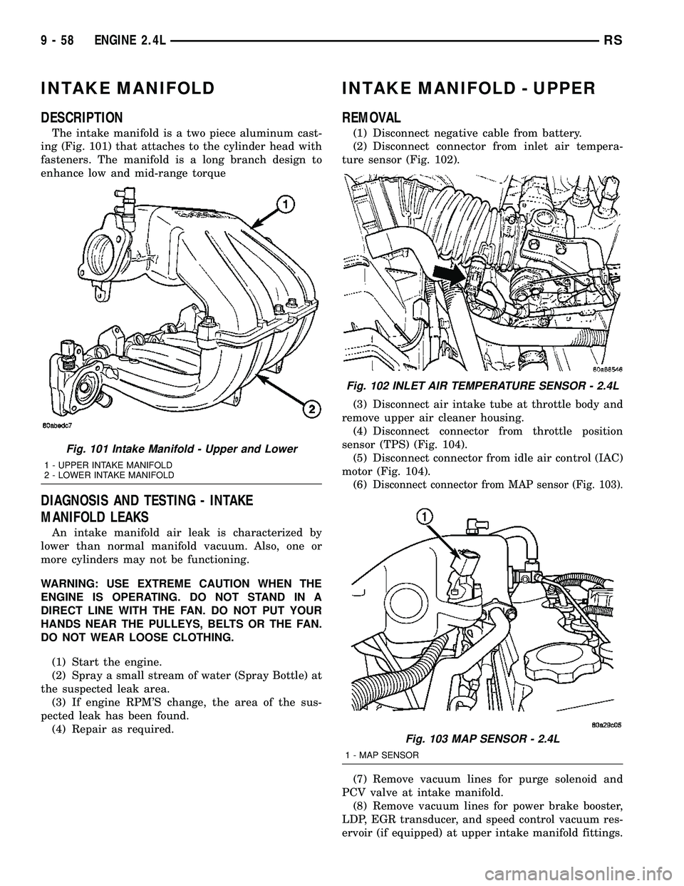
The intake manifold is a two piece aluminum cast-
ing (Fig. 101) that attaches to the cylinder head with
fasteners. The manifold is a long branch design to
enhance low and mid-range torque
DIAGNOSIS AND TESTING - INTAKE
MANIFOLD LEAKS
An intake manifold air leak is characterized by
lower than normal manifold vacuum. Also, one or
more cylinders may not be functioning.
WARNING: USE EXTREME CAUTION WHEN THE
ENGINE IS OPERATING. DO NOT STAND IN A
DIRECT LINE WITH THE FAN. DO NOT PUT YOUR
HANDS NEAR THE PULLEYS, BELTS OR THE FAN.
DO NOT WEAR LOOSE CLOTHING.
(1) Start the engine.
(2) Spray a small stream of water (Spray Bottle) at
the suspected leak area.
(3) If engine RPM'S change, the area of the sus-
pected leak has been found.
(4) Repair as required.
INTAKE MANIFOLD - UPPER
REMOVAL
(1) Disconnect negative cable from battery.
(2) Disconnect connector from inlet air tempera-
ture sensor (Fig. 102).
(3) Disconnect air intake tube at throttle body and
remove upper air cleaner housing.
(4) Disconnect connector from throttle position
sensor (TPS) (Fig. 104).
(5) Disconnect connector from idle air control (IAC)
motor (Fig. 104).
(6)
Disconnect connector from MAP sensor (Fig. 103).
(7) Remove vacuum lines for purge solenoid and
PCV valve at intake manifold.
(8) Remove vacuum lines for power brake booster,
LDP, EGR transducer, and speed control vacuum res-
ervoir (if equipped) at upper intake manifold fittings.
Fig. 101 Intake Manifold - Upper and Lower
1 - UPPER INTAKE MANIFOLD
2 - LOWER INTAKE MANIFOLD
Fig. 102 INLET AIR TEMPERATURE SENSOR - 2.4L
Fig. 103 MAP SENSOR - 2.4L
1 - MAP SENSOR
9 - 58 ENGINE 2.4LRS
Page 1356 of 2585
(9) Disconnect throttle and speed control (if
equipped) cables from throttle lever and bracket.
(Refer to 14 - FUEL SYSTEM/FUEL INJECTION/
THROTTLE CONTROL CABLE - REMOVAL)
(10) Remove the EGR tube. (Refer to 25 - EMIS-
SIONS CONTROL/EXHAUST GAS RECIRCULA-
TION/TUBE - REMOVAL)
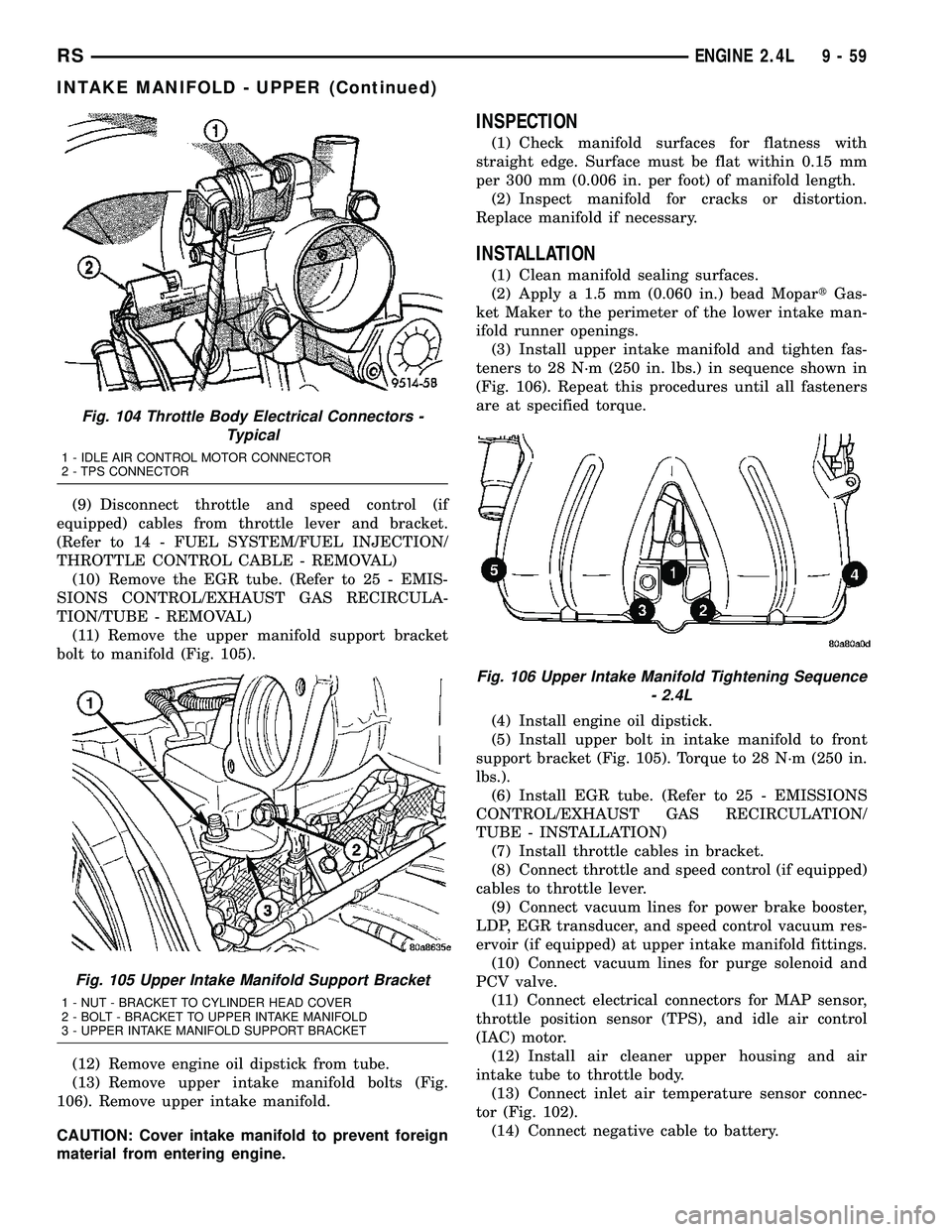
(11) Remove the upper manifold support bracket
bolt to manifold (Fig. 105).
(12) Remove engine oil dipstick from tube.
(13) Remove upper intake manifold bolts (Fig.
106). Remove upper intake manifold.
CAUTION: Cover intake manifold to prevent foreign
material from entering engine.
INSPECTION
(1) Check manifold surfaces for flatness with
straight edge. Surface must be flat within 0.15 mm
per 300 mm (0.006 in. per foot) of manifold length.
(2) Inspect manifold for cracks or distortion.
Replace manifold if necessary.
INSTALLATION
(1) Clean manifold sealing surfaces.
(2) Apply a 1.5 mm (0.060 in.) bead MopartGas-
ket Maker to the perimeter of the lower intake man-
ifold runner openings.
(3) Install upper intake manifold and tighten fas-
teners to 28 N´m (250 in. lbs.) in sequence shown in
(Fig. 106). Repeat this procedures until all fasteners
are at specified torque.
(4) Install engine oil dipstick.
(5) Install upper bolt in intake manifold to front
support bracket (Fig. 105). Torque to 28 N´m (250 in.
lbs.).
(6) Install EGR tube. (Refer to 25 - EMISSIONS
CONTROL/EXHAUST GAS RECIRCULATION/
TUBE - INSTALLATION)
(7) Install throttle cables in bracket.
(8) Connect throttle and speed control (if equipped)
cables to throttle lever.
(9) Connect vacuum lines for power brake booster,
LDP, EGR transducer, and speed control vacuum res-
ervoir (if equipped) at upper intake manifold fittings.
(10) Connect vacuum lines for purge solenoid and
PCV valve.
(11) Connect electrical connectors for MAP sensor,
throttle position sensor (TPS), and idle air control
(IAC) motor.
(12) Install air cleaner upper housing and air
intake tube to throttle body.
(13) Connect inlet air temperature sensor connec-
tor (Fig. 102).
(14) Connect negative cable to battery.
Fig. 104 Throttle Body Electrical Connectors -
Typical
1 - IDLE AIR CONTROL MOTOR CONNECTOR
2 - TPS CONNECTOR
Fig. 105 Upper Intake Manifold Support Bracket
1 - NUT - BRACKET TO CYLINDER HEAD COVER
2 - BOLT - BRACKET TO UPPER INTAKE MANIFOLD
3 - UPPER INTAKE MANIFOLD SUPPORT BRACKET
Fig. 106 Upper Intake Manifold Tightening Sequence
- 2.4L
RSENGINE 2.4L9-59
INTAKE MANIFOLD - UPPER (Continued)