2004 CHRYSLER VOYAGER ECO mode
[x] Cancel search: ECO modePage 1526 of 2585
1 second. Therefore, battery voltage is not supplied to
the fuel pump, ignition coil, fuel injectors and heated
oxygen sensors.
ENGINE START-UP MODE
This is an OPEN LOOP mode. If the vehicle is in
park or neutral (automatic transaxles) or the clutch
pedal is depressed (manual transaxles) the ignition
switch energizes the starter relay when the engine is
not running. The following actions occur when the
starter motor is engaged.
²If the PCM receives the camshaft position sensor
and crankshaft position sensor signals, it energizes
the Auto Shutdown (ASD) relay and fuel pump relay.
If the PCM does not receive both signals within
approximately one second, it will not energize the
ASD relay and fuel pump relay. The ASD and fuel
pump relays supply battery voltage to the fuel pump,
fuel injectors, ignition coil, (EGR solenoid and PCV
heater if equipped) and heated oxygen sensors.
²The PCM energizes the injectors (on the 69É
degree falling edge) for a calculated pulse width until
it determines crankshaft position from the camshaft
position sensor and crankshaft position sensor sig-
nals. The PCM determines crankshaft position within
1 engine revolution.
²After determining crankshaft position, the PCM
begins energizing the injectors in sequence. It adjusts
injector pulse width and controls injector synchroni-
zation by turning the individual ground paths to the
injectors On and Off.
²When the engine idles within 64 RPM of its
target RPM, the PCM compares current MAP sensor
value with the atmospheric pressure value received
during the Ignition Switch On (zero RPM) mode.
Once the ASD and fuel pump relays have been
energized, the PCM determines injector pulse width
based on the following:
²MAP
²Engine RPM
²Battery voltage
²Engine coolant temperature
²Inlet/Intake air temperature (IAT)
²Throttle position
²The number of engine revolutions since cranking
was initiated
During Start-up the PCM maintains ignition tim-
ing at 9É BTDC.
ENGINE WARM-UP MODE
This is an OPEN LOOP mode. The following inputs
are received by the PCM:
²Manifold Absolute Pressure (MAP)
²Crankshaft position (engine speed)
²Engine coolant temperature
²Inlet/Intake air temperature (IAT)²Camshaft position
²Knock sensor
²Throttle position
²A/C switch status
²Battery voltage
²Vehicle speed
²Speed control
²O2 sensors
The PCM adjusts injector pulse width and controls
injector synchronization by turning the individual
ground paths to the injectors On and Off.
The PCM adjusts ignition timing and engine idle
speed. Engine idle speed is adjusted through the idle
air control motor.
CRUISE OR IDLE MODE
When the engine is at operating temperature this
is a CLOSED LOOP mode. During cruising or idle
the following inputs are received by the PCM:
²Manifold absolute pressure
²Crankshaft position (engine speed)
²Inlet/Intake air temperature
²Engine coolant temperature
²Camshaft position
²Knock sensor
²Throttle position
²Exhaust gas oxygen content (O2 sensors)
²A/C switch status
²Battery voltage
²Vehicle speed
The PCM adjusts injector pulse width and controls
injector synchronization by turning the individual
ground paths to the injectors On and Off.
The PCM adjusts engine idle speed and ignition
timing. The PCM adjusts the air/fuel ratio according
to the oxygen content in the exhaust gas (measured
by the upstream and downstream heated oxygen sen-
sor).
The PCM monitors for engine misfire. During
active misfire and depending on the severity, the
PCM either continuously illuminates or flashes the
malfunction indicator lamp (Check Engine light on
instrument panel). Also, the PCM stores an engine
misfire DTC in memory, if 2nd trip with fault.
The PCM performs several diagnostic routines.
They include:
²Oxygen sensor monitor
²Downstream heated oxygen sensor diagnostics
during open loop operation (except for shorted)
²Fuel system monitor
²EGR monitor (if equipped)
²Purge system monitor
²Catalyst efficiency monitor
²All inputs monitored for proper voltage range,
rationality.
RSFUEL INJECTION14-19
FUEL INJECTION (Continued)
Page 1527 of 2585
²All monitored components (refer to the Emission
section for On-Board Diagnostics).
The PCM compares the upstream and downstream
heated oxygen sensor inputs to measure catalytic
convertor efficiency. If the catalyst efficiency drops
below the minimum acceptable percentage, the PCM
stores a diagnostic trouble code in memory, after 2
trips.
During certain idle conditions, the PCM may enter
a variable idle speed strategy. During variable idle
speed strategy the PCM adjusts engine speed based
on the following inputs.
²A/C status
²Battery voltage
²Battery temperature or Calculated Battery Tem-
perature
²Engine coolant temperature
²Engine run time
²Inlet/Intake air temperature
²Vehicle mileage
ACCELERATION MODE
This is a CLOSED LOOP mode. The PCM recog-
nizes an abrupt increase in Throttle Position sensor
output voltage or MAP sensor output voltage as a
demand for increased engine output and vehicle
acceleration. The PCM increases injector pulse width
in response to increased fuel demand.
²Wide Open Throttle-open loop
DECELERATION MODE
This is a CLOSED LOOP mode. During decelera-
tion the following inputs are received by the PCM:
²A/C status
²Battery voltage
²Inlet/Intake air temperature
²Engine coolant temperature
²Crankshaft position (engine speed)
²Exhaust gas oxygen content (upstream heated
oxygen sensor)
²Knock sensor
²Manifold absolute pressure
²Throttle position sensor
²IAC motor (solenoid) control changes in response
to MAP sensor feedback
The PCM may receive a closed throttle input from
the Throttle Position Sensor (TPS) when it senses an
abrupt decrease in manifold pressure. This indicates
a hard deceleration (Open Loop). In response, the
PCM may momentarily turn off the injectors. This
helps improve fuel economy, emissions and engine
braking.
WIDE-OPEN-THROTTLE MODE
This is an OPEN LOOP mode. During wide-open-
throttle operation, the following inputs are used by
the PCM:
²Inlet/Intake air temperature
²Engine coolant temperature
²Engine speed
²Knock sensor
²Manifold absolute pressure
²Throttle position
When the PCM senses a wide-open-throttle condi-
tion through the Throttle Position Sensor (TPS) it de-
energizes the A/C compressor clutch relay. This
disables the air conditioning system and disables
EGR (if equipped).
The PCM adjusts injector pulse width to supply a
predetermined amount of additional fuel, based on
MAP and RPM.
IGNITION SWITCH OFF MODE
When the operator turns the ignition switch to the
OFF position, the following occurs:
²All outputs are turned off, unless 02 Heater
Monitor test is being run. Refer to the Emission sec-
tion for On-Board Diagnostics.
²No inputs are monitored except for the heated
oxygen sensors. The PCM monitors the heating ele-
ments in the oxygen sensors and then shuts down.
FUEL CORRECTION or ADAPTIVE MEMORIES
DESCRIPTION
In Open Loop, the PCM changes pulse width with-
out feedback from the O2 Sensors. Once the engine
warms up to approximately 30 to 35É F, the PCM
goes into closed loopShort Term Correctionand
utilizes feedback from the O2 Sensors. Closed loop
Long Term Adaptive Memoryis maintained above
170É to 190É F unless the PCM senses wide open
throttle. At that time the PCM returns to Open Loop
operation.
OPERATION
Short Term
The first fuel correction program that begins func-
tioning is the short term fuel correction. This system
corrects fuel delivery in direct proportion to the read-
ings from the Upstream O2 Sensor.
The PCM monitors the air/fuel ratio by using the
input voltage from the O2 Sensor. When the voltage
reaches its preset high or low limit, the PCM begins
to add or remove fuel until the sensor reaches its
switch point. The short term corrections then begin.
The PCM makes a series of quick changes in the
injector pulse-width until the O2 Sensor reaches its
14 - 20 FUEL INJECTIONRS
FUEL INJECTION (Continued)
Page 1672 of 2585
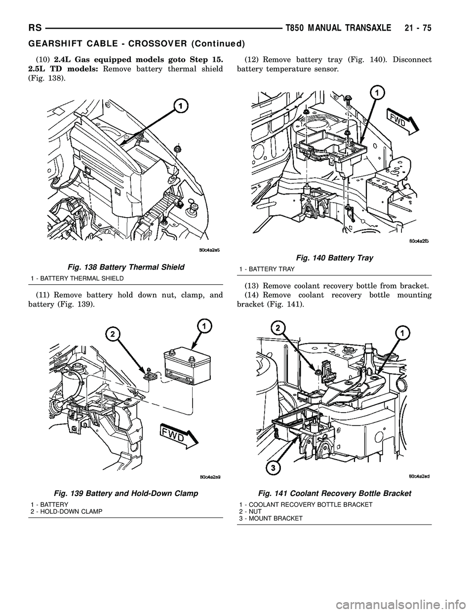
(10)2.4L Gas equipped models goto Step 15.
2.5L TD models:Remove battery thermal shield
(Fig. 138).
(11) Remove battery hold down nut, clamp, and
battery (Fig. 139).(12) Remove battery tray (Fig. 140). Disconnect
battery temperature sensor.
(13) Remove coolant recovery bottle from bracket.
(14) Remove coolant recovery bottle mounting
bracket (Fig. 141).
Fig. 138 Battery Thermal Shield
1 - BATTERY THERMAL SHIELD
Fig. 139 Battery and Hold-Down Clamp
1 - BATTERY
2 - HOLD-DOWN CLAMP
Fig. 140 Battery Tray
1 - BATTERY TRAY
Fig. 141 Coolant Recovery Bottle Bracket
1 - COOLANT RECOVERY BOTTLE BRACKET
2 - NUT
3 - MOUNT BRACKET
RST850 MANUAL TRANSAXLE21-75
GEARSHIFT CABLE - CROSSOVER (Continued)
Page 1673 of 2585
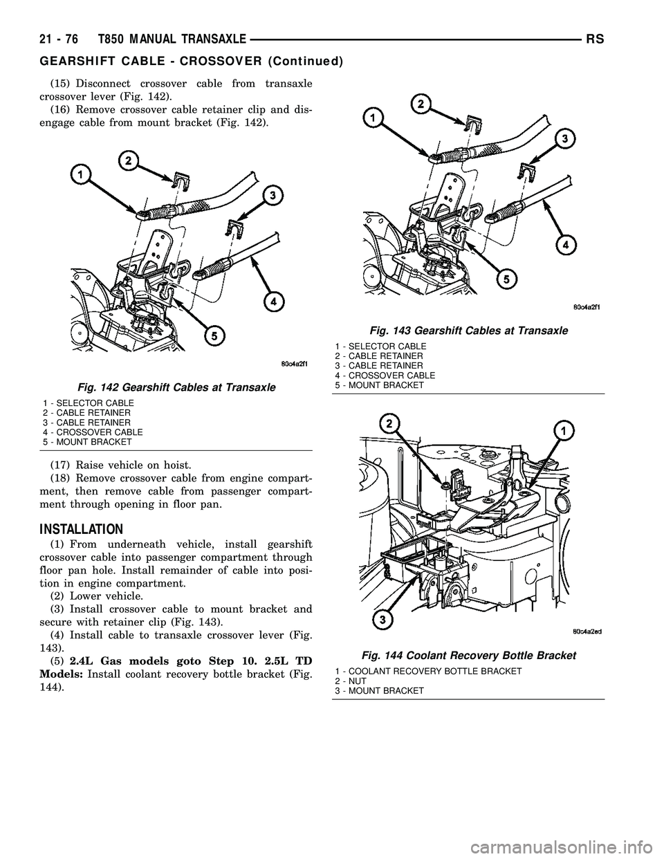
(15) Disconnect crossover cable from transaxle
crossover lever (Fig. 142).
(16) Remove crossover cable retainer clip and dis-
engage cable from mount bracket (Fig. 142).
(17) Raise vehicle on hoist.
(18) Remove crossover cable from engine compart-
ment, then remove cable from passenger compart-
ment through opening in floor pan.
INSTALLATION
(1) From underneath vehicle, install gearshift
crossover cable into passenger compartment through
floor pan hole. Install remainder of cable into posi-
tion in engine compartment.
(2) Lower vehicle.
(3) Install crossover cable to mount bracket and
secure with retainer clip (Fig. 143).
(4) Install cable to transaxle crossover lever (Fig.
143).
(5)2.4L Gas models goto Step 10. 2.5L TD
Models:Install coolant recovery bottle bracket (Fig.
144).
Fig. 142 Gearshift Cables at Transaxle
1 - SELECTOR CABLE
2 - CABLE RETAINER
3 - CABLE RETAINER
4 - CROSSOVER CABLE
5 - MOUNT BRACKET
Fig. 143 Gearshift Cables at Transaxle
1 - SELECTOR CABLE
2 - CABLE RETAINER
3 - CABLE RETAINER
4 - CROSSOVER CABLE
5 - MOUNT BRACKET
Fig. 144 Coolant Recovery Bottle Bracket
1 - COOLANT RECOVERY BOTTLE BRACKET
2 - NUT
3 - MOUNT BRACKET
21 - 76 T850 MANUAL TRANSAXLERS
GEARSHIFT CABLE - CROSSOVER (Continued)
Page 1681 of 2585
(17) Raise vehicle on hoist.
(18) Remove selector cable from engine compart-
ment, then remove cable from passenger compart-
ment through opening in floor pan.
INSTALLATION
(1) From underneath vehicle, install gearshift
selector cable into passenger compartment through
floor pan hole. Install remainder of cable into posi-
tion in engine compartment.
(2) Lower vehicle.
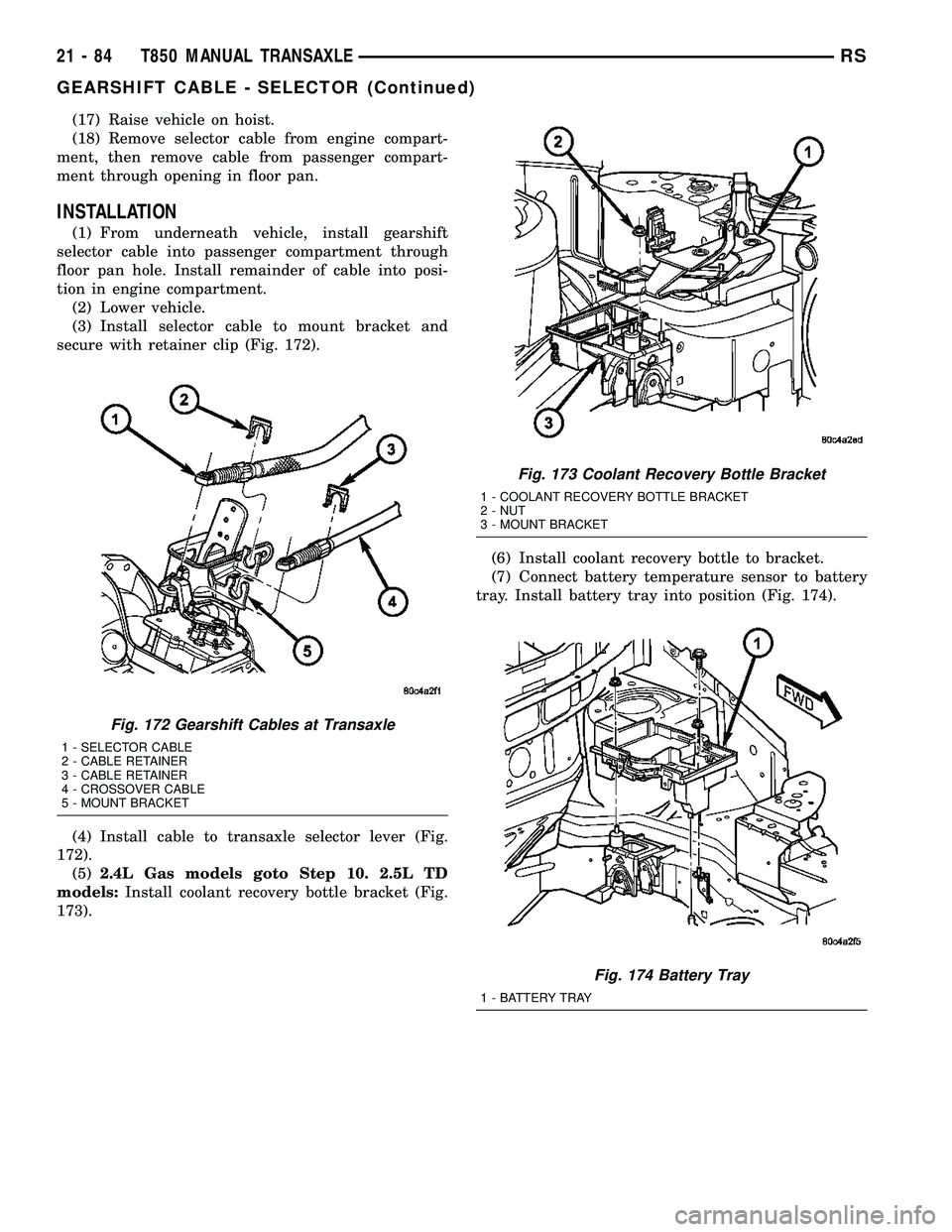
(3) Install selector cable to mount bracket and
secure with retainer clip (Fig. 172).
(4) Install cable to transaxle selector lever (Fig.
172).
(5)2.4L Gas models goto Step 10. 2.5L TD
models:Install coolant recovery bottle bracket (Fig.
173).(6) Install coolant recovery bottle to bracket.
(7) Connect battery temperature sensor to battery
tray. Install battery tray into position (Fig. 174).
Fig. 172 Gearshift Cables at Transaxle
1 - SELECTOR CABLE
2 - CABLE RETAINER
3 - CABLE RETAINER
4 - CROSSOVER CABLE
5 - MOUNT BRACKET
Fig. 173 Coolant Recovery Bottle Bracket
1 - COOLANT RECOVERY BOTTLE BRACKET
2 - NUT
3 - MOUNT BRACKET
Fig. 174 Battery Tray
1 - BATTERY TRAY
21 - 84 T850 MANUAL TRANSAXLERS
GEARSHIFT CABLE - SELECTOR (Continued)
Page 1787 of 2585
Moving the switch up causes an upshift and moving
the switch down causes a downshift. The instrument
cluster will illuminate the selected gear. The vehicle
can be launched in 1st, 2nd, or 3rd gear while in the
Autostick mode. The speed control is operable in 3rd
and 4th gear Autostick mode. Speed control will be
deactivated if the transaxle is shifted to 2nd gear.
Shifting into OD position cancels the Autostick mode,
and the transaxle resumes the OD shift schedule.
DRIVING CLUTCHES
DESCRIPTION
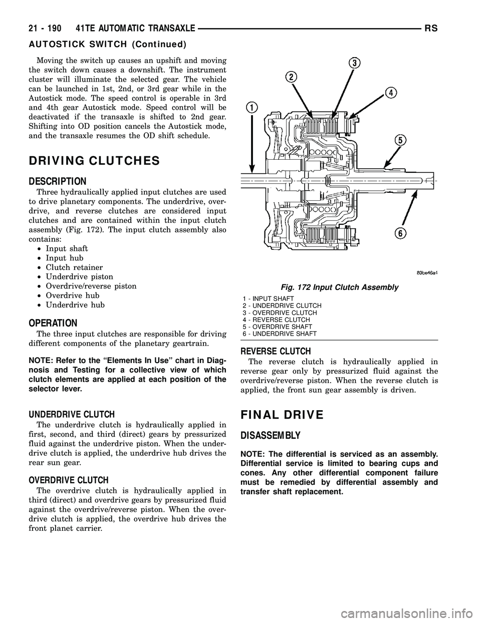
Three hydraulically applied input clutches are used
to drive planetary components. The underdrive, over-
drive, and reverse clutches are considered input
clutches and are contained within the input clutch
assembly (Fig. 172). The input clutch assembly also
contains:
²Input shaft
²Input hub
²Clutch retainer
²Underdrive piston
²Overdrive/reverse piston
²Overdrive hub
²Underdrive hub
OPERATION
The three input clutches are responsible for driving
different components of the planetary geartrain.
NOTE: Refer to the ªElements In Useº chart in Diag-
nosis and Testing for a collective view of which
clutch elements are applied at each position of the
selector lever.
UNDERDRIVE CLUTCH
The underdrive clutch is hydraulically applied in
first, second, and third (direct) gears by pressurized
fluid against the underdrive piston. When the under-
drive clutch is applied, the underdrive hub drives the
rear sun gear.
OVERDRIVE CLUTCH
The overdrive clutch is hydraulically applied in
third (direct) and overdrive gears by pressurized fluid
against the overdrive/reverse piston. When the over-
drive clutch is applied, the overdrive hub drives the
front planet carrier.
REVERSE CLUTCH
The reverse clutch is hydraulically applied in
reverse gear only by pressurized fluid against the
overdrive/reverse piston. When the reverse clutch is
applied, the front sun gear assembly is driven.
FINAL DRIVE
DISASSEMBLY
NOTE: The differential is serviced as an assembly.
Differential service is limited to bearing cups and
cones. Any other differential component failure
must be remedied by differential assembly and
transfer shaft replacement.
Fig. 172 Input Clutch Assembly
1 - INPUT SHAFT
2 - UNDERDRIVE CLUTCH
3 - OVERDRIVE CLUTCH
4 - REVERSE CLUTCH
5 - OVERDRIVE SHAFT
6 - UNDERDRIVE SHAFT
21 - 190 41TE AUTOMATIC TRANSAXLERS
AUTOSTICK SWITCH (Continued)
Page 1820 of 2585
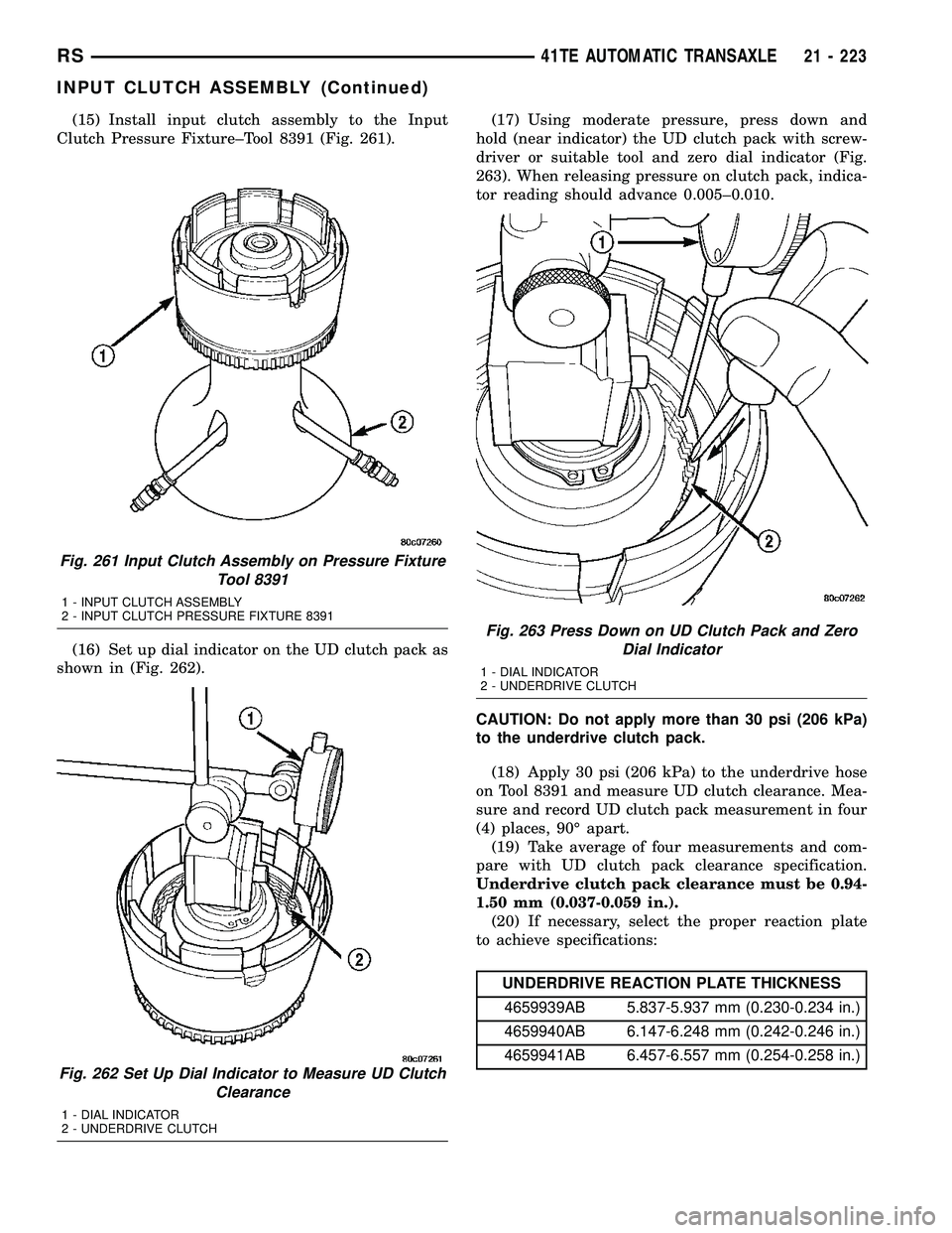
(15) Install input clutch assembly to the Input
Clutch Pressure Fixture±Tool 8391 (Fig. 261).
(16) Set up dial indicator on the UD clutch pack as
shown in (Fig. 262).(17) Using moderate pressure, press down and
hold (near indicator) the UD clutch pack with screw-
driver or suitable tool and zero dial indicator (Fig.
263). When releasing pressure on clutch pack, indica-
tor reading should advance 0.005±0.010.
CAUTION: Do not apply more than 30 psi (206 kPa)
to the underdrive clutch pack.
(18) Apply 30 psi (206 kPa) to the underdrive hose
on Tool 8391 and measure UD clutch clearance. Mea-
sure and record UD clutch pack measurement in four
(4) places, 90É apart.
(19) Take average of four measurements and com-
pare with UD clutch pack clearance specification.
Underdrive clutch pack clearance must be 0.94-
1.50 mm (0.037-0.059 in.).
(20) If necessary, select the proper reaction plate
to achieve specifications:
UNDERDRIVE REACTION PLATE THICKNESS
4659939AB 5.837-5.937 mm (0.230-0.234 in.)
4659940AB 6.147-6.248 mm (0.242-0.246 in.)
4659941AB 6.457-6.557 mm (0.254-0.258 in.)
Fig. 261 Input Clutch Assembly on Pressure Fixture
Tool 8391
1 - INPUT CLUTCH ASSEMBLY
2 - INPUT CLUTCH PRESSURE FIXTURE 8391
Fig. 262 Set Up Dial Indicator to Measure UD Clutch
Clearance
1 - DIAL INDICATOR
2 - UNDERDRIVE CLUTCH
Fig. 263 Press Down on UD Clutch Pack and Zero
Dial Indicator
1 - DIAL INDICATOR
2 - UNDERDRIVE CLUTCH
RS41TE AUTOMATIC TRANSAXLE21 - 223
INPUT CLUTCH ASSEMBLY (Continued)
Page 1825 of 2585
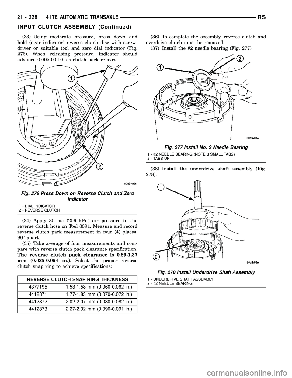
(33) Using moderate pressure, press down and
hold (near indicator) reverse clutch disc with screw-
driver or suitable tool and zero dial indicator (Fig.
276). When releasing pressure, indicator should
advance 0.005-0.010. as clutch pack relaxes.
(34) Apply 30 psi (206 kPa) air pressure to the
reverse clutch hose on Tool 8391. Measure and record
reverse clutch pack measurement in four (4) places,
90É apart.
(35) Take average of four measurements and com-
pare with reverse clutch pack clearance specification.
The reverse clutch pack clearance is 0.89-1.37
mm (0.035-0.054 in.).Select the proper reverse
clutch snap ring to achieve specifications:
REVERSE CLUTCH SNAP RING THICKNESS
4377195 1.53-1.58 mm (0.060-0.062 in.)
4412871 1.77-1.83 mm (0.070-0.072 in.)
4412872 2.02-2.07 mm (0.080-0.082 in.)
4412873 2.27-2.32 mm (0.090-0.091 in.)(36) To complete the assembly, reverse clutch and
overdrive clutch must be removed.
(37) Install the #2 needle bearing (Fig. 277).
(38) Install the underdrive shaft assembly (Fig.
278).
Fig. 276 Press Down on Reverse Clutch and Zero
Indicator
1 - DIAL INDICATOR
2 - REVERSE CLUTCH
Fig. 277 Install No. 2 Needle Bearing
1 - #2 NEEDLE BEARING (NOTE 3 SMALL TABS)
2 - TABS UP
Fig. 278 Install Underdrive Shaft Assembly
1 - UNDERDRIVE SHAFT ASSEMBLY
2 - #2 NEEDLE BEARING
21 - 228 41TE AUTOMATIC TRANSAXLERS
INPUT CLUTCH ASSEMBLY (Continued)