2004 CHRYSLER VOYAGER fuse diagram
[x] Cancel search: fuse diagramPage 1535 of 2585
(3) Disconnect injector wiring connector from injec-
tor.
(4) Position fuel rail assembly so that the fuel
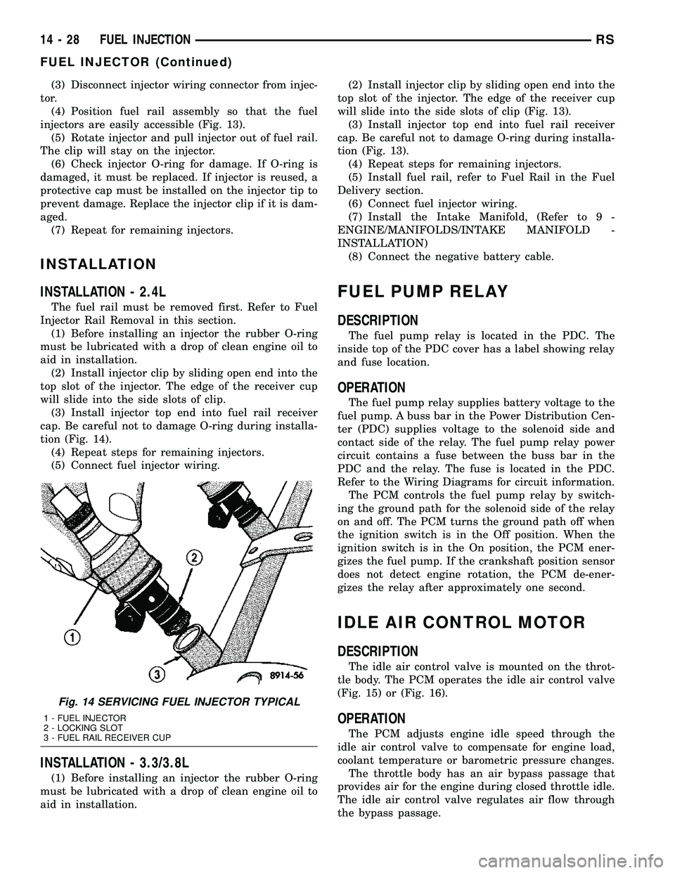
injectors are easily accessible (Fig. 13).
(5) Rotate injector and pull injector out of fuel rail.
The clip will stay on the injector.
(6) Check injector O-ring for damage. If O-ring is
damaged, it must be replaced. If injector is reused, a
protective cap must be installed on the injector tip to
prevent damage. Replace the injector clip if it is dam-
aged.
(7) Repeat for remaining injectors.
INSTALLATION
INSTALLATION - 2.4L
The fuel rail must be removed first. Refer to Fuel
Injector Rail Removal in this section.
(1) Before installing an injector the rubber O-ring
must be lubricated with a drop of clean engine oil to
aid in installation.
(2) Install injector clip by sliding open end into the
top slot of the injector. The edge of the receiver cup
will slide into the side slots of clip.
(3) Install injector top end into fuel rail receiver
cap. Be careful not to damage O-ring during installa-
tion (Fig. 14).
(4) Repeat steps for remaining injectors.
(5) Connect fuel injector wiring.
INSTALLATION - 3.3/3.8L
(1) Before installing an injector the rubber O-ring
must be lubricated with a drop of clean engine oil to
aid in installation.(2) Install injector clip by sliding open end into the
top slot of the injector. The edge of the receiver cup
will slide into the side slots of clip (Fig. 13).
(3) Install injector top end into fuel rail receiver
cap. Be careful not to damage O-ring during installa-
tion (Fig. 13).
(4) Repeat steps for remaining injectors.
(5) Install fuel rail, refer to Fuel Rail in the Fuel
Delivery section.
(6) Connect fuel injector wiring.
(7) Install the Intake Manifold, (Refer to 9 -
ENGINE/MANIFOLDS/INTAKE MANIFOLD -
INSTALLATION)
(8) Connect the negative battery cable.
FUEL PUMP RELAY
DESCRIPTION
The fuel pump relay is located in the PDC. The
inside top of the PDC cover has a label showing relay
and fuse location.
OPERATION
The fuel pump relay supplies battery voltage to the
fuel pump. A buss bar in the Power Distribution Cen-
ter (PDC) supplies voltage to the solenoid side and
contact side of the relay. The fuel pump relay power
circuit contains a fuse between the buss bar in the
PDC and the relay. The fuse is located in the PDC.
Refer to the Wiring Diagrams for circuit information.
The PCM controls the fuel pump relay by switch-
ing the ground path for the solenoid side of the relay
on and off. The PCM turns the ground path off when
the ignition switch is in the Off position. When the
ignition switch is in the On position, the PCM ener-
gizes the fuel pump. If the crankshaft position sensor
does not detect engine rotation, the PCM de-ener-
gizes the relay after approximately one second.
IDLE AIR CONTROL MOTOR
DESCRIPTION
The idle air control valve is mounted on the throt-
tle body. The PCM operates the idle air control valve
(Fig. 15) or (Fig. 16).
OPERATION
The PCM adjusts engine idle speed through the
idle air control valve to compensate for engine load,
coolant temperature or barometric pressure changes.
The throttle body has an air bypass passage that
provides air for the engine during closed throttle idle.
The idle air control valve regulates air flow through
the bypass passage.
Fig. 14 SERVICING FUEL INJECTOR TYPICAL
1 - FUEL INJECTOR
2 - LOCKING SLOT
3 - FUEL RAIL RECEIVER CUP
14 - 28 FUEL INJECTIONRS
FUEL INJECTOR (Continued)
Page 2415 of 2585
²The normally open terminal (87) provides a bat-
tery current output to the compressor clutch coil
through the compressor clutch relay output circuit
only when the compressor clutch relay coil is ener-
gized.
²The normally closed terminal (87A) is not con-
nected to any circuit in this application, but provides
a battery current output only when the compressor
clutch relay coil is de-energized.
The A/C compressor clutch relay cannot be
repaired and, if faulty or damaged, it must be
replaced. Refer to the appropriate wiring information
for diagnosis and testing of the micro-relay and for
complete HVAC wiring diagrams.
REMOVAL
(1) Disconnect and isolate the negative battery
cable.
(2) Remove the cover from the integrated power
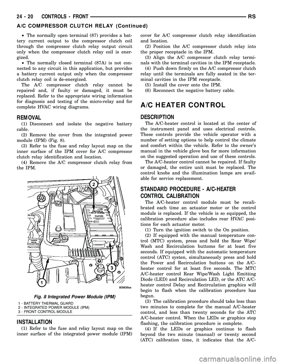
module (IPM) (Fig. 8).
(3) Refer to the fuse and relay layout map on the
inner surface of the IPM cover for A/C compressor
clutch relay identification and location.
(4) Remove the A/C compressor clutch relay from
the IPM.
INSTALLATION
(1) Refer to the fuse and relay layout map on the
inner surface of the integrated power module (IPM)cover for A/C compressor clutch relay identification
and location.
(2) Position the A/C compressor clutch relay into
the proper receptacle in the IPM.
(3) Align the A/C compressor clutch relay termi-
nals with the terminal cavities in the IPM receptacle.
(4) Push down firmly on the A/C compressor clutch
relay until the terminals are fully seated in the ter-
minal cavities in the IPM receptacle.
(5) Install the cover onto the IPM.
(6) Reconnect the negative battery cable.
A/C HEATER CONTROL
DESCRIPTION
The A/C-heater control is located at the center of
the instrument panel and uses electrical controls.
These controls provide the vehicle operator with a
number of setting options to help control the climate
and comfort within the vehicle. Refer to the owner's
manual in the vehicle glove box for more information
on the suggested operation and use of these controls.
The A/C-heater control cannot be repaired. If faulty
or damaged, the entire unit must be replaced. The
control knobs and the illumination lamps are avail-
able for service replacement.
STANDARD PROCEDURE - A/C-HEATER
CONTROL CALIBRATION
The A/C-heater control module must be recali-
brated each time an actuator motor or the control
module is replaced. If the vehicle is so equipped, the
calibration procedure also includes rear HVAC posi-
tions for each actuator motor.
(1) Turn the ignition switch to the On position.
(2) If equipped with the manual temperature con-
trol (MTC) system, press and hold the Rear Wipe/
Wash and Recirculation buttoms for at least five
seconds. If equipped with the automatic temperature
control (ATC) systen, simultaneously press and hold
the Power and Recirculation buttons on the A/C-
heater control for at least five seconds. The MTC
A/C-heater control Rear Wipe/Wash Light Emitting
Diode (LED) and Recirculation LED, or the ATC A/C-
heater control Delay and Recirculation graphics will
begin to flash when the calibration procedure has
begun.
(3) The calibration procedure should take less than
two minutes to complete for the manual A/C-heater
control, and less than twenty seconds for the ATC
A/C-heater control. When the LEDs or graphics stop
flashing, the calibration procedure is complete.
(4) If the LEDs or graphics continue to flash
beyond the two minute (manual) or twenty second
(ATC) calibration time, it indicates that the A/C-
Fig. 8 Integrated Power Module (IPM)
1 - BATTERY THERMAL GUARD
2 - INTEGRATED POWER MODULE (IPM)
3 - FRONT CONTROL MODULE
24 - 20 CONTROLS - FRONTRS
A/C COMPRESSOR CLUTCH RELAY (Continued)
Page 2420 of 2585
normally open contact point. When the relay coil is
de-energized, spring pressure returns the movable
contact point back against the fixed normally closed
contact point. The resistor or diode is connected in
parallel with the relay coil in the relay, and helps to
dissipate voltage spikes and electromagnetic interfer-
ence that can be generated as the electromagnetic
field of the relay coil collapses.
The blower motor relay terminals are connected to
the vehicle electrical system through a receptacle in
the Integrated Power Module (IPM). The inputs and
outputs of the blower motor relay include:
²The common feed terminal (30) receives a bat-
tery current input from the battery through a B(+)
circuit at all times.
²The coil ground terminal (85) receives a ground
input through the front/rear blower motor relay con-
trol circuit only when the FCM electronically pulls
the control circuit to ground.
²The coil battery terminal (86) receives a battery
current input from the battery through a B(+) circuit
at all times.
²The normally open terminal (87) provides a bat-
tery current output to the blower motor resistor
(manual heater-A/C control) or blower power module
(automatic heater-A/C control) through a fuse in the
IPM on the fused front blower motor relay output cir-
cuit only when the blower motor relay coil is ener-
gized.
²The normally closed terminal (87A) is not con-
nected to any circuit in this application, but provides
a battery current output only when the blower motor
relay coil is de-energized.
Refer to the appropriate wiring information for
diagnosis and testing of the micro-relay and for com-
plete HVAC wiring diagrams.
REMOVAL
(1) Disconnect and isolate the battery negative
cable.
(2) Unlatch and remove the cover from the Inte-
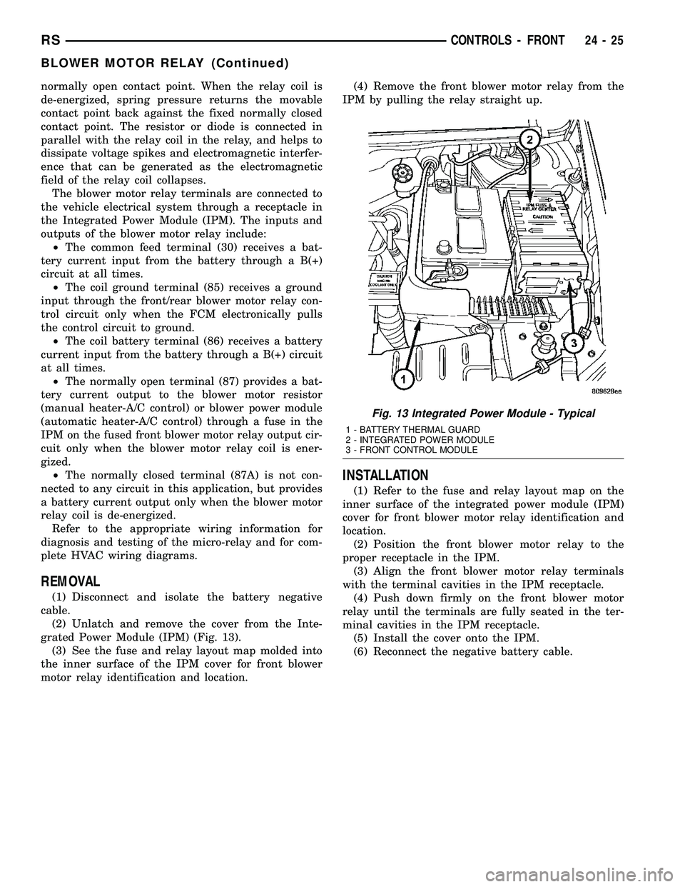
grated Power Module (IPM) (Fig. 13).
(3) See the fuse and relay layout map molded into
the inner surface of the IPM cover for front blower
motor relay identification and location.(4) Remove the front blower motor relay from the
IPM by pulling the relay straight up.
INSTALLATION
(1) Refer to the fuse and relay layout map on the
inner surface of the integrated power module (IPM)
cover for front blower motor relay identification and
location.
(2) Position the front blower motor relay to the
proper receptacle in the IPM.
(3) Align the front blower motor relay terminals
with the terminal cavities in the IPM receptacle.
(4) Push down firmly on the front blower motor
relay until the terminals are fully seated in the ter-
minal cavities in the IPM receptacle.
(5) Install the cover onto the IPM.
(6) Reconnect the negative battery cable.
Fig. 13 Integrated Power Module - Typical
1 - BATTERY THERMAL GUARD
2 - INTEGRATED POWER MODULE
3 - FRONT CONTROL MODULE
RSCONTROLS - FRONT24-25
BLOWER MOTOR RELAY (Continued)
Page 2433 of 2585
Refer to the appropriate wiring information for
diagnosis and testing of the micro-relay and for com-
plete HVAC wiring diagrams.
REMOVAL
(1) Disconnect and isolate the battery negative
cable.
(2) Unlatch and remove the cover from the Inte-
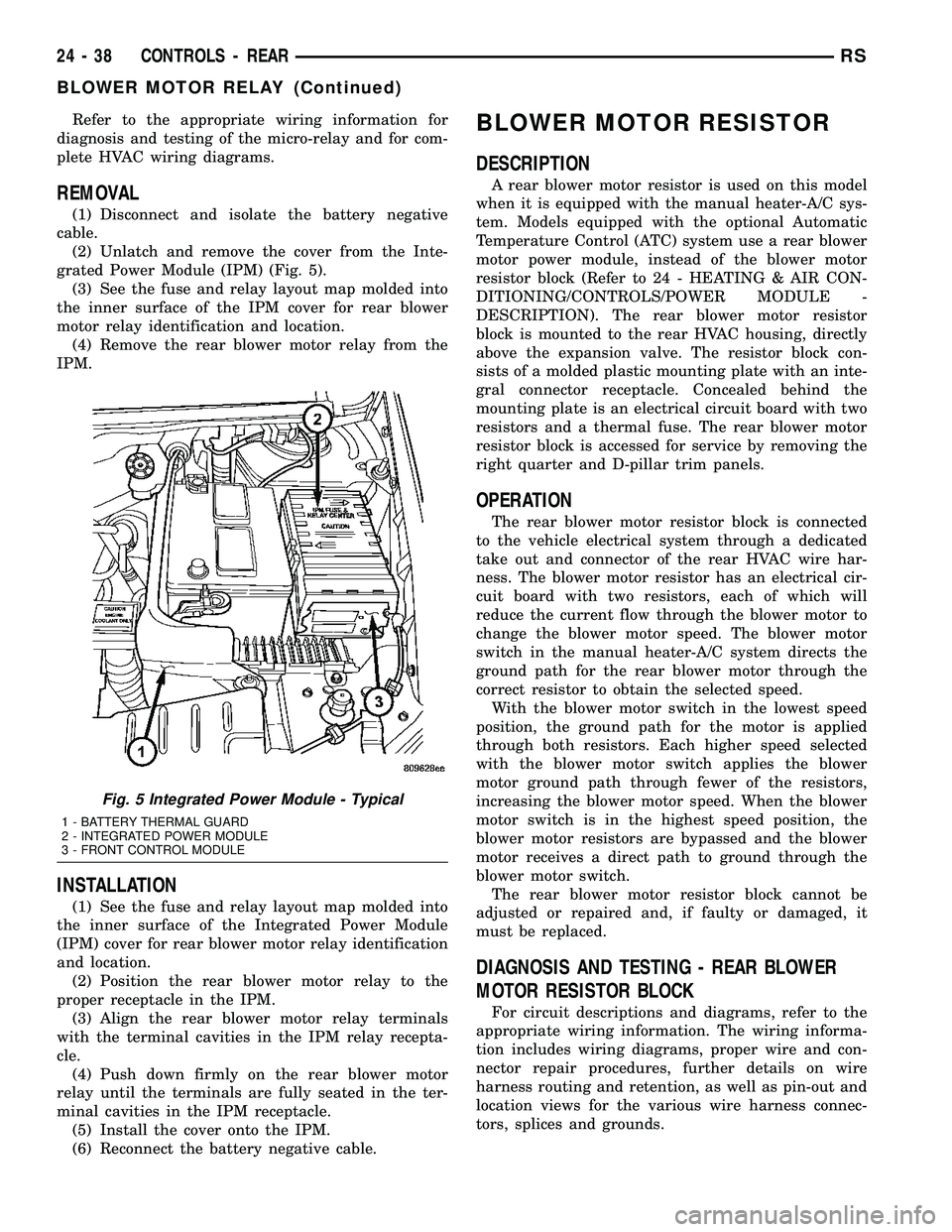
grated Power Module (IPM) (Fig. 5).
(3) See the fuse and relay layout map molded into
the inner surface of the IPM cover for rear blower
motor relay identification and location.
(4) Remove the rear blower motor relay from the
IPM.
INSTALLATION
(1) See the fuse and relay layout map molded into
the inner surface of the Integrated Power Module
(IPM) cover for rear blower motor relay identification
and location.
(2) Position the rear blower motor relay to the
proper receptacle in the IPM.
(3) Align the rear blower motor relay terminals
with the terminal cavities in the IPM relay recepta-
cle.
(4) Push down firmly on the rear blower motor
relay until the terminals are fully seated in the ter-
minal cavities in the IPM receptacle.
(5) Install the cover onto the IPM.
(6) Reconnect the battery negative cable.
BLOWER MOTOR RESISTOR
DESCRIPTION
A rear blower motor resistor is used on this model
when it is equipped with the manual heater-A/C sys-
tem. Models equipped with the optional Automatic
Temperature Control (ATC) system use a rear blower
motor power module, instead of the blower motor
resistor block (Refer to 24 - HEATING & AIR CON-
DITIONING/CONTROLS/POWER MODULE -
DESCRIPTION). The rear blower motor resistor
block is mounted to the rear HVAC housing, directly
above the expansion valve. The resistor block con-
sists of a molded plastic mounting plate with an inte-
gral connector receptacle. Concealed behind the
mounting plate is an electrical circuit board with two
resistors and a thermal fuse. The rear blower motor
resistor block is accessed for service by removing the
right quarter and D-pillar trim panels.
OPERATION
The rear blower motor resistor block is connected
to the vehicle electrical system through a dedicated
take out and connector of the rear HVAC wire har-
ness. The blower motor resistor has an electrical cir-
cuit board with two resistors, each of which will
reduce the current flow through the blower motor to
change the blower motor speed. The blower motor
switch in the manual heater-A/C system directs the
ground path for the rear blower motor through the
correct resistor to obtain the selected speed.
With the blower motor switch in the lowest speed
position, the ground path for the motor is applied
through both resistors. Each higher speed selected
with the blower motor switch applies the blower
motor ground path through fewer of the resistors,
increasing the blower motor speed. When the blower
motor switch is in the highest speed position, the
blower motor resistors are bypassed and the blower
motor receives a direct path to ground through the
blower motor switch.
The rear blower motor resistor block cannot be
adjusted or repaired and, if faulty or damaged, it
must be replaced.
DIAGNOSIS AND TESTING - REAR BLOWER
MOTOR RESISTOR BLOCK
For circuit descriptions and diagrams, refer to the
appropriate wiring information. The wiring informa-
tion includes wiring diagrams, proper wire and con-
nector repair procedures, further details on wire
harness routing and retention, as well as pin-out and
location views for the various wire harness connec-
tors, splices and grounds.
Fig. 5 Integrated Power Module - Typical
1 - BATTERY THERMAL GUARD
2 - INTEGRATED POWER MODULE
3 - FRONT CONTROL MODULE
24 - 38 CONTROLS - REARRS
BLOWER MOTOR RELAY (Continued)
Page 2442 of 2585
blower motor to regulate the blower motor ground
path it provides. The blower motor and wheel are
used to control the velocity of air moving through the
HVAC housing by spinning the blower wheel within
the housing at the selected speed or, in the ATC sys-
tem, at the selected or programmed speed.
DIAGNOSIS AND TESTING - BLOWER MOTOR
BLOWER MOTOR INOPERATIVE
WARNING: ON VEHICLES EQUIPPED WITH AIR-
BAGS, DISABLE THE AIRBAG SYSTEM BEFORE
ATTEMPTING ANY STEERING WHEEL, STEERING
COLUMN, OR INSTRUMENT PANEL COMPONENT
DIAGNOSIS OR SERVICE. DISCONNECT AND ISO-
LATE THE BATTERY NEGATIVE (GROUND) CABLE,
THEN WAIT TWO MINUTES FOR THE AIRBAG SYS-
TEM CAPACITOR TO DISCHARGE BEFORE PER-
FORMING FURTHER DIAGNOSIS OR SERVICE. THIS
IS THE ONLY SURE WAY TO DISABLE THE AIRBAG
SYSTEM. FAILURE TO TAKE THE PROPER PRE-
CAUTIONS COULD RESULT IN ACCIDENTAL AIR-
BAG DEPLOYMENT AND POSSIBLE PERSONAL
INJURY.
For circuit descriptions and diagrams, refer to the
appropriate wiring information. The wiring informa-
tion includes wiring, diagrams, proper wire and con-
nector repair procedures, further details on wire
harness routing and retention, as well as pin-out and
location views for the various wire harness connec-
tors, splices and grounds.
BLOWER MOTOR ELECTRICAL DIAGNOSIS
(1) Check the fuse (Fuse 10 - 40 ampere) in the
Integrated Power Module (IPM). If OK, go to Step 2.
If not OK, repair the shorted circuit or component as
required and replace the faulty fuse.
(2) Turn the ignition switch to the On position. Be
certain that the A/C-heater control power is turned
on. Check for battery voltage at the fuse (Fuse 10 -
40 ampere) in the IPM. If OK, go to Step 3. If not
OK, check the front blower motor relay.
(3) Turn the ignition switch to the Off position.
Disconnect and isolate the battery negative cable.
Disconnect the front HVAC wire harness connector
for the front blower motor resistor block (Manual
Temperature Control) or the front blower motor
power module (Automatic Temperature Control) from
the resistor or module connector receptacle. Recon-
nect the battery negative cable. Turn the ignition
switch to the On position. Be certain that the A/C-
heater control power is turned on. Check for battery
voltage at the fused front blower motor relay output
circuit cavity of the front HVAC wire harness connec-
tor for the front blower motor resistor block (MTC) orthe front blower motor power module (ATC). If OK,
go to Step 4. If not OK, repair the open fused front
blower motor relay output circuit to the IPM as
required.
(4) Turn the ignition switch to the Off position.
Disconnect and isolate the battery negative cable.
Disconnect the front blower motor pigtail wire con-
nector from the connector receptacle of the front
blower motor resistor block (MTC) or the front
blower motor power module (ATC). Use jumper wires
to connect a battery and ground feeds to the blower
motor pigtail wire connector. The blower motor
should operate. If OK with MTC, proceed to diagno-
sis of the front blower motor resistor block (Refer to
24 - HEATING & AIR CONDITIONING/CONTROLS
- FRONT/BLOWER MOTOR RESISTOR - DIAGNO-
SIS AND TESTING). If OK with ATC, use a DRBIII
scan tool to diagnose the front blower motor power
module. Refer to Body Diagnostic information. If not
OK with MTC or ATC, replace the faulty front blower
motor.
BLOWER MOTOR NOISE OR VIBRATION
Refer to the Blower Motor Noise/Vibration Diagno-
sis chart for basic checks of the blower motor when a
vibration or noise is present (Fig. 7).
REMOVAL
WARNING: ON VEHICLES EQUIPPED WITH AIR-
BAGS, DISABLE THE AIRBAG SYSTEM BEFORE
ATTEMPTING ANY STEERING WHEEL, STEERING
COLUMN, OR INSTRUMENT PANEL COMPONENT
DIAGNOSIS OR SERVICE. DISCONNECT AND ISO-
LATE THE BATTERY NEGATIVE (GROUND) CABLE,
THEN WAIT TWO MINUTES FOR THE AIRBAG SYS-
TEM CAPACITOR TO DISCHARGE BEFORE PER-
FORMING FURTHER DIAGNOSIS OR SERVICE. THIS
IS THE ONLY SURE WAY TO DISABLE THE AIRBAG
SYSTEM. FAILURE TO TAKE THE PROPER PRE-
CAUTIONS COULD RESULT IN AN ACCIDENTAL
AIRBAG DEPLOYMENT AND POSSIBLE PERSONAL
INJURY.
NOTE: The blower motor is located on the passen-
ger side of the vehicle under the instrument panel.
The blower motor can be removed from the vehicle
without having to remove the HVAC housing.
(1) Disconnect and isolate the battery negative
cable.
(2) Remove the passenger side door sill plate and
cowl panel.
(3) Pull back the carpet to access the front lower
air intake screw.
RSDISTRIBUTION - FRONT24-47
BLOWER MOTOR (Continued)
Page 2453 of 2585
DIAGNOSIS AND TESTING - REAR BLOWER
MOTOR
BLOWER MOTOR INOPERATIVE
For circuit descriptions and diagrams, refer to the
appropriate wiring information. The wiring informa-
tion includes wiring, diagrams, proper wire and con-
nector repair procedures, further details on wire
harness routing and retention, as well as pin-out and
location views for the various wire harness connec-
tors, splices and grounds.
BLOWER MOTOR ELECTRICAL DIAGNOSIS
(1) Check the fuse (Fuse 12 - 25 ampere) in the
Integrated Power Module (IPM). If OK, go to Step 2.
If not OK, repair the shorted circuit or component as
required and replace the faulty fuse.
(2) Turn the ignition switch to the On position. Be
certain that the rear A/C-heater control power is
turned on. Check for battery voltage at the fuse
(Fuse 12 - 25 ampere) in the IPM. If OK, go to Step
3. If not OK, check the rear blower motor relay.
(3) Turn the ignition switch to the Off position.
Disconnect and isolate the battery negative cable.
Disconnect the rear HVAC wire harness connector
from the rear blower motor resistor block (Manual
Temperature Control) or the rear blower motor power
module (Automatic Temperature Control). Reconnect
the battery negative cable. Turn the ignition switch
to the On position. Be certain that the rear A/C-
heater control power is turned on. Check for battery
voltage at the fused rear blower motor relay output
circuit cavity of the rear HVAC wire harness connec-
tor for the rear blower motor resistor block (MTC) or
the rear blower motor power module (ATC). If OK, go
to Step 4. If not OK, repair the open fused front
blower motor relay output circuit to the IPM as
required.
(4) Turn the ignition switch to the Off position.
Disconnect and isolate the battery negative cable.
Disconnect the rear blower motor pigtail wire connec-
tor from the rear HVAC wire harness (MTC) or the
rear blower power module (ATC). Use jumper wires
to connect a battery and ground feeds to the blower
motor pigtail wire connector. The rear blower motor
should operate. If OK with MTC, proceed to diagno-
sis of the rear blower motor resistor block (Refer to
24 - HEATING & AIR CONDITIONING/CONTROLS
- REAR/BLOWER MOTOR RESISTOR - DIAGNOSIS
AND TESTING). If OK with ATC, use a DRBIII scan
tool to diagnose the rear blower motor power module.
Refer to the appropriate diagnostic information. If
not OK with MTC or ATC, replace the faulty rear
blower motor.BLOWER MOTOR NOISE OR VIBRATION
Refer to the Blower Motor Noise/Vibration Diagno-
sis chart for basic checks of the blower motor when a
vibration or noise is present (Fig. 3).
REMOVAL
WARNING: REFER TO THE APPLICABLE WARN-
INGS AND CAUTIONS FOR THIS SYSTEM BEFORE
PERFORMING THE FOLLOWING OPERATION (Refer
to 24 - HEATING & AIR CONDITIONING/PLUMBING -
WARNING) and (Refer to 24 - HEATING & AIR CON-
DITIONING/PLUMBING - CAUTION).
(1) Remove the rear HVAC housing from the vehi-
cle (Refer to 24 - HEATING & AIR CONDITIONING/
DISTRIBUTION/HVAC HOUSING - REMOVAL).
(2) Disconnect the rear blower motor pigtail wire
connector.
NOTE: With the Manual Temperature Control sys-
tem, the blower motor pigtail wire is connected to a
take out and connector of the rear HVAC wire har-
ness. With the Automatic Temperature Control sys-
tem , the blower pigtail wire is connected to a
receptacle on the blower motor power module.
(3) Remove the three screws that secure the rear
blower motor to the outboard side of the rear HVAC
housing (Fig. 4).
(4) Remove the rear blower motor from the rear
HVAC housing.
INSTALLATION
(1) Position the rear blower motor into the rear
HVAC housing.
(2) Install the three screws that secure the blower
motor to the rear HVAC housing. Tighten the screws
to 2 N´m (17 in. lbs.).
(3) Reconnect the rear blower motor pigtail wire
connector.
NOTE: With the Manual Temperature Control system
, the blower pigtail wire is connected to a take out
and connector of the rear HVAC wire harness. With
the Automatic Temperature Control system, the
blower pigtail wire is connected to a receptacle on
the blower motor power module.
24 - 58 DISTRIBUTION - REARRS
BLOWER MOTOR (Continued)
Page 2579 of 2585
TIMING CHAIN COVER - INSTALLATION . . . 9-155
TIMING CHAIN COVER - REMOVAL......9-153
TIMING CHAIN WEAR - STANDARD
PROCEDURE, MEASURING.............9-153
TIMING VERIFICATION - STANDARD
PROCEDURE, VALVE..................9-153
TIRE - DESCRIPTION.............22-13,22s-5
TIRE AND WHEEL ASSEMBLY
(ALUMINUM WHEEL) - INSTALLATION.....22-8
TIRE AND WHEEL ASSEMBLY
(ALUMINUM WHEEL) - REMOVAL........22-7
TIRE AND WHEEL ASSEMBLY (STEEL
WHEEL) - INSTALLATION...............22-8
TIRE AND WHEEL ASSEMBLY (STEEL
WHEEL) - REMOVAL...................22-8
TIRE AND WHEEL BALANCE -
STANDARD PROCEDURE................22-5
TIRE AND WHEEL MATCH MOUNTING -
STANDARD PROCEDURE................22-7
TIRE AND WHEEL ROTATION -
STANDARD PROCEDURE................22-7
TIRE AND WHEEL VIBRATION -
DIAGNOSIS AND TESTING..............22-1
TIRE INFLATION PRESSURES -
STANDARD PROCEDURE..........22-16,22s-8
TIRE LEAK REPAIRING - STANDARD
PROCEDURE...................22-17,22s-9
TIRE NOISE - DIAGNOSIS AND TESTING . . 22-14,
22s-6
TIRE PRESSURE FOR HIGH SPEED
OPERATION - STANDARD PROCEDURE . . . 22-17,
22s-9
TIRE PRESSURE MONITORING -
DESCRIPTION...................22-9,22s-1
TIRE PRESSURE MONITORING -
OPERATION.....................22-9,22s-1
TIRE PRESSURE SENSOR - DIAGNOSIS
AND TESTING..................22-10,22s-2
TIRE PRESSURE SENSOR RETRAIN -
STANDARD PROCEDURE..........22-10,22s-2
TIRE (TEMPORARY) - DESCRIPTION,
SPARE ........................22-14,22s-6
TIRE WEAR PATTERNS - DIAGNOSIS
AND TESTING..................22-16,22s-8
TIRES - CLEANING.............22-17,22s-10
TIRES - DESCRIPTION, RADIAL-PLY . 22-14,22s-6
TIRES - DESCRIPTION, REPLACEMENT . . . 22-14,
22s-6
TIRE/VEHICLE LEAD - DIAGNOSIS AND
TESTING......................22-14,22s-6
TO CYLINDER BORE FITTING -
STANDARD PROCEDURE, PISTON........9-42
TO FILLER NECK SEAL - DIAGNOSIS
AND TESTING, RADIATOR CAP...........7-27
TO GROUND - STANDARD PROCEDURE,
TESTING FOR A SHORT.............8W-01-9
TO GROUND ON FUSES POWERING
SEVERAL LOADS - STANDARD
PROCEDURE, TESTING FOR A SHORT . 8W-01-10
TO USE WIRING DIAGRAMS -
DESCRIPTION, HOW................8W-01-1
TONE WHEEL - INSPECTION.............5-82
TONE WHEEL RUNOUT, SPECIFICATIONS . . . 5-79
TOOLS - 2.4L ENGINE, SPECIAL..........9-21
TOOLS - 3.3/3.8L ENGINE, SPECIAL.......9-95
TOOLS - 41TE AUTOMATIC TRANSAXLE,
SPECIAL..........................21-183
TOOLS - BASE BRAKE SYSTEM, SPECIAL . . 5-10,
5s-9
TOOLS - BATTERY SYSTEM SPECIAL
TOOLS, SPECIAL......................8F-7
TOOLS - BODY, SPECIAL...............23-13
TOOLS - COOLING SYSTEM, SPECIAL......7-6
TOOLS - EXHAUST SYSTEM, SPECIAL.....11-4
TOOLS - FRONT SUSPENSION, SPECIAL....2-3
TOOLS - FUEL, SPECIAL...........14-23,14-4
TOOLS - OVERHEAD CONSOLE, SPECIAL . . 8M-6
TOOLS - POWER DISTRIBUTION
SYSTEMS, SPECIAL................8W-97-1
TOOLS - POWER STEERING GEAR,
SPECIAL...........................19-34
TOOLS - POWER STEERING PUMP,
SPECIAL
...........................19-43
TOOLS - POWER STEERING, SPECIAL
.....19-9
TOOLS - REAR SUSPENSION, SPECIAL
....2-28
TOOLS - SDP POWER TRANSFER UNIT,
SPECIAL
............................21-8
TOOLS - WIRING/TERMINAL, SPECIAL
. 8W-01-10TOOLS, DIAGNOSIS AND TESTING -
SPECIAL............................3-34
TOOLS, SCHEMATICS AND DIAGRAMS -
SPECIAL...........................21s-89
TOOLS, SPECIAL TOOLS - BATTERY
SYSTEM SPECIAL.....................8F-7
TOOLS, SPECIFICATIONS - SPECIAL......8F-23
TOOLS, T850 TRANSAXLE - SPECIAL.......6-6
TOOLS, T850 TRANSAXLE - SPECIAL.....21-58
TOP COVER - INSTALLATION,
INSTRUMENT PANEL..................23-69
TOP COVER - REMOVAL, INSTRUMENT
PANEL.............................23-68
TOP PAD ASSEMBLY - INSTALLATION,
INSTRUMENT PANEL..................23-72
TOP PAD ASSEMBLY - REMOVAL,
INSTRUMENT PANEL..................23-71
TORQUES, SPECIFICATIONS.......8F-33,8F-35
TOUCH-UP - DESCRIPTION, PAINTED.....23-85
TOWING - STANDARD PROCEDURE.......0-29
TPM - CAUTION, SENSOR.........22-10,22s-2
TPM - DESCRIPTION, SENSOR.....22-10,22s-1
TPM - INSTALLATION, SENSOR....22-12,22s-3
TPM - OPERATION, SENSOR.......22-10,22s-2
TPM - REMOVAL, SENSOR........22-11,22s-2
TRACK - DESCRIPTION, DRIVER POWER
SEAT.........................8N-15,8N-58
TRACK - DESCRIPTION, PASSENGER
POWER SEAT..................8N-16,8N-59
TRACK - DIAGNOSIS AND TESTING,
DRIVER POWER SEAT...........8N-15,8N-58
TRACK - DIAGNOSIS AND TESTING,
POWER SEAT..................8N-17,8N-60
TRACK - INSTALLATION, BENCH SEAT . . . 23-104
TRACK - INSTALLATION, DRIVER POWER
SEAT.........................8N-16,8N-59
TRACK - INSTALLATION, FRONT SEAT
RISER - MANUAL....................23-95
TRACK - INSTALLATION, PASSENGER
POWER SEAT..................8N-18,8N-61
TRACK - OPERATION, DRIVER POWER
SEAT.........................8N-15,8N-58
TRACK - OPERATION, PASSENGER
POWER SEAT..................8N-17,8N-60
TRACK & RACK - DESCRIPTION, LOWER
DRIVE UNIT........................8N-34
TRACK & RACK - INSTALLATION,
LOWER DRIVE UNIT..................8N-34
TRACK & RACK - OPERATION, LOWER
DRIVE UNIT........................8N-34
TRACK & RACK - REMOVAL, LOWER
DRIVE UNIT........................8N-34
TRACK - REAR COVER - INSTALLATION,
FRONT SEAT........................23-96
TRACK - REAR COVER - REMOVAL,
FRONT SEAT........................23-96
TRACK - REMOVAL, BENCH SEAT.......23-104
TRACK - REMOVAL, DRIVER POWER
SEAT.........................8N-16,8N-59
TRACK - REMOVAL, FRONT SEAT RISER
- MANUAL..........................23-94
TRACK - REMOVAL, PASSENGER POWER
SEAT.........................8N-18,8N-61
TRACK BAR - DESCRIPTION.............2-46
TRACK BAR - INSTALLATION............2-46
TRACK BAR - OPERATION...............2-46
TRACK BAR - REMOVAL................2-46
TRACK MANUAL ADJUSTER -
INSTALLATION, FRONT SEAT...........23-95
TRACK MANUAL ADJUSTER - REMOVAL,
FRONT SEAT........................23-95
TRACK POWER ADJUSTER -
INSTALLATION, FRONT SEAT...........23-95
TRACK POWER ADJUSTER - REMOVAL,
FRONT SEAT........................23-95
TRACTION CONTROL SWITCH -
DIAGNOSIS AND TESTING..............5-82
TRACTION CONTROL SYSTEM -
DESCRIPTION........................5-76
TRACTION CONTROL SYSTEM -
OPERATION
..........................5-77
TRANSAXLE - ASSEMBLY, 41TE
AUTOMATIC
.......................21s-184
TRANSAXLE - ASSEMBLY, T850 MANUAL
. 21-42
TRANSAXLE - DESCRIPTION, 40TE
AUTOMATIC
........................21s-25
TRANSAXLE - DESCRIPTION, 41TE
AUTOMATIC
........................21-117TRANSAXLE - DESCRIPTION, T850
MANUAL...........................21-21
TRANSAXLE - DISASSEMBLY, 41TE
AUTOMATIC.......................21s-166
TRANSAXLE - DISASSEMBLY, T850
MANUAL...........................21-35
TRANSAXLE - INSTALLATION, T850
MANUAL...........................21-51
TRANSAXLE - OPERATION, 40TE
AUTOMATIC........................21s-27
TRANSAXLE - OPERATION, 41TE
AUTOMATIC........................21-119
TRANSAXLE - OPERATION, T850
MANUAL...........................21-24
TRANSAXLE - REMOVAL, T850 MANUAL . . 21-31
TRANSAXLE - SPECIAL TOOLS, T850.......6-6
TRANSAXLE - SPECIAL TOOLS, T850.....21-58
TRANSAXLE - SPECIFICATIONS, 41TE . . . 21-181,
21s-87
TRANSAXLE - SPECIFICATIONS, T850
MANUAL...........................21-56
TRANSAXLE FLUID - DESCRIPTION,
AUTOMATIC/MANUAL...................0-4
TRANSAXLE GENERAL DIAGNOSIS -
DIAGNOSIS AND TESTING, 41TE.......21-119
TRANSAXLE GENERAL DIAGNOSIS -
DIAGNOSIS AND TESTING, 4XTE.......21s-27
TRANSAXLE HYDRAULIC SCHEMATICS,
SCHEMATICS AND DIAGRAMS - 41TE . . . 21-169
TRANSAXLE HYDRAULIC SCHEMATICS,
SCHEMATICS AND DIAGRAMS - 4XTE . . . 21s-75
TRANSAXLE, SPECIAL TOOLS - 41TE
AUTOMATIC.........................21-183
TRANSDUCER - DESCRIPTION, A/C
PRESSURE.........................24-21
TRANSDUCER - DIAGNOSIS AND
TESTING, A/C PRESSURE..............24-22
TRANSDUCER - INSTALLATION, A/C
PRESSURE.........................24-22
TRANSDUCER - OPERATION, A/C
PRESSURE.........................24-21
TRANSDUCER - REMOVAL, A/C
PRESSURE.........................24-22
TRANSFER UNIT - DESCRIPTION,
POWER.............................21-1
TRANSFER UNIT - OPERATION, POWER....21-3
TRANSFER UNIT FLUID - DESCRIPTION,
AWD POWER..........................0-6
TRANSFER UNIT, SPECIAL TOOLS - SDP
POWER.............................21-8
TRANSMISSION CONTROL MODULE -
DESCRIPTION.......................8E-20
TRANSMISSION CONTROL MODULE -
OPERATION.........................8E-20
TRANSMISSION CONTROL RELAY -
DESCRIPTION...............21-247,21s-150
TRANSMISSION CONTROL RELAY -
OPERATION.................21-248,21s-150
TRANSMISSION OIL COOLER -
DESCRIPTION........................7-37
TRANSMISSION OIL COOLER -
INSPECTION.........................7-37
TRANSMISSION OIL COOLER -
INSTALLATION........................7-37
TRANSMISSION OIL COOLER -
REMOVAL...........................7-37
TRANSMISSION OIL COOLER LINES -
INSTALLATION........................7-38
TRANSMISSION OIL COOLER LINES -
REMOVAL...........................7-38
TRANSMISSION RANGE SENSOR -
DESCRIPTION...............21-248,21s-150
TRANSMISSION RANGE SENSOR -
INSTALLATION...............21-249,21s-152
TRANSMISSION RANGE SENSOR -
OPERATION.................21-248,21s-151
TRANSMISSION RANGE SENSOR -
REMOVAL..................21-249,21s-151
TRANSMITTER - DESCRIPTION,
UNIVERSAL
........................8M-10
TRANSMITTER - DIAGNOSIS AND
TESTING, KEYLESS ENTRY
........8N-42,8N-5
TRANSMITTER - DIAGNOSIS AND
TESTING, UNIVERSAL
................8M-10
TRANSMITTER - OPERATION,
UNIVERSAL
........................8M-10
TRANSMITTER CODES - STANDARD
PROCEDURE, ERASING
...............8M-11
36 INDEXRS
Description Group-Page Description Group-Page Description Group-Page