2004 CHRYSLER VOYAGER check transmission fluid
[x] Cancel search: check transmission fluidPage 1965 of 2585

STANDARD PROCEDURE - FLUID AND FILTER
SERVICE
NOTE: Refer to the maintenance schedules in
LUBRICATION and MAINTENANCE, or the vehicle
owner's manual, for the recommended maintenance
(fluid/filter change) intervals for this transaxle.
NOTE: Only fluids of the type labeled MoparTATF+4
should be used. A filter change should be made at
the time of the transmission oil change. The magnet
(on the inside of the oil pan) should also be cleaned
with a clean, dry cloth.
NOTE: If the transaxle is disassembled for any rea-
son, the fluid and filter should be changed.
FLUID/FILTER SERVICE (RECOMMENDED)
(1) Raise vehicle on a hoist. Refer to LUBRICA-
TION and MAINTENANCE for proper procedures.
Place a drain container with a large opening, under
transaxle oil pan. (2) Remove both engine mount-to-engine cross-
member cradle nuts. Using suitable screw jack and
wood block, raise engine and transmission slightly to
facilitate transaxle oil pan removal and installation. (3) Loosen pan bolts and tap the pan at one corner
to break it loose allowing fluid to drain, then remove
the oil pan. (4) Install a new filter and o-ring on bottom of the
valve body (Fig. 189). (5) Clean the oil pan and magnet. Reinstall pan
using new Mopar Silicone Adhesive sealant. Tighten
oil pan bolts to 19 N´m (165 in. lbs.). (6) Pour four quarts of Mopar tATF+4 through the
dipstick opening. (7) Start engine and allow to idle for at least one
minute. Then, with parking and service brakes
applied, move selector lever momentarily to each
position, ending in the park or neutral position. (8) Check the transaxle fluid level and add an
appropriate amount to bring the transaxle fluid level
to 3mm (1/8 in.) below the lowest mark on the dip-
stick (Fig. 190).
(9) Recheck the fluid level after the transaxle has
reached normal operating temperature (180ÉF.). Refer
to Fluid Level and Condition Check for the proper
fluid fill procedure. (10) To prevent dirt from entering transaxle, make
certain that dipstick is fully seated into the dipstick
opening.
DIPSTICK TUBE FLUID SUCTION METHOD
(ALTERNATIVE)
(1) When performing the fluid suction method,
make sure the transaxle is at full operating temper-
ature. (2) To perform the dipstick tube fluid suction
method, use a suitable fluid suction device (VaculaŸ
or equivalent). (3) Insert the fluid suction line into the dipstick
tube.
NOTE: Verify that the suction line is inserted to the
lowest point of the transaxle oil pan. This will
ensure complete evacuation of the fluid in the pan.
(4) Follow the manufacturers recommended proce-
dure and evacuate the fluid from the transaxle.
Fig. 189 Filter and O-Ring
1 - OIL FILTER
2 - O-RING
Fig. 190 Fluid Level Indicator
1 - FLUID LEVEL INDICATOR
21s - 104 40TE AUTOMATIC TRANSAXLERS
FLUID (Continued)
Page 1966 of 2585
(5) Remove the suction line from the dipstick tube.
(6) Pour four quarts of MopartATF+4 through the
dipstick opening. (7) Start engine and allow to idle for at least one
minute. Then, with parking and service brakes
applied, move selector lever momentarily to each
position, ending in the park or neutral position. (8) Check the transaxle fluid level and add an
appropriate amount to bring the transaxle fluid level
to 3mm (1/8 in.) below the lowest mark on the dip-
stick (Fig. 190). (9) Recheck the fluid level after the transaxle has
reached normal operating temperature (180ÉF.).
(Refer to 21 - TRANSMISSION/TRANSAXLE/AUTO-
MATIC - 41TE/FLUID - STANDARD PROCEDURE) (10) To prevent dirt from entering transaxle, make
certain that dipstick is fully seated into the dipstick
opening.
GEAR SHIFT CABLE
REMOVAL
(1) Disconnect battery cables.
(2) Remove battery shield.
(3) Remove battery.
(4) Remove speed control servo and position out of
way. (5) Disconnect gear shift cable at manual valve
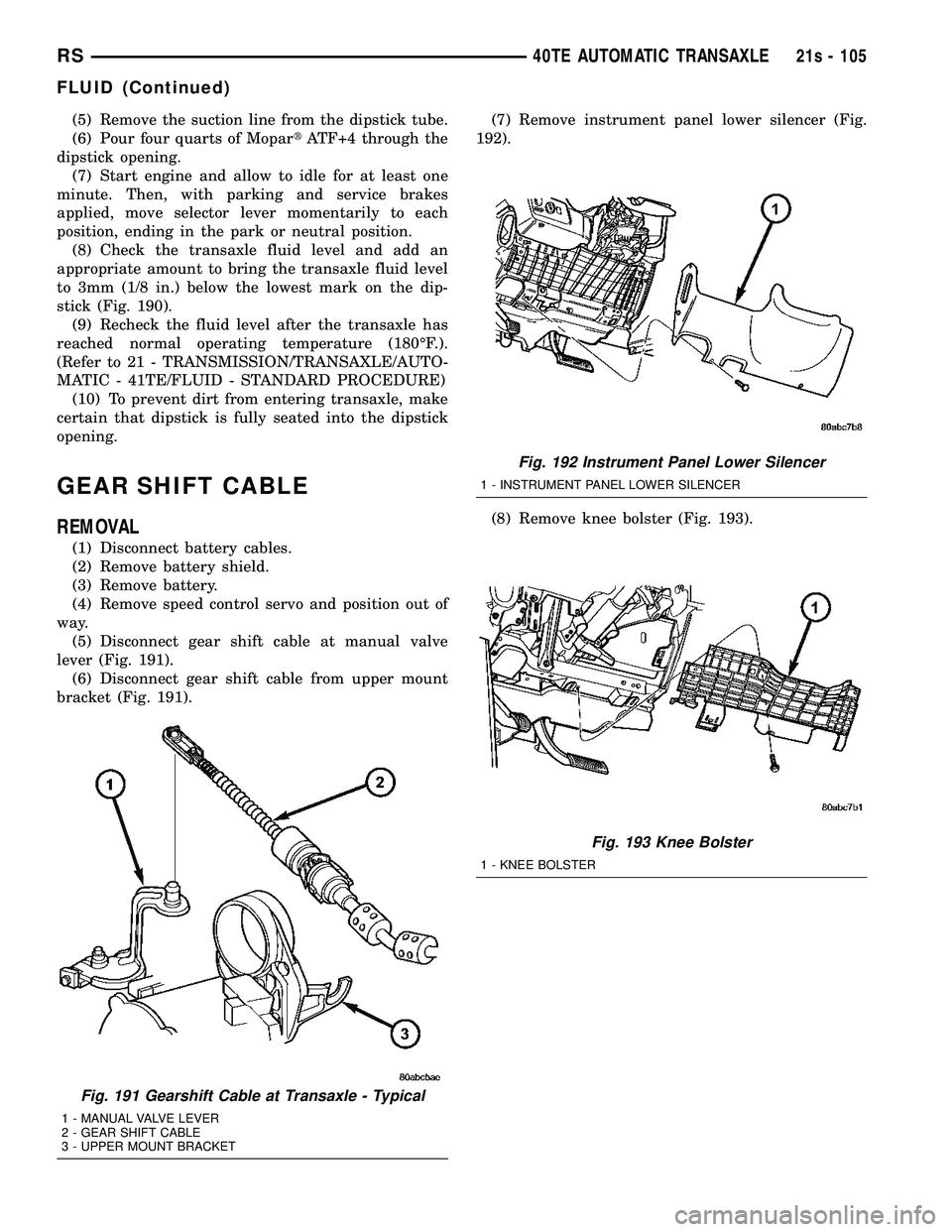
lever (Fig. 191). (6) Disconnect gear shift cable from upper mount
bracket (Fig. 191). (7) Remove instrument panel lower silencer (Fig.
192).
(8) Remove knee bolster (Fig. 193).
Fig. 191 Gearshift Cable at Transaxle - Typical
1 - MANUAL VALVE LEVER
2 - GEAR SHIFT CABLE
3 - UPPER MOUNT BRACKET
Fig. 192 Instrument Panel Lower Silencer
1 - INSTRUMENT PANEL LOWER SILENCER
Fig. 193 Knee Bolster
1 - KNEE BOLSTER
RS 40TE AUTOMATIC TRANSAXLE21s - 105
FLUID (Continued)
Page 2010 of 2585
STATOR
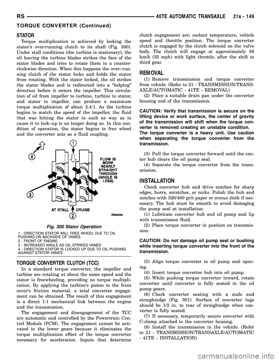
Torque multiplication is achieved by locking the
stator's over-running clutch to its shaft (Fig. 300).
Under stall conditions (the turbine is stationary), the
oil leaving the turbine blades strikes the face of the
stator blades and tries to rotate them in a counter-
clockwise direction. When this happens the over±run-
ning clutch of the stator locks and holds the stator
from rotating. With the stator locked, the oil strikes
the stator blades and is redirected into a ªhelpingº
direction before it enters the impeller. This circula-
tion of oil from impeller to turbine, turbine to stator,
and stator to impeller, can produce a maximum
torque multiplication of about 2.4:1. As the turbine
begins to match the speed of the impeller, the fluid
that was hitting the stator in such as way as to
cause it to lock±up is no longer doing so. In this con-
dition of operation, the stator begins to free wheel
and the converter acts as a fluid coupling.
TORQUE CONVERTER CLUTCH (TCC)
In a standard torque converter, the impeller and
turbine are rotating at about the same speed and the
stator is freewheeling, providing no torque multipli-
cation. By applying the turbine's piston to the front
cover's friction material, a total converter engage-
ment can be obtained. The result of this engagement
is a direct 1:1 mechanical link between the engine
and the transmission. The engagement and disengagement of the TCC
are automatic and controlled by the Powertrain Con-
trol Module (PCM). The engagement cannot be acti-
vated in the lower gears because it eliminates the
torque multiplication effect of the torque converter
necessary for acceleration. Inputs that determine clutch engagement are: coolant temperature, vehicle
speed and throttle position. The torque converter
clutch is engaged by the clutch solenoid on the valve
body. The clutch will engage at approximately 56
km/h (35 mph) with light throttle, after the shift to
third gear.
REMOVAL
(1) Remove transmission and torque converter
from vehicle. (Refer to 21 - TRANSMISSION/TRANS-
AXLE/AUTOMATIC - 41TE - REMOVAL) (2) Place a suitable drain pan under the converter
housing end of the transmission.
CAUTION: Verify that transmission is secure on the
lifting device or work surface, the center of gravity
of the transmission will shift when the torque con-
verter is removed creating an unstable condition.
The torque converter is a heavy unit. Use caution
when separating the torque converter from the
transmission.
(3) Pull the torque converter forward until the cen-
ter hub clears the oil pump seal. (4) Separate the torque converter from the trans-
mission.
INSTALLATION
Check converter hub and drive notches for sharp
edges, burrs, scratches, or nicks. Polish the hub and
notches with 320/400 grit paper or crocus cloth if nec-
essary. The hub must be smooth to avoid damaging
the pump seal at installation. (1) Lubricate converter hub and oil pump seal lip
with transmission fluid. (2) Place torque converter in position on transmis-
sion.
CAUTION: Do not damage oil pump seal or bushing
while inserting torque converter into the front of the
transmission.
(3) Align torque converter to oil pump seal open-
ing. (4) Insert torque converter hub into oil pump.
(5) While pushing torque converter inward, rotate
converter until converter is fully seated in the oil
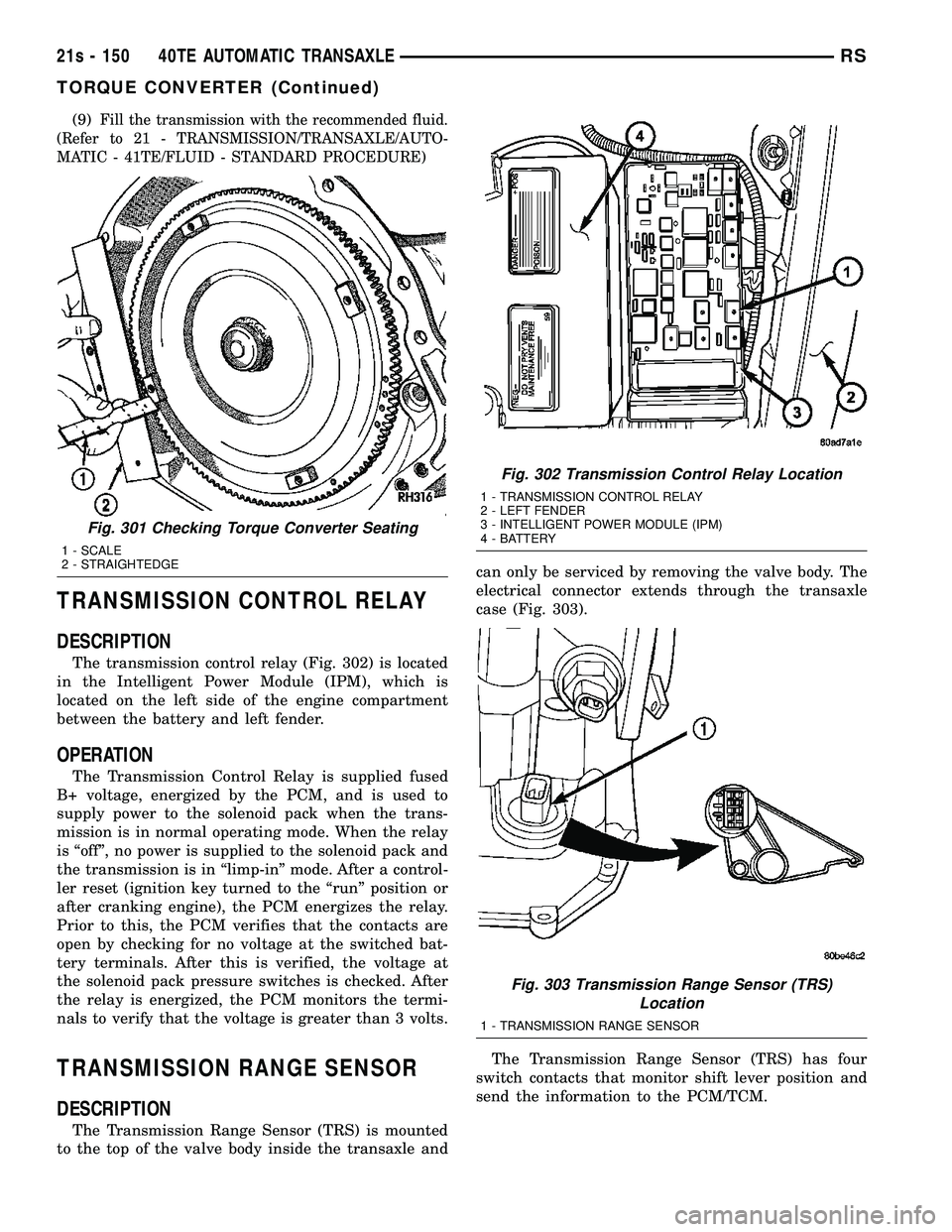
pump gears. (6) Check converter seating with a scale and
straightedge (Fig. 301). Surface of converter lugs
should be 1/2 in. to rear of straightedge when con-
verter is fully seated. (7) If necessary, temporarily secure converter with
C-clamp attached to the converter housing. (8) Install the transmission in the vehicle. (Refer
to 21 - TRANSMISSION/TRANSAXLE/AUTOMATIC
- 41TE - INSTALLATION)
Fig. 300 Stator Operation
1 - DIRECTION STATOR WILL FREE WHEEL DUE TO OIL
PUSHING ON BACKSIDE OF VANES
2 - FRONT OF ENGINE
3 - INCREASED ANGLE AS OIL STRIKES VANES
4 - DIRECTION STATOR IS LOCKED UP DUE TO OIL PUSHING
AGAINST STATOR VANES
RS 40TE AUTOMATIC TRANSAXLE21s - 149
TORQUE CONVERTER (Continued)
Page 2011 of 2585
(9)Fill the transmission with the recommended fluid.
(Refer to 21 - TRANSMISSION/TRANSAXLE/AUTO-
MATIC - 41TE/FLUID - STANDARD PROCEDURE)
TRANSMISSION CONTROL RELAY
DESCRIPTION
The transmission control relay (Fig. 302) is located
in the Intelligent Power Module (IPM), which is
located on the left side of the engine compartment
between the battery and left fender.
OPERATION
The Transmission Control Relay is supplied fused
B+ voltage, energized by the PCM, and is used to
supply power to the solenoid pack when the trans-
mission is in normal operating mode. When the relay
is ªoffº, no power is supplied to the solenoid pack and
the transmission is in ªlimp-inº mode. After a control-
ler reset (ignition key turned to the ªrunº position or
after cranking engine), the PCM energizes the relay.
Prior to this, the PCM verifies that the contacts are
open by checking for no voltage at the switched bat-
tery terminals. After this is verified, the voltage at
the solenoid pack pressure switches is checked. After
the relay is energized, the PCM monitors the termi-
nals to verify that the voltage is greater than 3 volts.
TRANSMISSION RANGE SENSOR
DESCRIPTION
The Transmission Range Sensor (TRS) is mounted
to the top of the valve body inside the transaxle and can only be serviced by removing the valve body. The
electrical connector extends through the transaxle
case (Fig. 303).
The Transmission Range Sensor (TRS) has four
switch contacts that monitor shift lever position and
send the information to the PCM/TCM.
Fig. 301 Checking Torque Converter Seating
1 - SCALE
2 - STRAIGHTEDGE
Fig. 302 Transmission Control Relay Location
1 - TRANSMISSION CONTROL RELAY
2 - LEFT FENDER
3 - INTELLIGENT POWER MODULE (IPM)
4 - BATTERY
Fig. 303 Transmission Range Sensor (TRS) Location
1 - TRANSMISSION RANGE SENSOR
21s - 150 40TE AUTOMATIC TRANSAXLERS
TORQUE CONVERTER (Continued)
Page 2013 of 2585
INSTALLATION
(1) Install transmission range sensor (TRS) to the
valve body and torque retaining screw (Fig. 305) to 5
N´m (45 in. lbs.). (2) Install valve body to transaxle. (Refer to 21 -
TRANSMISSION/TRANSAXLE/AUTOMATIC -
41TE/VALVE BODY - INSTALLATION)
VALVE BODY
DESCRIPTION
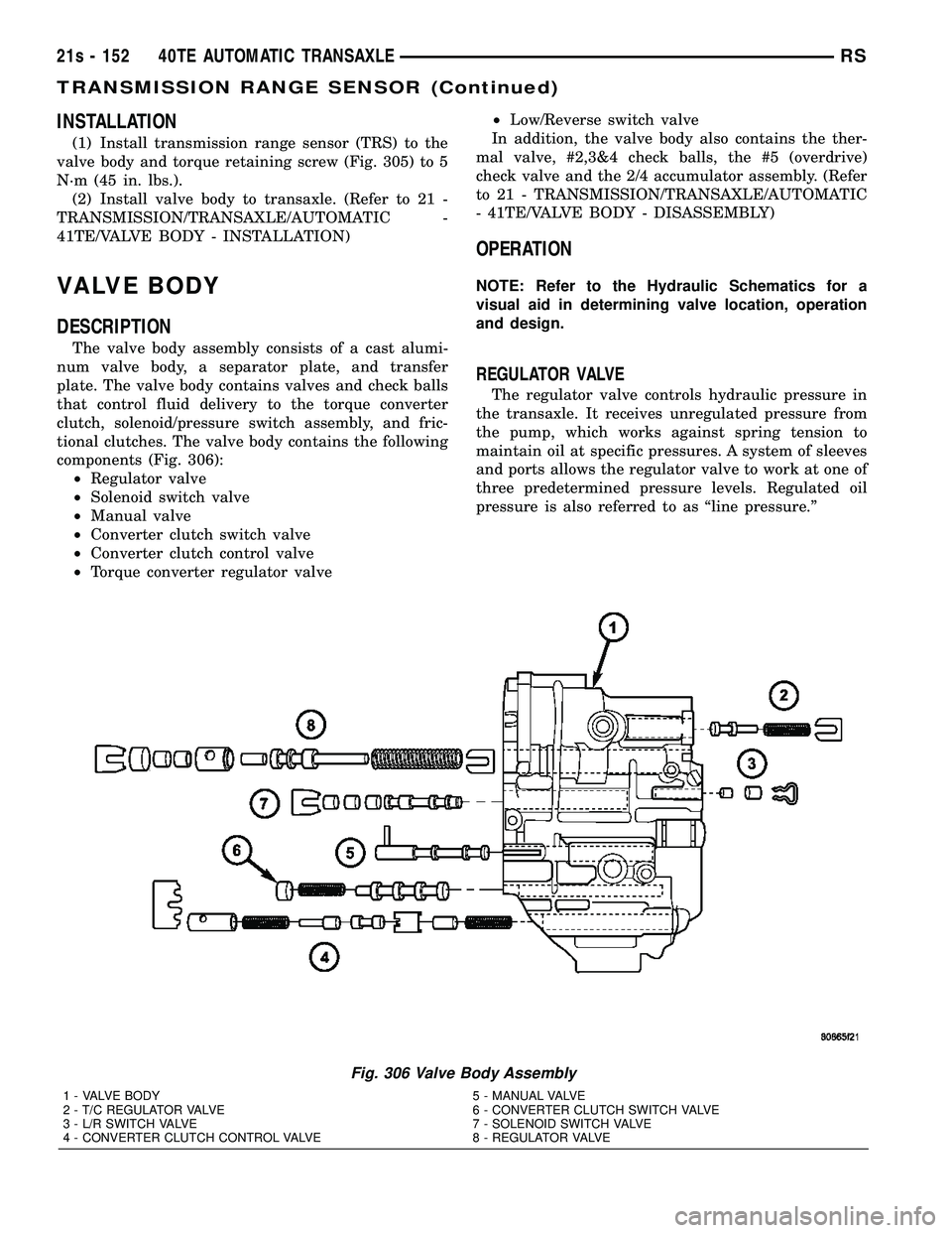
The valve body assembly consists of a cast alumi-
num valve body, a separator plate, and transfer
plate. The valve body contains valves and check balls
that control fluid delivery to the torque converter
clutch, solenoid/pressure switch assembly, and fric-
tional clutches. The valve body contains the following
components (Fig. 306): ² Regulator valve
² Solenoid switch valve
² Manual valve
² Converter clutch switch valve
² Converter clutch control valve
² Torque converter regulator valve ²
Low/Reverse switch valve
In addition, the valve body also contains the ther-
mal valve, #2,3&4 check balls, the #5 (overdrive)
check valve and the 2/4 accumulator assembly. (Refer
to 21 - TRANSMISSION/TRANSAXLE/AUTOMATIC
- 41TE/VALVE BODY - DISASSEMBLY)
OPERATION
NOTE: Refer to the Hydraulic Schematics for a
visual aid in determining valve location, operation
and design.
REGULATOR VALVE
The regulator valve controls hydraulic pressure in
the transaxle. It receives unregulated pressure from
the pump, which works against spring tension to
maintain oil at specific pressures. A system of sleeves
and ports allows the regulator valve to work at one of
three predetermined pressure levels. Regulated oil
pressure is also referred to as ªline pressure.º
Fig. 306 Valve Body Assembly
1 - VALVE BODY 5 - MANUAL VALVE
2 - T/C REGULATOR VALVE 6 - CONVERTER CLUTCH SWITCH VALVE
3 - L/R SWITCH VALVE 7 - SOLENOID SWITCH VALVE
4 - CONVERTER CLUTCH CONTROL VALVE 8 - REGULATOR VALVE
21s - 152 40TE AUTOMATIC TRANSAXLERS
TRANSMISSION RANGE SENSOR (Continued)
Page 2014 of 2585
SOLENOID SWITCH VALVE
The solenoid switch valve controls line pressure
from the LR/CC solenoid. In one position, it allows
the low/reverse clutch to be pressurized. In the other,
it directs line pressure to the converter control and
converter clutch valves.
MANUAL VALVE
The manual valve is operated by the mechanical
shift linkage. Its primary responsibility is to send
line pressure to the appropriate hydraulic circuits
and solenoids. The valve has three operating ranges
or positions.
CONVERTER CLUTCH SWITCH VALVE
The main responsibility of the converter clutch
switch valve is to control hydraulic pressure applied
to the front (off) side of the converter clutch piston.
Line pressure from the regulator valve is fed to the
torque converter regulator valve, where it passes
through the valve, and is slightly regulated. The
pressure is then directed to the converter clutch
switch valve and to the front side of the converter
clutch piston. This pressure pushes the piston back
and disengages the converter clutch.
CONVERTER CLUTCH CONTROL VALVE
The converter clutch control valve controls the
back (on) side of the torque converter clutch. When
the PCM/TCM energizes or modulates the LR/CC
solenoid to apply the converter clutch piston, both
the converter clutch control valve and the converter
control valve move, allowing pressure to be applied to
the back side of the clutch.
T/C REGULATOR VALVE
The torque converter regulator valve slightly regu-
lates the flow of fluid to the torque converter.
LOW/REVERSE SWITCH VALVE
The low/reverse clutch is applied from different
sources, depending on whether low (1st) gear or
reverse is selected. The low/reverse switch valve
alternates positions depending on from which direc-
tion fluid pressure is applied. By design, when the
valve is shifted by fluid pressure from one channel,
the opposing channel is blocked. The switch valve
alienates the possibility of a sticking ball check, thus
providing consistent application of the low/reverse
clutch under all operating conditions.
REMOVAL
NOTE: If valve body is replaced or reconditioned,
the TCM Quick Learn Procedure must be per-
formed. (Refer t o 8 - ELECTRICAL/ELECTRONIC
CONTROL MODULES/TRANSMISSION CONTROL
MODULE - STANDARD PROCEDURE)
(1) Disconnect battery negative cable.
(2) Disconnect gearshift cable from manual valve
lever. (3) Remove manual valve lever from manual shaft.
(4) Raise vehicle on hoist.
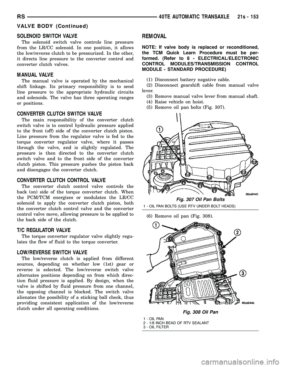
(5) Remove oil pan bolts (Fig. 307).
(6) Remove oil pan (Fig. 308).
Fig. 307 Oil Pan Bolts
1 - OIL PAN BOLTS (USE RTV UNDER BOLT HEADS)
Fig. 308 Oil Pan
1 - OIL PAN
2 - 1/8 INCH BEAD OF RTV SEALANT
3 - OIL FILTER
RS 40TE AUTOMATIC TRANSAXLE21s - 153
VALVE BODY (Continued)
Page 2473 of 2585
INSTALLATION
NOTE: If the A/C condenser is being replaced, add
50 milliliters (1.8 fluid ounce) of refrigerant oil to the
refrigerant system. Use only refrigerant oil of the
type recommended for the compressor in the vehi-
cle.
NOTE: Be certain that each of the radiator and con-
denser air seals are reinstalled in their proper loca-
tions. These air seals are required in order for the
air conditioning and engine cooling systems to per-
form as designed.
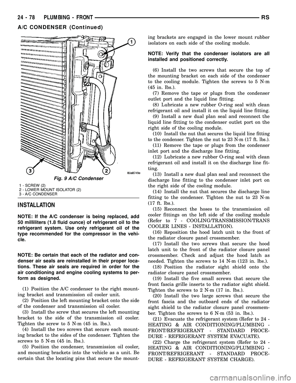
(1) Position the A/C condenser to the right mount-
ing bracket and transmission oil cooler unit.
(2) Position the left mounting bracket onto the side
of the condenser and transmission oil cooler.
(3) Install the screw that secures the left mounting
bracket to the side of the transmission oil cooler.
Tighten the screw to 5 N´m (45 in. lbs.).
(4) Install the two screws that secure each mount-
ing bracket to the sides of the condenser. Tighten the
screws to 5 N´m (45 in. lbs.).
(5) Position the condenser, transmission oil cooler,
and mounting brackets into the vehicle as a unit. Be
certain that the locating pins that secure the mount-ing brackets are engaged in the lower mount rubber
isolators on each side of the cooling module.
NOTE: Verify that the condenser isolators are all
installed and positioned correctly.
(6) Install the two screws that secure the top of
the mounting bracket on each side of the condenser
to the cooling module. Tighten the screws to 5 N´m
(45 in. lbs.).
(7) Remove the tape or plugs from the condenser
outlet port and the liquid line fitting.
(8) Lubricate a new rubber O-ring seal with clean
refrigerant oil and install it on the liquid line fitting.
(9) Install a new dual plan seal and reconnect the
liquid line fitting to the condenser outlet port on the
right side of the cooling module.
(10)
Install the nut that secures the liquid line fitting
to the condenser. Tighten the nut to 23 N´m (17 ft. lbs.).
(11) Remove the tape or plugs from the condenser
inlet port and the discharge line fitting.
(12) Lubricate a new rubber O-ring seal with clean
refrigerant oil and install it on the discharge line fit-
ting.
(13) Install a new dual plan seal and reconnect the
discharge line fitting to the condenser inlet port on
the right side of the cooling module.
(14) Install the nut that secures the discharge line
fitting to the condenser. Tighten the nut to 23 N´m
(17 ft. lbs.).
(15) Reconnect the hoses to the transmission oil
cooler fittings on the left side of the cooling module
(Refer to 7 - COOLING/TRANSMISSION/TRANS
COOLER LINES - INSTALLATION).
(16) Reposition the hood latch unit to the front of
the radiator closure panel crossmember.
(17) Install the two screws that secure the hood
latch unit to the front of the radiator closure panel
crossmember. Check and adjust the hood latch as
needed. Tighten the screws to 14 N´m (123 in. lbs.).
(18) Position the radiator sight shield onto the
radiator closure panel crossmember.
(19) Install the five small screws that secure the
front fascia grille inserts to the radiator sight shield.
Tighten the screws to 2 N´m (17 in. lbs.).
(20) Install the two large screws that secure the
front fascia and the outboard ends of the radiator
sight shield to the radiator closure panel crossmem-
ber. Tighten the screws to 6 N´m (53 in. lbs.).
(21) Evacuate the refrigerant system (Refer to 24 -
HEATING & AIR CONDITIONING/PLUMBING -
FRONT/REFRIGERANT - STANDARD PROCE-
DURE - REFRIGERANT SYSTEM EVACUATE).
(22) Charge the refrigerant system (Refer to 24 -
HEATING & AIR CONDITIONING/PLUMBING -
FRONT/REFRIGERANT - STANDARD PROCE-
DURE - REFRIGERANT SYSTEM CHARGE).
Fig. 9 A/C Condenser
1 - SCREW (2)
2 - LOWER MOUNT ISOLATOR (2)
3 - A/C CONDENSER
24 - 78 PLUMBING - FRONTRS
A/C CONDENSER (Continued)
Page 2548 of 2585
BRAKE CABLE (LEFT REAR) - REMOVAL,
PARKING.......................5-62,5s-64
BRAKE CABLE (RIGHT REAR) -
INSTALLATION, PARKING..........5-63,5s-66
BRAKE CABLE (RIGHT REAR) -
REMOVAL, PARKING..............5-60,5s-63
BRAKE CABLES - ADJUSTMENT,
PARKING.......................5-64,5s-66
BRAKE CALIPER - INSTALLATION, REAR
DISC..........................5-30,5s-29
BRAKE CALIPER - REMOVAL, REAR
DISC..........................5-27,5s-26
BRAKE CALIPER ADAPTER -
INSTALLATION, FRONT DISC........5-31,5s-30
BRAKE CALIPER ADAPTER - REMOVAL,
FRONT DISC....................5-31,5s-30
BRAKE CALIPER (CONTINENTAL TEVES
BRAKES) - INSTALLATION, FRONT
DISC..............................5s-26
BRAKE CALIPER (CONTINENTAL TEVES
BRAKES) - REMOVAL, FRONT DISC......5s-23
BRAKE CALIPER (DISC/DISC BRAKES) -
INSTALLATION, FRONT DISC.............5-27
BRAKE CALIPER (DISC/DISC BRAKES) -
REMOVAL, FRONT DISC................5-24
BRAKE CALIPER (DISC/DRUM BRAKES) -
INSTALLATION, FRONT DISC.............5-27
BRAKE CALIPER (DISC/DRUM BRAKES) -
REMOVAL, FRONT DISC................5-24
BRAKE CALIPER GUIDE PINS (DISC/
DRUM BRAKES) - INSTALLATION, DISC....5-31
BRAKE CALIPER GUIDE PINS (DISC/
DRUM BRAKES) - REMOVAL, DISC.......5-31
BRAKE CALIPER GUIDE PINS (TRW
BRAKES) - INSTALLATION, DISC.........5s-30
BRAKE CALIPER GUIDE PINS (TRW
BRAKES) - REMOVAL, DISC............5s-30
BRAKE CALIPER (TRW BRAKES) -
INSTALLATION, FRONT DISC............5s-26
BRAKE CALIPER (TRW BRAKES) -
REMOVAL, FRONT DISC...............5s-23
BRAKE FASTENER TORQUE,
SPECIFICATIONS...................5-9,5s-8
BRAKE FLUID CONTAMINATION -
DIAGNOSIS AND TESTING.........5-32,5s-31
BRAKE FLUID LEVEL CHECKING -
STANDARD PROCEDURE...........5-32,5s-31
BRAKE FLUID LEVEL SWITCH -
DESCRIPTION....................5-10,5s-9
BRAKE FLUID LEVEL SWITCH -
INSTALLATION...................5-11,5s-10
BRAKE FLUID LEVEL SWITCH -
OPERATION......................5-10,5s-9
BRAKE FLUID LEVEL SWITCH -
REMOVAL......................5-11,5s-10
BRAKE FLUID, SPECIFICATIONS.....5-33,5s-32
BRAKE LAMP SWITCH - DESCRIPTION....8L-4
BRAKE LAMP SWITCH - DIAGNOSIS
AND TESTING........................8L-4
BRAKE LAMP SWITCH - INSTALLATION....8L-5
BRAKE LAMP SWITCH - OPERATION......8L-4
BRAKE LAMP SWITCH - REMOVAL.......8L-5
BRAKE LEVER AND FRONT CABLE -
INSTALLATION, PARKING..........5-66,5s-69
BRAKE LEVER AND FRONT CABLE -
REMOVAL, PARKING
..............5-65,5s-68
BRAKE PROPORTIONING -
DESCRIPTION, ELECTRONIC VARIABLE
....5-75
BRAKE PROPORTIONING - OPERATION,
ELECTRONIC VARIABLE
................5-77
BRAKE ROTOR - DIAGNOSIS AND
TESTING
.......................5-51,5s-54
BRAKE ROTOR - INSTALLATION, FRONT
. . . 5-54,
5s-57
BRAKE ROTOR - REMOVAL, FRONT
. . 5-54,5s-57
BRAKE ROTOR, EXPORT
...........5-55,5s-58
BRAKE ROTOR MACHINING - STANDARD
PROCEDURE
....................5-53,5s-56
BRAKE ROTOR, SPECIFICATIONS
....5-55,5s-57
BRAKE SHOE LINING - INSPECTION,
REAR DRUM
....................5-22,5s-21
BRAKE SHOES - ADJUSTMENT, PARKING
. . 5-73,
5s-76
BRAKE SHOES - ADJUSTMENT, REAR
DRUM
.........................5-23,5s-22
BRAKE SHOES - CLEANING, DISC
....5-16,5-18,
5s-15,5s-17BRAKE SHOES - INSPECTION, DISC . . 5-16,5-18,
5s-15,5s-17
BRAKE SHOES - INSTALLATION, REAR
DISC..........................5-19,5s-18
BRAKE SHOES - INSTALLATION, REAR
DRUM.........................5-22,5s-21
BRAKE SHOES - REMOVAL, REAR DISC . . . 5-17,
5s-16
BRAKE SHOES - REMOVAL, REAR DRUM . . 5-19,
5s-18
BRAKE SHOES (CONTINENTAL TEVES
BRAKES) - INSTALLATION, FRONT
DISC..............................5s-15
BRAKE SHOES (CONTINENTAL TEVES
BRAKES) - REMOVAL, FRONT DISC......5s-14
BRAKE SHOES (DISC/DISC BRAKES) -
INSTALLATION, FRONT DISC.............5-16
BRAKE SHOES (DISC/DISC BRAKES) -
REMOVAL, FRONT DISC................5-14
BRAKE SHOES (DISC/DRUM BRAKES) -
INSTALLATION, FRONT DISC.............5-17
BRAKE SHOES (DISC/DRUM BRAKES) -
REMOVAL, FRONT DISC................5-15
BRAKE SHOES (TRW BRAKES) -
INSTALLATION, FRONT DISC............5s-16
BRAKE SHOES (TRW BRAKES) -
REMOVAL, FRONT DISC...............5s-14
BRAKE SYSTEM - DESCRIPTION,
ANTILOCK...........................5-75
BRAKE SYSTEM - DIAGNOSIS AND
TESTING, BASE....................5-4,5s-4
BRAKE SYSTEM - OPERATION,
ANTILOCK...........................5-76
BRAKE SYSTEM BLEEDING - STANDARD
PROCEDURE, ANTILOCK................5-78
BRAKE SYSTEM (EXPORT) -
DESCRIPTION, ANTILOCK...............5-75
BRAKE SYSTEM, SPECIAL TOOLS - BASE . . 5-10,
5s-9
BRAKE TUBES AND HOSES -
DESCRIPTION...................5-14,5s-13
BRAKE TUBES AND HOSES -
INSPECTION....................5-14,5s-13
BRAKE TUBES AND HOSES - OPERATION . . 5-14,
5s-13
BRAKES - DESCRIPTION, BASE.......5-3,5s-3
BRAKES - OPERATION, BASE.........5-3,5s-3
BRAKES (EXPORT) - DESCRIPTION,
BASE............................5-3,5s-3
BRAKES (EXPORT) - DESCRIPTION, DISC . . 5-13,
5s-12
BRAKES (FRONT) - DESCRIPTION, DISC . . . 5-11,
5s-10
BRAKES (FRONT) - OPERATION, DISC.....5-13,
5s-12
BRAKES (REAR) - DESCRIPTION, DISC....5-12,
5s-12
BRAKES (REAR) - DESCRIPTION, DRUM . . . 5-13,
5s-12
BRAKES (REAR) - OPERATION, DISC . 5-13,5s-13
BRAKE/TRANSMISSION SHIFT
INTERLOCK SOLENOID - DIAGNOSIS
AND TESTING...............21-235,21s-135
BUCKET - INSTALLATION, BUCKET SEAT
BACK - QUAD.......................23-99
BUCKET - INSTALLATION, SEAT BELT
BUCKLE - FIRST ROW INBOARD -
QUAD.............................8O-12
BUCKET - REMOVAL, BUCKET SEAT
BACK - QUAD.......................23-98
BUCKET - REMOVAL, SEAT BELT BUCKLE
- FIRST ROW INBOARD - QUAD.........8O-12
BUCKET, 50/50 SPLIT, BENCH -
INSTALLATION, SEAT BACK HINGE
COVERS - QUAD....................23-101
BUCKET, 50/50 SPLIT, BENCH -
INSTALLATION, SEAT CUSHION COVER
- QUAD
...........................23-100
BUCKET, 50/50 SPLIT, BENCH -
REMOVAL, SEAT BACK HINGE COVERS
- QUAD
...........................23-101
BUCKET, 50/50 SPLIT, BENCH -
REMOVAL, SEAT CUSHION COVER -
QUAD
.............................23-100
BUCKET SEAT BACK - QUAD BUCKET -
INSTALLATION
.......................23-99
BUCKET SEAT BACK - QUAD BUCKET -
REMOVAL
..........................23-98BUCKET SEAT RISER - INSTALLATION,
QUAD..............................23-98
BUCKET SEAT RISER - REMOVAL, QUAD . . 23-98
BUCKET SEAT SIDE SHIELD - NO
CUPHOLDER - INSTALLATION, QUAD.....23-97
BUCKET SEAT SIDE SHIELD - NO
CUPHOLDER - REMOVAL, QUAD........23-97
BUCKET SEAT SIDE SHIELD/CUPHOLDER
- FLAP AND SPRING ASSEMBLY -
INSTALLATION, QUAD................23-107
BUCKET SEAT SIDE SHIELD/CUPHOLDER
- FLAP AND SPRING ASSEMBLY -
REMOVAL, QUAD....................23-107
BUCKET SEAT SIDE SHIELD/CUPHOLDER
- INSTALLATION, QUAD................23-96
BUCKET SEAT SIDE SHIELD/CUPHOLDER
- REMOVAL, QUAD...................23-96
BUCKLE - FIRST ROW - BENCH -
INSTALLATION, SEAT BELT.............8O-13
BUCKLE - FIRST ROW - BENCH -
REMOVAL, SEAT BELT................8O-13
BUCKLE - FIRST ROW INBOARD - QUAD
BUCKET - INSTALLATION, SEAT BELT....8O-12
BUCKLE - FIRST ROW INBOARD - QUAD
BUCKET - REMOVAL, SEAT BELT........8O-12
BUCKLE - FRONT INBOARD -
INSTALLATION, SEAT BELT.............8O-12
BUCKLE - FRONT INBOARD - REMOVAL,
SEAT BELT .........................8O-12
BUCKLE - SECOND ROW - THREE
PASSENGER BENCH - INSTALLATION,
SEAT BELT .........................8O-15
BUCKLE - SECOND ROW - THREE
PASSENGER BENCH - REMOVAL, SEAT
BELT................................8O-15
BUCKLE - SECOND ROW INBOARD -
50/50 BENCH - INSTALLATION, SEAT
BELT ..............................8O-13
BUCKLE - SECOND ROW INBOARD -
50/50 BENCH - REMOVAL, SEAT BELT....8O-13
BUMPER - DESCRIPTION, JOUNCE........2-36
BUMPER - INSTALLATION, STOP........23-25
BUMPER - OPERATION, JOUNCE.........2-36
BUMPER - REMOVAL, STOP............23-25
BUMPER BEZEL - INSTALLATION,
SLIDING DOOR STOP.................23-25
BUMPER BEZEL - REMOVAL, SLIDING
DOOR STOP........................23-25
BUMPER REINFORCEMENT -
INSTALLATION, FRONT.................13-2
BUMPER REINFORCEMENT -
INSTALLATION, REAR..................13-3
BUMPER REINFORCEMENT - REMOVAL,
FRONT..............................13-2
BUMPER REINFORCEMENT - REMOVAL,
REAR...............................13-3
BUS COMMUNICATION RECEIVE - PCM
INPUT - OPERATION, DATA.............8E-15
BUS, OPERATION - PROGRAMMABLE
COMMUNICATIONS INTERFACE (PCI).....14-21
BUSHING - INSTALLATION, LEAF SPRING
FRONT..............................2-30
BUSHING - REMOVAL, LEAF SPRING
FRONT..............................2-29
BUSHINGS - INSTALLATION, FRONT
CROSSMEMBER MOUNT...............13-12
BUSHINGS - REMOVAL, FRONT
CROSSMEMBER MOUNT...............13-12
BUSHINGS (CONTINENTAL TEVES
BRAKES) - ASSEMBLY, CALIPER GUIDE
PIN................................5s-24
BUSHINGS (CONTINENTAL TEVES
BRAKES) - DISASSEMBLY, CALIPER
GUIDE PIN..........................5s-23
BUSHINGS (DISC/DISC BRAKES) -
ASSEMBLY, CALIPER GUIDE PIN.........5-25
BUSHINGS (DISC/DISC BRAKES) -
DISASSEMBLY, CALIPER GUIDE PIN.......5-24
CABIN HEATER - DESCRIPTION........24-112
CABIN HEATER - DIAGNOSIS AND
TESTING, DIESEL SUPPLEMENTAL......24-113
CABLE - CROSSOVER - INSTALLATION,
GEARSHIFT
.........................21-76
CABLE - CROSSOVER - REMOVAL,
GEARSHIFT
.........................21-73
CABLE - DESCRIPTION
.................8P-4
CABLE - DESCRIPTION, ANTENNA BODY
. . . 8A-4
CABLE - DESCRIPTION, SPARK PLUG
.....8I-10
RSINDEX5
Description Group-Page Description Group-Page Description Group-Page