2004 CHRYSLER VOYAGER airbag disable
[x] Cancel search: airbag disablePage 2426 of 2585
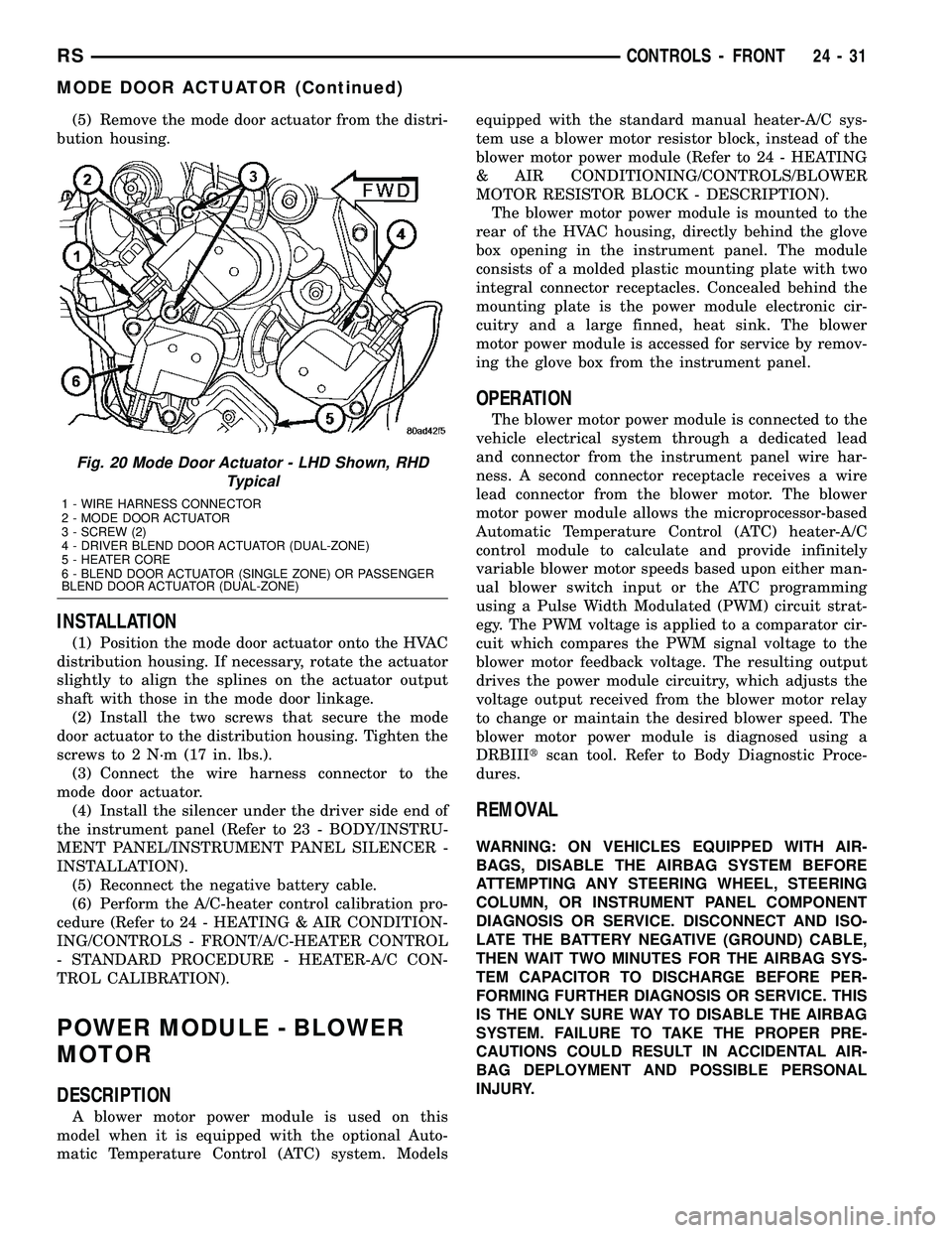
(5) Remove the mode door actuator from the distri-
bution housing.
INSTALLATION
(1) Position the mode door actuator onto the HVAC
distribution housing. If necessary, rotate the actuator
slightly to align the splines on the actuator output
shaft with those in the mode door linkage.
(2) Install the two screws that secure the mode
door actuator to the distribution housing. Tighten the
screws to 2 N´m (17 in. lbs.).
(3) Connect the wire harness connector to the
mode door actuator.
(4) Install the silencer under the driver side end of
the instrument panel (Refer to 23 - BODY/INSTRU-
MENT PANEL/INSTRUMENT PANEL SILENCER -
INSTALLATION).
(5) Reconnect the negative battery cable.
(6) Perform the A/C-heater control calibration pro-
cedure (Refer to 24 - HEATING & AIR CONDITION-
ING/CONTROLS - FRONT/A/C-HEATER CONTROL
- STANDARD PROCEDURE - HEATER-A/C CON-
TROL CALIBRATION).
POWER MODULE - BLOWER
MOTOR
DESCRIPTION
A blower motor power module is used on this
model when it is equipped with the optional Auto-
matic Temperature Control (ATC) system. Modelsequipped with the standard manual heater-A/C sys-
tem use a blower motor resistor block, instead of the
blower motor power module (Refer to 24 - HEATING
& AIR CONDITIONING/CONTROLS/BLOWER
MOTOR RESISTOR BLOCK - DESCRIPTION).
The blower motor power module is mounted to the
rear of the HVAC housing, directly behind the glove
box opening in the instrument panel. The module
consists of a molded plastic mounting plate with two
integral connector receptacles. Concealed behind the
mounting plate is the power module electronic cir-
cuitry and a large finned, heat sink. The blower
motor power module is accessed for service by remov-
ing the glove box from the instrument panel.
OPERATION
The blower motor power module is connected to the
vehicle electrical system through a dedicated lead
and connector from the instrument panel wire har-
ness. A second connector receptacle receives a wire
lead connector from the blower motor. The blower
motor power module allows the microprocessor-based
Automatic Temperature Control (ATC) heater-A/C
control module to calculate and provide infinitely
variable blower motor speeds based upon either man-
ual blower switch input or the ATC programming
using a Pulse Width Modulated (PWM) circuit strat-
egy. The PWM voltage is applied to a comparator cir-
cuit which compares the PWM signal voltage to the
blower motor feedback voltage. The resulting output
drives the power module circuitry, which adjusts the
voltage output received from the blower motor relay
to change or maintain the desired blower speed. The
blower motor power module is diagnosed using a
DRBIIItscan tool. Refer to Body Diagnostic Proce-
dures.
REMOVAL
WARNING: ON VEHICLES EQUIPPED WITH AIR-
BAGS, DISABLE THE AIRBAG SYSTEM BEFORE
ATTEMPTING ANY STEERING WHEEL, STEERING
COLUMN, OR INSTRUMENT PANEL COMPONENT
DIAGNOSIS OR SERVICE. DISCONNECT AND ISO-
LATE THE BATTERY NEGATIVE (GROUND) CABLE,
THEN WAIT TWO MINUTES FOR THE AIRBAG SYS-
TEM CAPACITOR TO DISCHARGE BEFORE PER-
FORMING FURTHER DIAGNOSIS OR SERVICE. THIS
IS THE ONLY SURE WAY TO DISABLE THE AIRBAG
SYSTEM. FAILURE TO TAKE THE PROPER PRE-
CAUTIONS COULD RESULT IN ACCIDENTAL AIR-
BAG DEPLOYMENT AND POSSIBLE PERSONAL
INJURY.
Fig. 20 Mode Door Actuator - LHD Shown, RHD
Typical
1 - WIRE HARNESS CONNECTOR
2 - MODE DOOR ACTUATOR
3 - SCREW (2)
4 - DRIVER BLEND DOOR ACTUATOR (DUAL-ZONE)
5 - HEATER CORE
6 - BLEND DOOR ACTUATOR (SINGLE ZONE) OR PASSENGER
BLEND DOOR ACTUATOR (DUAL-ZONE)
RSCONTROLS - FRONT24-31
MODE DOOR ACTUATOR (Continued)
Page 2428 of 2585
REMOVAL
WARNING: ON VEHICLES EQUIPPED WITH AIR-
BAGS, DISABLE THE AIRBAG SYSTEM BEFORE
ATTEMPTING ANY STEERING WHEEL, STEERING
COLUMN, OR INSTRUMENT PANEL COMPONENT
DIAGNOSIS OR SERVICE. DISCONNECT AND ISO-
LATE THE BATTERY NEGATIVE (GROUND) CABLE,
THEN WAIT TWO MINUTES FOR THE AIRBAG SYS-
TEM CAPACITOR TO DISCHARGE BEFORE PER-
FORMING FURTHER DIAGNOSIS OR SERVICE. THIS
IS THE ONLY SURE WAY TO DISABLE THE AIRBAG
SYSTEM. FAILURE TO TAKE THE PROPER PRE-
CAUTIONS COULD RESULT IN ACCIDENTAL AIR-
BAG DEPLOYMENT AND POSSIBLE PERSONAL
INJURY.
(1) Disconnect and isolate the battery negative
cable.
(2) Pull the carpet on the passenger side front
floor away from the dash panel far enough to access
the recirculation door actuator.
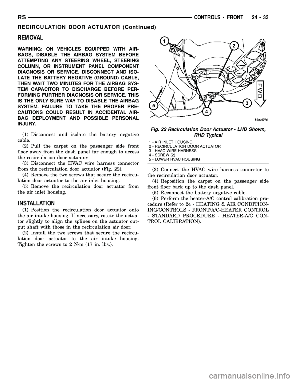
(3) Disconnect the HVAC wire harness connector
from the recirculation door actuator (Fig. 22).
(4) Remove the two screws that secure the recircu-
lation door actuator to the air inlet housing.
(5) Remove the recirculation door actuator from
the air inlet housing.
INSTALLATION
(1) Position the recirculation door actuator onto
the air intake housing. If necessary, rotate the actua-
tor slightly to align the splines on the actuator out-
put shaft with those in the recirculation air door.
(2) Install the two screws that secure the recircu-
lation door actuator to the air intake housing.
Tighten the screws to 2 N´m (17 in. lbs.).(3) Connect the HVAC wire harness connector to
the recirculation door actuator.
(4) Reposition the carpet on the passenger side
front floor back up to the dash panel.
(5) Reconnect the battery negative cable.
(6) Perform the heater-A/C control calibration pro-
cedure (Refer to 24 - HEATING & AIR CONDITION-
ING/CONTROLS - FRONT/A/C-HEATER CONTROL
- STANDARD PROCEDURE - HEATER-A/C CON-
TROL CALIBRATION).
Fig. 22 Recirculation Door Actuator - LHD Shown,
RHD Typical
1 - AIR INLET HOUSING
2 - RECIRCULATION DOOR ACTUATOR
3 - HVAC WIRE HARNESS
4 - SCREW (2)
5 - LOWER HVAC HOUSING
RSCONTROLS - FRONT24-33
RECIRCULATION DOOR ACTUATOR (Continued)
Page 2440 of 2585
system, the center outlet of the three has fixed vanes
and also houses the remote front infrared tempera-
ture sensors.
WARNING: ON VEHICLES EQUIPPED WITH AIR-
BAGS, DISABLE THE AIRBAG SYSTEM BEFORE
ATTEMPTING ANY STEERING WHEEL, STEERING
COLUMN, OR INSTRUMENT PANEL COMPONENT
DIAGNOSIS OR SERVICE. DISCONNECT AND ISO-
LATE THE BATTERY NEGATIVE (GROUND) CABLE,
THEN WAIT TWO MINUTES FOR THE AIRBAG SYS-
TEM CAPACITOR TO DISCHARGE BEFORE PER-
FORMING FURTHER DIAGNOSIS OR SERVICE. THIS
IS THE ONLY SURE WAY TO DISABLE THE AIRBAG
SYSTEM. FAILURE TO TAKE THE PROPER PRE-
CAUTIONS COULD RESULT IN ACCIDENTAL AIR-
BAG DEPLOYMENT AND POSSIBLE PERSONAL
INJURY.
(1) Disconnect and isolate the negative battery
cable.
(2) Remove the center bezel from the instrument
panel (Refer to 23 - BODY/INSTRUMENT PANEL/
INSTRUMENT PANEL CENTER BEZEL -
REMOVAL).
(3) Place the center bezel face down on a suitable
work surface. Be certain to take the proper precau-
tions to protect the face of the center bezel from cos-
metic damage.
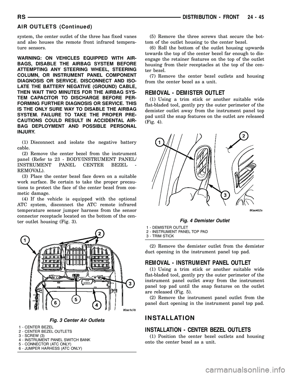
(4) If the vehicle is equipped with the optional
ATC system, disconnect the ATC remote infrared
temperature sensor jumper harness from the sensor
connector receptacle located on the bottom of the cen-
ter outlet housing (Fig. 3).(5) Remove the three screws that secure the bot-
tom of the outlet housing to the center bezel.
(6) Roll the bottom of the outlet housing upwards
towards the top of the center bezel far enough to dis-
engage the retainer features on the top of the outlet
housing from their receptacles at the top of the cen-
ter bezel.
(7) Remove the center bezel outlets and housing
from the center bezel as a unit.
REMOVAL - DEMISTER OUTLET
(1) Using a trim stick or another suitable wide
flat-bladed tool, gently pry the outer perimeter of the
demister outlet away from the instrument panel top
pad until the snap features on the outlet are released
(Fig. 4).
(2) Remove the demister outlet from the demister
duct opening in the instrument panel top pad.
REMOVAL - INSTRUMENT PANEL OUTLET
(1) Using a trim stick or another suitable wide
flat-bladed tool, gently pry the outer perimeter of the
instrument panel outlet away from the instrument
panel top pad until the snap features on the outlet
are released (Fig. 5).
(2) Remove the instrument panel outlet from the
panel duct opening in the instrument panel top pad.
INSTALLATION
INSTALLATION - CENTER BEZEL OUTLETS
(1) Position the center bezel outlets and housing
onto the center bezel as a unit.
Fig. 3 Center Air Outlets
1 - CENTER BEZEL
2 - CENTER BEZEL OUTLETS
3 - SCREW (3)
4 - INSTRUMENT PANEL SWITCH BANK
5 - CONNECTOR (ATC ONLY)
6 - JUMPER HARHESS (ATC ONLY)
Fig. 4 Demister Outlet
1 - DEMISTER OUTLET
2 - INSTRUMENT PANEL TOP PAD
3 - TRIM STICK
RSDISTRIBUTION - FRONT24-45
AIR OUTLETS (Continued)
Page 2442 of 2585
blower motor to regulate the blower motor ground
path it provides. The blower motor and wheel are
used to control the velocity of air moving through the
HVAC housing by spinning the blower wheel within
the housing at the selected speed or, in the ATC sys-
tem, at the selected or programmed speed.
DIAGNOSIS AND TESTING - BLOWER MOTOR
BLOWER MOTOR INOPERATIVE
WARNING: ON VEHICLES EQUIPPED WITH AIR-
BAGS, DISABLE THE AIRBAG SYSTEM BEFORE
ATTEMPTING ANY STEERING WHEEL, STEERING
COLUMN, OR INSTRUMENT PANEL COMPONENT
DIAGNOSIS OR SERVICE. DISCONNECT AND ISO-
LATE THE BATTERY NEGATIVE (GROUND) CABLE,
THEN WAIT TWO MINUTES FOR THE AIRBAG SYS-
TEM CAPACITOR TO DISCHARGE BEFORE PER-
FORMING FURTHER DIAGNOSIS OR SERVICE. THIS
IS THE ONLY SURE WAY TO DISABLE THE AIRBAG
SYSTEM. FAILURE TO TAKE THE PROPER PRE-
CAUTIONS COULD RESULT IN ACCIDENTAL AIR-
BAG DEPLOYMENT AND POSSIBLE PERSONAL
INJURY.
For circuit descriptions and diagrams, refer to the
appropriate wiring information. The wiring informa-
tion includes wiring, diagrams, proper wire and con-
nector repair procedures, further details on wire
harness routing and retention, as well as pin-out and
location views for the various wire harness connec-
tors, splices and grounds.
BLOWER MOTOR ELECTRICAL DIAGNOSIS
(1) Check the fuse (Fuse 10 - 40 ampere) in the
Integrated Power Module (IPM). If OK, go to Step 2.
If not OK, repair the shorted circuit or component as
required and replace the faulty fuse.
(2) Turn the ignition switch to the On position. Be
certain that the A/C-heater control power is turned
on. Check for battery voltage at the fuse (Fuse 10 -
40 ampere) in the IPM. If OK, go to Step 3. If not
OK, check the front blower motor relay.
(3) Turn the ignition switch to the Off position.
Disconnect and isolate the battery negative cable.
Disconnect the front HVAC wire harness connector
for the front blower motor resistor block (Manual
Temperature Control) or the front blower motor
power module (Automatic Temperature Control) from
the resistor or module connector receptacle. Recon-
nect the battery negative cable. Turn the ignition
switch to the On position. Be certain that the A/C-
heater control power is turned on. Check for battery
voltage at the fused front blower motor relay output
circuit cavity of the front HVAC wire harness connec-
tor for the front blower motor resistor block (MTC) orthe front blower motor power module (ATC). If OK,
go to Step 4. If not OK, repair the open fused front
blower motor relay output circuit to the IPM as
required.
(4) Turn the ignition switch to the Off position.
Disconnect and isolate the battery negative cable.
Disconnect the front blower motor pigtail wire con-
nector from the connector receptacle of the front
blower motor resistor block (MTC) or the front
blower motor power module (ATC). Use jumper wires
to connect a battery and ground feeds to the blower
motor pigtail wire connector. The blower motor
should operate. If OK with MTC, proceed to diagno-
sis of the front blower motor resistor block (Refer to
24 - HEATING & AIR CONDITIONING/CONTROLS
- FRONT/BLOWER MOTOR RESISTOR - DIAGNO-
SIS AND TESTING). If OK with ATC, use a DRBIII
scan tool to diagnose the front blower motor power
module. Refer to Body Diagnostic information. If not
OK with MTC or ATC, replace the faulty front blower
motor.
BLOWER MOTOR NOISE OR VIBRATION
Refer to the Blower Motor Noise/Vibration Diagno-
sis chart for basic checks of the blower motor when a
vibration or noise is present (Fig. 7).
REMOVAL
WARNING: ON VEHICLES EQUIPPED WITH AIR-
BAGS, DISABLE THE AIRBAG SYSTEM BEFORE
ATTEMPTING ANY STEERING WHEEL, STEERING
COLUMN, OR INSTRUMENT PANEL COMPONENT
DIAGNOSIS OR SERVICE. DISCONNECT AND ISO-
LATE THE BATTERY NEGATIVE (GROUND) CABLE,
THEN WAIT TWO MINUTES FOR THE AIRBAG SYS-
TEM CAPACITOR TO DISCHARGE BEFORE PER-
FORMING FURTHER DIAGNOSIS OR SERVICE. THIS
IS THE ONLY SURE WAY TO DISABLE THE AIRBAG
SYSTEM. FAILURE TO TAKE THE PROPER PRE-
CAUTIONS COULD RESULT IN AN ACCIDENTAL
AIRBAG DEPLOYMENT AND POSSIBLE PERSONAL
INJURY.
NOTE: The blower motor is located on the passen-
ger side of the vehicle under the instrument panel.
The blower motor can be removed from the vehicle
without having to remove the HVAC housing.
(1) Disconnect and isolate the battery negative
cable.
(2) Remove the passenger side door sill plate and
cowl panel.
(3) Pull back the carpet to access the front lower
air intake screw.
RSDISTRIBUTION - FRONT24-47
BLOWER MOTOR (Continued)
Page 2445 of 2585
(6) Install the four screws (from the bottom) that
secure the lower air inlet housing to the lower HVAC
housing. Tighten the screws to 2 N´m (17 in. lbs.).
(7) Install the one screw (from the top) that
secures the lower air inlet housing to the upper air
intake housing. Tighten the screws to 2 N´m (17 in.
lbs.).
(8) Connect the blower motor pigtail harness con-
nector to the blower motor resistor block or power
module, depending how vehicle is equipped.
(9) Install the recirculation door actuator (Refer to
24 - HEATING & AIR CONDITIONING/CONTROLS/
RECIRCULATION DOOR ACTUATOR - INSTALLA-
TION).
(10) Install the recirculation door actuator wire
harness lead into the routing clip on the lower air
inlet housing.
(11) Reinstall the carpet.
(12) Install the passenger side door sill plate and
cowl panel.
(13) Reconnect the battery negative cable.
(14) Perform the heater-A/C control calibration
procedure (Refer to 24 - HEATING & AIR CONDI-
TIONING/CONTROLS - FRONT/A/C-HEATER CON-
TROL - STANDARD PROCEDURE - HEATER-A/C
CONTROL CALIBRATION).
DEFROSTER DUCT
REMOVAL
WARNING: ON VEHICLES EQUIPPED WITH AIR-
BAGS, DISABLE THE AIRBAG SYSTEM BEFORE
ATTEMPTING ANY STEERING WHEEL, STEERING
COLUMN, OR INSTRUMENT PANEL COMPONENT
DIAGNOSIS OR SERVICE. DISCONNECT AND ISO-
LATE THE BATTERY NEGATIVE (GROUND) CABLE,
THEN WAIT TWO MINUTES FOR THE AIRBAG SYS-
TEM CAPACITOR TO DISCHARGE BEFORE PER-
FORMING FURTHER DIAGNOSIS OR SERVICE. THIS
IS THE ONLY SURE WAY TO DISABLE THE AIRBAG
SYSTEM. FAILURE TO TAKE THE PROPER PRE-
CAUTIONS COULD RESULT IN ACCIDENTAL AIR-
BAG DEPLOYMENT AND POSSIBLE PERSONAL
INJURY.
(1) Disconnect and isolate the battery negative
cable.
(2) Remove the instrument panel from the vehicle.
(Refer to 23 - BODY/INSTRUMENT PANEL/IN-
STRUMENT PANEL ASSEMBLY - REMOVAL).
(3) Place the instrument panel face down on a
suitable work surface. Be certain to take the proper
precautions to protect the face of the instrument
panel from cosmetic damage.(4) Remove the fasteners that secure the defroster
duct to the instrument panel armature.
(5) Remove the defroster duct from the instrument
panel.
INSTALLATION
WARNING: ON VEHICLES EQUIPPED WITH AIR-
BAGS, DISABLE THE AIRBAG SYSTEM BEFORE
ATTEMPTING ANY STEERING WHEEL, STEERING
COLUMN, OR INSTRUMENT PANEL COMPONENT
DIAGNOSIS OR SERVICE. DISCONNECT AND ISO-
LATE THE BATTERY NEGATIVE (GROUND) CABLE,
THEN WAIT TWO MINUTES FOR THE AIRBAG SYS-
TEM CAPACITOR TO DISCHARGE BEFORE PER-
FORMING FURTHER DIAGNOSIS OR SERVICE. THIS
IS THE ONLY SURE WAY TO DISABLE THE AIRBAG
SYSTEM. FAILURE TO TAKE THE PROPER PRE-
CAUTIONS COULD RESULT IN ACCIDENTAL AIR-
BAG DEPLOYMENT AND POSSIBLE PERSONAL
INJURY.
(1) Position the defroster duct to the instrument
panel.
(2) Install the fasteners that secure the defroster
duct to the instrument panel armature.
(3) Reinstall the instrument panel in the vehicle.
(Refer to 23 - BODY/INSTRUMENT PANEL/IN-
STRUMENT PANEL ASSEMBLY - INSTALLA-
TION).
(4) Reconnect the battery negative cable.
FLOOR DISTRIBUTION DUCTS
REMOVAL
(1) Roll back the carpet on the front floor from
under the instrument panel toward the rear of the
vehicle (Refer to 23 - BODY/INTERIOR/CARPETS
AND FLOOR MATS - REMOVAL).
(2) Lift the center floor distribution duct upward
far enough to disengage its locator hole from the
weld stud on the front floor panel (Fig. 11).
(3) Pull the center floor distribution duct rearward
far enough to disengage it from the floor outlet of the
HVAC housing.
(4) Disassemble the right and/or left floor distribu-
tion ducts from the center floor distribution duct as
required.
INSTALLATION
(1) Assemble the right and/or left floor distribution
ducts onto the center floor distribution duct as
required.
(2) Slide the center floor distribution duct under
the instrument panel center stack far enough to
engage it to the floor outlet of the HVAC housing.
24 - 50 DISTRIBUTION - FRONTRS
BLOWER MOTOR (Continued)
Page 2446 of 2585
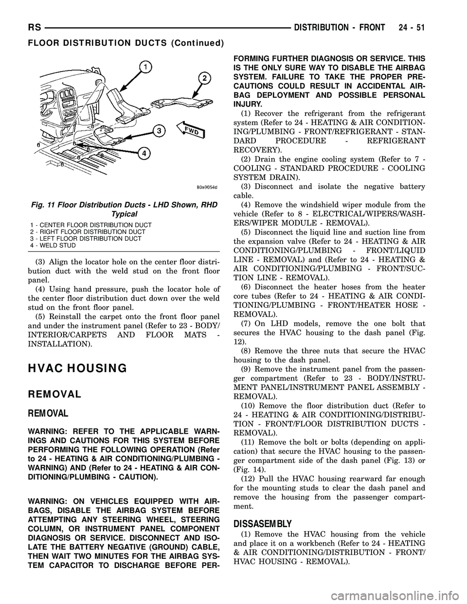
(3) Align the locator hole on the center floor distri-
bution duct with the weld stud on the front floor
panel.
(4) Using hand pressure, push the locator hole of
the center floor distribution duct down over the weld
stud on the front floor panel.
(5) Reinstall the carpet onto the front floor panel
and under the instrument panel (Refer to 23 - BODY/
INTERIOR/CARPETS AND FLOOR MATS -
INSTALLATION).
HVAC HOUSING
REMOVAL
REMOVAL
WARNING: REFER TO THE APPLICABLE WARN-
INGS AND CAUTIONS FOR THIS SYSTEM BEFORE
PERFORMING THE FOLLOWING OPERATION (Refer
to 24 - HEATING & AIR CONDITIONING/PLUMBING -
WARNING) AND (Refer to 24 - HEATING & AIR CON-
DITIONING/PLUMBING - CAUTION).
WARNING: ON VEHICLES EQUIPPED WITH AIR-
BAGS, DISABLE THE AIRBAG SYSTEM BEFORE
ATTEMPTING ANY STEERING WHEEL, STEERING
COLUMN, OR INSTRUMENT PANEL COMPONENT
DIAGNOSIS OR SERVICE. DISCONNECT AND ISO-
LATE THE BATTERY NEGATIVE (GROUND) CABLE,
THEN WAIT TWO MINUTES FOR THE AIRBAG SYS-
TEM CAPACITOR TO DISCHARGE BEFORE PER-FORMING FURTHER DIAGNOSIS OR SERVICE. THIS
IS THE ONLY SURE WAY TO DISABLE THE AIRBAG
SYSTEM. FAILURE TO TAKE THE PROPER PRE-
CAUTIONS COULD RESULT IN ACCIDENTAL AIR-
BAG DEPLOYMENT AND POSSIBLE PERSONAL
INJURY.
(1) Recover the refrigerant from the refrigerant
system (Refer to 24 - HEATING & AIR CONDITION-
ING/PLUMBING - FRONT/REFRIGERANT - STAN-
DARD PROCEDURE - REFRIGERANT
RECOVERY).
(2) Drain the engine cooling system (Refer to 7 -
COOLING - STANDARD PROCEDURE - COOLING
SYSTEM DRAIN).
(3) Disconnect and isolate the negative battery
cable.
(4) Remove the windshield wiper module from the
vehicle (Refer to 8 - ELECTRICAL/WIPERS/WASH-
ERS/WIPER MODULE - REMOVAL).
(5) Disconnect the liquid line and suction line from
the expansion valve (Refer to 24 - HEATING & AIR
CONDITIONING/PLUMBING - FRONT/LIQUID
LINE - REMOVAL) and (Refer to 24 - HEATING &
AIR CONDITIONING/PLUMBING - FRONT/SUC-
TION LINE - REMOVAL).
(6) Disconnect the heater hoses from the heater
core tubes (Refer to 24 - HEATING & AIR CONDI-
TIONING/PLUMBING - FRONT/HEATER HOSE -
REMOVAL).
(7) On LHD models, remove the one bolt that
secures the HVAC housing to the dash panel (Fig.
12).
(8) Remove the three nuts that secure the HVAC
housing to the dash panel.
(9) Remove the instrument panel from the passen-
ger compartment (Refer to 23 - BODY/INSTRU-
MENT PANEL/INSTRUMENT PANEL ASSEMBLY -
REMOVAL).
(10) Remove the floor distribution duct (Refer to
24 - HEATING & AIR CONDITIONING/DISTRIBU-
TION - FRONT/FLOOR DISTRIBUTION DUCTS -
REMOVAL).
(11) Remove the bolt or bolts (depending on appli-
cation) that secure the HVAC housing to the passen-
ger compartment side of the dash panel (Fig. 13) or
(Fig. 14).
(12) Pull the HVAC housing rearward far enough
for the mounting studs to clear the dash panel and
remove the housing from the passenger compart-
ment.
DISSASEMBLY
(1) Remove the HVAC housing from the vehicle
and place it on a workbench (Refer to 24 - HEATING
& AIR CONDITIONING/DISTRIBUTION - FRONT/
HVAC HOUSING - REMOVAL).
Fig. 11 Floor Distribution Ducts - LHD Shown, RHD
Typical
1 - CENTER FLOOR DISTRIBUTION DUCT
2 - RIGHT FLOOR DISTRIBUTION DUCT
3 - LEFT FLOOR DISTRIBUTION DUCT
4 - WELD STUD
RSDISTRIBUTION - FRONT24-51
FLOOR DISTRIBUTION DUCTS (Continued)
Page 2450 of 2585
INSTRUMENT PANEL
DEMISTER DUCTS
REMOVAL
WARNING: ON VEHICLES EQUIPPED WITH AIR-
BAGS, DISABLE THE AIRBAG SYSTEM BEFORE
ATTEMPTING ANY STEERING WHEEL, STEERING
COLUMN, OR INSTRUMENT PANEL COMPONENT
DIAGNOSIS OR SERVICE. DISCONNECT AND ISO-
LATE THE BATTERY NEGATIVE (GROUND) CABLE,
THEN WAIT TWO MINUTES FOR THE AIRBAG SYS-
TEM CAPACITOR TO DISCHARGE BEFORE PER-
FORMING FURTHER DIAGNOSIS OR SERVICE. THIS
IS THE ONLY SURE WAY TO DISABLE THE AIRBAG
SYSTEM. FAILURE TO TAKE THE PROPER PRE-
CAUTIONS COULD RESULT IN ACCIDENTAL AIR-
BAG DEPLOYMENT AND POSSIBLE PERSONAL
INJURY.
(1) Disconnect and isolate the battery negative
cable.
(2) Remove the instrument panel from the vehicle.
(Refer to 23 - BODY/INSTRUMENT PANEL/IN-
STRUMENT PANEL ASSEMBLY - REMOVAL).
(3) Place the instrument panel face down on a
suitable work surface. Be certain to take the proper
precautions to protect the face of the instrument
panel from cosmetic damage.
(4) Remove the fasteners that secure the demister
ducts to the instrument panel armature.
(5) Disengage the demister ducts from the demis-
ter outlets.
(6) Remove the demister ducts from the instru-
ment panel.
INSTALLATION
WARNING: ON VEHICLES EQUIPPED WITH AIR-
BAGS, DISABLE THE AIRBAG SYSTEM BEFORE
ATTEMPTING ANY STEERING WHEEL, STEERING
COLUMN, OR INSTRUMENT PANEL COMPONENT
DIAGNOSIS OR SERVICE. DISCONNECT AND ISO-
LATE THE BATTERY NEGATIVE (GROUND) CABLE,
THEN WAIT TWO MINUTES FOR THE AIRBAG SYS-
TEM CAPACITOR TO DISCHARGE BEFORE PER-
FORMING FURTHER DIAGNOSIS OR SERVICE. THIS
IS THE ONLY SURE WAY TO DISABLE THE AIRBAG
SYSTEM. FAILURE TO TAKE THE PROPER PRE-
CAUTIONS COULD RESULT IN ACCIDENTAL AIR-
BAG DEPLOYMENT AND POSSIBLE PERSONAL
INJURY.
(1) Position the demister ducts to the instrument
panel.(2) Engage the demister ducts to the demister out-
lets.
(3) Install the fasteners that secure the demister
ducts to the instrument panel armature.
(4) Reinstall the instrument panel into the vehicle.
(Refer to 23 - BODY/INSTRUMENT PANEL/IN-
STRUMENT PANEL ASSEMBLY - INSTALLA-
TION).
(5) Reconnect the battery negative cable.
INSTRUMENT PANEL DUCTS
REMOVAL
WARNING: ON VEHICLES EQUIPPED WITH AIR-
BAGS, DISABLE THE AIRBAG SYSTEM BEFORE
ATTEMPTING ANY STEERING WHEEL, STEERING
COLUMN, OR INSTRUMENT PANEL COMPONENT
DIAGNOSIS OR SERVICE. DISCONNECT AND ISO-
LATE THE BATTERY NEGATIVE (GROUND) CABLE,
THEN WAIT TWO MINUTES FOR THE AIRBAG SYS-
TEM CAPACITOR TO DISCHARGE BEFORE PER-
FORMING FURTHER DIAGNOSIS OR SERVICE. THIS
IS THE ONLY SURE WAY TO DISABLE THE AIRBAG
SYSTEM. FAILURE TO TAKE THE PROPER PRE-
CAUTIONS COULD RESULT IN ACCIDENTAL AIR-
BAG DEPLOYMENT AND POSSIBLE PERSONAL
INJURY.
(1) Disconnect and isolate the battery negative
cable.
(2) Remove the instrument panel from the vehicle
(Refer to 23 - BODY/INSTRUMENT PANEL/IN-
STRUMENT PANEL ASSEMBLY - REMOVAL).
(3) Place the instrument panel face down on a
suitable work surface. Be certain to take the proper
precautions to protect the face of the instrument
panel from cosmetic damage.
(4) Remove the screws that secure the panel ducts
to the instrument panel armature.
(5) Disengage the panel ducts from the panel out-
lets.
(6) Remove the panel ducts from the instrument
panel.
INSTALLATION
(1) Position the panel ducts to the instrument
panel.
(2) Engage the panel ducts to the panel outlets.
(3) Install the screws that secure the panel ducts
to the instrument panel armature.
(4) Reinstall the instrument panel into the vehicle
(Refer to 23 - BODY/INSTRUMENT PANEL/IN-
STRUMENT PANEL ASSEMBLY - INSTALLA-
TION).
(5) Reconnect the battery negative cable.
RSDISTRIBUTION - FRONT24-55
Page 2475 of 2585
INSTALLATION
(1) Position the discharge line into the engine com-
partment.
(2) Remove the tape or plugs from the compressor
discharge port and the discharge line fitting.
(3) Lubricate a new rubber O-ring seal with clean
refrigerant oil and install it on the discharge line fit-
ting.
(4) Install a new dual plane seal and reconnect the
discharge line fitting to the compressor discharge
port on the top of the compressor.
(5) Install the nut that secures the discharge line
fitting to the compressor. Tighten the nut to 23 N´m
(17 ft. lbs.).
(6) Remove the tape or plugs from the condenser
inlet port and the discharge line fitting.
(7) Lubricate a new rubber O-ring seal with clean
refrigerant oil and install it on the discharge line fit-
ting.
(8) Install a new dual plane seal and reconnect the
discharge line fitting to the condenser inlet port on
the right side of the cooling module.
(9) Install the nut that secures the discharge line
fitting to the condenser. Tighten the nut to 23 N´m
(17 ft. lbs.).
(10) Position the radiator sight shield onto the
radiator closure panel crossmember.
(11) Install the five small screws that secure the
front fascia grille inserts to the radiator sight shield.
Tighten the screws to 2 N´m (17 in. lbs.).
(12) Install and tighten the two large screws that
secure the front fascia and the outboard ends of the
radiator sight shield to the radiator closure panel
crossmember. Tighten the screws to 6 N´m (53 in.
lbs.).
(13) Evacuate the refrigerant system (Refer to 24 -
HEATING & AIR CONDITIONING/PLUMBING -
FRONT/REFRIGERANT - STANDARD PROCE-
DURE - REFRIGERANT SYSTEM EVACUATE).
(14) Charge the refrigerant system (Refer to 24 -
HEATING & AIR CONDITIONING/PLUMBING -
FRONT/REFRIGERANT - STANDARD PROCE-
DURE - REFRIGERANT SYSTEM CHARGE).
A/C EVAPORATOR
DESCRIPTION
The A/C evaporator is located in the HVAC hous-
ing, behind the instrument panel. The evaporator is
positioned in the housing so that all air that enters
the housing must pass over the fins of the evaporator
coils before it is distributed through the system ducts
and outlets. However, air passing over the evaporator
fins will only be conditioned when the compressor isengaged and circulating refrigerant through the
evaporator tubes.
OPERATION
Refrigerant enters the A/C evaporator from the
expansion valve as a low-temperature, low-pressure
liquid. As air flows over the fins of the evaporator,
the humidity in the air condenses on the fins, and
the heat from the air is absorbed by the refrigerant.
Heat absorption causes the refrigerant to boil and
vaporize. The refrigerant becomes a low-pressure gas
when it leaves the evaporator.
The A/C evaporator cannot be repaired and, if
faulty or damaged, it must be replaced.
REMOVAL
WARNING: ON VEHICLES EQUIPPED WITH AIR-
BAGS, DISABLE THE AIRBAG SYSTEM BEFORE
ATTEMPTING ANY STEERING WHEEL, STEERING
COLUMN, OR INSTRUMENT PANEL COMPONENT
DIAGNOSIS OR SERVICE. DISCONNECT AND ISO-
LATE THE BATTERY NEGATIVE (GROUND) CABLE,
THEN WAIT TWO MINUTES FOR THE AIRBAG SYS-
TEM CAPACITOR TO DISCHARGE BEFORE PER-
FORMING FURTHER DIAGNOSIS OR SERVICE. THIS
IS THE ONLY SURE WAY TO DISABLE THE AIRBAG
SYSTEM. FAILURE TO TAKE THE PROPER PRE-
CAUTIONS COULD RESULT IN ACCIDENTAL AIR-
BAG DEPLOYMENT AND POSSIBLE PERSONAL
INJURY.
(1) Remove the HVAC housing (Refer to 24 -
HEATING & AIR CONDITIONING/DISTRIBUTION/
HVAC HOUSING - REMOVAL).
(2) Disassemble the HVAC housing to access the
evaporator (Refer to 24 - HEATING & AIR CONDI-
TIONING/DISTRIBUTION/HVAC HOUSING - DIS-
ASSEMBLY).
(3) Carefully lift the evaporator and its foam wrap
out of the lower half of the HVAC housing as a unit.
Be certain not to lose the clam shell type rubber seal
that is fitted to the evaporator inlet and outlet tubes
where they exit the HVAC housing.
INSTALLATION
NOTE: If the evaporator is being replaced, add 50
milliliters (1.8 fluid ounces) of refrigerant oil to the
refrigerant system. Use only refrigerant oil of the
type recommended for the compressor in the vehi-
cle.
(1) Carefully lower the evaporator and its foam
wrap into the lower half of the HVAC housing as a
unit. Be certain that the clam shell type rubber seal
24 - 80 PLUMBING - FRONTRS
A/C DISCHARGE LINE (Continued)