2004 CHRYSLER VOYAGER set clock
[x] Cancel search: set clockPage 2430 of 2585

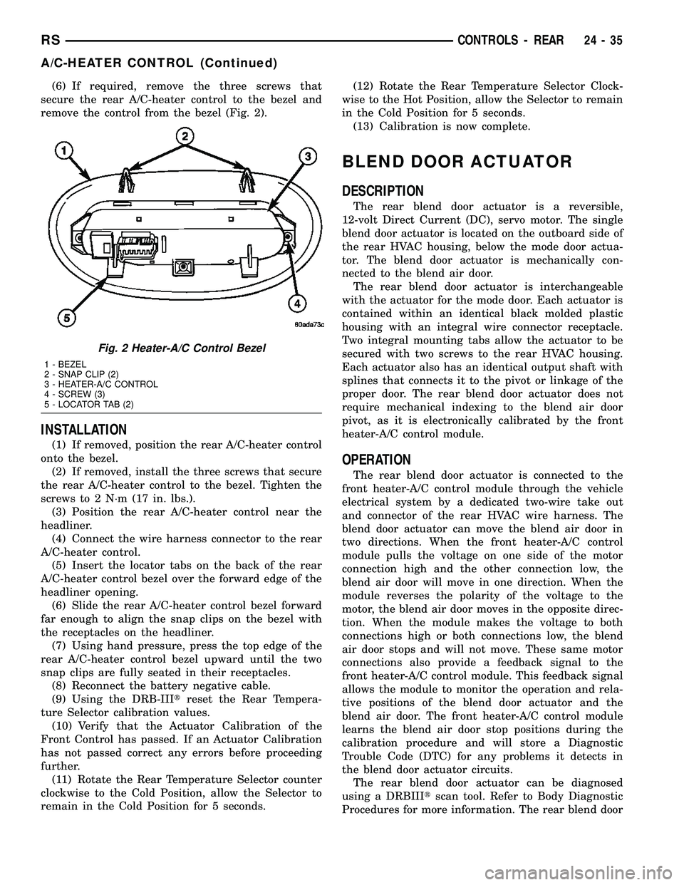
(6) If required, remove the three screws that
secure the rear A/C-heater control to the bezel and
remove the control from the bezel (Fig. 2).
INSTALLATION
(1) If removed, position the rear A/C-heater control
onto the bezel.
(2) If removed, install the three screws that secure
the rear A/C-heater control to the bezel. Tighten the
screws to 2 N´m (17 in. lbs.).
(3) Position the rear A/C-heater control near the
headliner.
(4) Connect the wire harness connector to the rear
A/C-heater control.
(5) Insert the locator tabs on the back of the rear
A/C-heater control bezel over the forward edge of the
headliner opening.
(6) Slide the rear A/C-heater control bezel forward
far enough to align the snap clips on the bezel with
the receptacles on the headliner.
(7) Using hand pressure, press the top edge of the
rear A/C-heater control bezel upward until the two
snap clips are fully seated in their receptacles.
(8) Reconnect the battery negative cable.
(9) Using the DRB-IIItreset the Rear Tempera-
ture Selector calibration values.
(10) Verify that the Actuator Calibration of the
Front Control has passed. If an Actuator Calibration
has not passed correct any errors before proceeding
further.
(11) Rotate the Rear Temperature Selector counter
clockwise to the Cold Position, allow the Selector to
remain in the Cold Position for 5 seconds.(12) Rotate the Rear Temperature Selector Clock-
wise to the Hot Position, allow the Selector to remain
in the Cold Position for 5 seconds.
(13) Calibration is now complete.
BLEND DOOR ACTUATOR
DESCRIPTION
The rear blend door actuator is a reversible,
12-volt Direct Current (DC), servo motor. The single
blend door actuator is located on the outboard side of
the rear HVAC housing, below the mode door actua-
tor. The blend door actuator is mechanically con-
nected to the blend air door.
The rear blend door actuator is interchangeable
with the actuator for the mode door. Each actuator is
contained within an identical black molded plastic
housing with an integral wire connector receptacle.
Two integral mounting tabs allow the actuator to be
secured with two screws to the rear HVAC housing.
Each actuator also has an identical output shaft with
splines that connects it to the pivot or linkage of the
proper door. The rear blend door actuator does not
require mechanical indexing to the blend air door
pivot, as it is electronically calibrated by the front
heater-A/C control module.
OPERATION
The rear blend door actuator is connected to the
front heater-A/C control module through the vehicle
electrical system by a dedicated two-wire take out
and connector of the rear HVAC wire harness. The
blend door actuator can move the blend air door in
two directions. When the front heater-A/C control
module pulls the voltage on one side of the motor
connection high and the other connection low, the
blend air door will move in one direction. When the
module reverses the polarity of the voltage to the
motor, the blend air door moves in the opposite direc-
tion. When the module makes the voltage to both
connections high or both connections low, the blend
air door stops and will not move. These same motor
connections also provide a feedback signal to the
front heater-A/C control module. This feedback signal
allows the module to monitor the operation and rela-
tive positions of the blend door actuator and the
blend air door. The front heater-A/C control module
learns the blend air door stop positions during the
calibration procedure and will store a Diagnostic
Trouble Code (DTC) for any problems it detects in
the blend door actuator circuits.
The rear blend door actuator can be diagnosed
using a DRBIIItscan tool. Refer to Body Diagnostic
Procedures for more information. The rear blend door
Fig. 2 Heater-A/C Control Bezel
1 - BEZEL
2 - SNAP CLIP (2)
3 - HEATER-A/C CONTROL
4 - SCREW (3)
5 - LOCATOR TAB (2)
RSCONTROLS - REAR24-35
A/C-HEATER CONTROL (Continued)
Page 2465 of 2585

tion that meets SAE Standard J2210 to the refriger-
ant system.
(2) Attach a clamp-on thermocouple to the liquid
line. The thermocouple must be placed as close to the
A/C pressure transducer as possible to accurately
observe liquid line temperature.
(3) Bring the refrigerant system up to operating
temperature and pressure. This is done by allowing
the engine to run at idle under the following condi-
tions for five minutes.
(a) Front windows are open.
(b) Transaxle in Park.
(c) Front heater-A/C controls set to outside air,
full cool, panel mode, blower high, and compressor
engaged.
(d) If the vehicle is so equipped, the rear heater-
A/C controls must be set to full cool and blower
high.
(4) Raise the liquid line (discharge) pressure to
about 1793 kPa (260 psi) by placing a piece of card-
board over part of the front side of the condenser. To
place the cardboard properly, remove the upper radi-
ator sight shield from the front fascia. Cover only
enough of the condenser to raise and maintain the
liquid line pressure at the specified level.
(5) Observe the liquid line (discharge) pressure
and liquid line temperature. Using the Charge Deter-
mination Chart (Fig. 2), determine whether the
refrigerant system is operating within the Proper
Charge Range.
(a) If the refrigerant system is operating in the
Undercharged area of the chart, add 0.057 kilo-
gram (0.125 pound or 2 ounces) of refrigerant to
the system.
(b) If the refrigerant system is operating in the
Overcharged area of the chart, reclaim 0.057 kilo-
gram (0.125 pound or 2 ounces) of refrigerant from
the system.
(6) Recheck the system charge level following each
refrigerant adjustment. Continue this process until
the system readings are in the Proper Charge Range
area on the Charge Determination Chart (Fig. 2).
STANDARD PROCEDURE
STANDARD PROCEDURE - HANDLING TUBING
AND FITTINGS
CAUTION: The system must be completely empty
before opening any fitting or connection in the
refrigeration system. Open fittings with caution
even after the system has been emptied. If any
pressure is noticed as a fitting is loosened,
retighten fitting and evacuate the system again.
A good rule for the flexible hose lines is to keep theradius of all bends at least 10 times the diameter of
the hose. Sharper bends will reduce the flow of
refrigerant. The flexible hose lines should be routed
so they are at least 3 inches (80 mm) from the
exhaust manifold. Inspect all flexible hose lines to
make sure they are in good condition and properly
routed.
The use of correct wrenches when making connec-
tions is very important. Improper wrenches or
improper use of wrenches can damage the fittings.
The internal parts of the A/C system will remain sta-
ble as long as moisture-free refrigerant and refrig-
erant oil is used. Abnormal amounts of dirt,
moisture or air can upset the chemical stability.
This may cause operational troubles or even seri-
ous damage if present in more than very small
quantities. Before disconnecting a component,
clean the outside of the fittings thoroughly to pre-
vent contamination from entering the refrigerant
system.
When opening a refrigeration system, have every-
thing you will need to repair the system ready. This
will minimize the amount of time the system must
be opened. Cap or plug all lines and fittings as
soon as they are opened. This will help prevent the
entrance of dirt and moisture. All new lines and
components should be capped or sealed until they
are ready to be used. Before connecting a compo-
nent, clean the outside of the fittings thoroughly to
prevent contamination from entering the refrigerant
system.
All tools, including the refrigerant dispensing mani-
fold, the manifold gauge set, and test hoses should
be kept clean and dry.
Kinks in the refrigerant tubing or sharp bends in
the refrigerant hose lines will greatly reduce the
capacity of the entire system. High pressures are pro-
duced in the system when it is operating. Extreme
care must be exercised to make sure that all connec-
tions are pressure tight. Dirt and moisture can enter
the system when it is opened for repair or replace-
ment of lines or components. The refrigerant oil will
absorb moisture readily out of the air. This moisture
will convert into acids within a closed system.
STANDARD PROCEDURE - REFRIGERANT
SYSTEM SERVICE EQUIPMENT
WARNING: EYE PROTECTION MUST BE WORN
WHEN SERVICING AN AIR CONDITIONING REFRIG-
ERANT SYSTEM. TURN OFF (ROTATE CLOCKWISE)
ALL VALVES ON THE EQUIPMENT BEING USED
BEFORE CONNECTING TO, OR DISCONNECTING
FROM THE REFRIGERANT SYSTEM. FAILURE TO
OBSERVE THESE WARNINGS MAY RESULT IN PER-
SONAL INJURY.
24 - 70 PLUMBING - FRONTRS
PLUMBING - FRONT (Continued)
Page 2550 of 2585

CHAIN WEAR - STANDARD PROCEDURE,
MEASURING TIMING..................9-153
CHANGE - STANDARD PROCEDURE,
DIFFERENTIAL ASSEMBLY FLUID.........3-40
CHANGE - STANDARD PROCEDURE,
ENGINE OIL AND FILTER...........9-137,9-53
CHANGE - STANDARD PROCEDURE,
OVERRUNNING CLUTCH HOUSING
FLUID..............................3-41
CHANGE - STANDARD PROCEDURE, PTU
FLUID..............................21-5
CHANGER - DESCRIPTION, CD...........8A-7
CHANGER - INSTALLATION, CD..........8A-8
CHANGER - OPERATION, CD.............8A-7
CHANGER - REMOVAL, CD..............8A-8
CHANNEL - INSTALLATION, WATER.....23-121
CHANNEL - REMOVAL, WATER.........23-121
CHARGE - STANDARD PROCEDURE,
REFRIGERANT SYSTEM...............24-72
CHARGE LEVEL TEST - 2.5L DIESEL -
DIAGNOSIS AND TESTING, SYSTEM......24-68
CHARGE LEVEL TEST - GASOLINE
ENGINES - DIAGNOSIS AND TESTING,
SYSTEM............................24-67
CHARGING - STANDARD PROCEDURE,
CONVENTIONAL BATTERY..............8F-11
CHARGING - STANDARD PROCEDURE,
SPIRAL PLATE BATTERY...............8F-10
CHARGING SYSTEM - DESCRIPTION.....8F-20
CHARGING SYSTEM - OPERATION.......8F-20
CHARTS - DIAGNOSIS AND TESTING,
STEERING SYSTEM DIAGNOSIS...........19-3
CHARTS - SPECIFICATIONS, COLOR
CODE..............................23-84
CHATTER COMPLAINTS - DIAGNOSIS
AND TESTING, CLUTCH.................6-6
CHECK - DIAGNOSIS AND TESTING,
COOLING SYSTEM FLOW................7-3
CHECK - DIAGNOSIS AND TESTING,
EXHAUST SYSTEM RESTRICTION.........11-2
CHECK - STANDARD PROCEDURE,
COOLANT LEVEL.......................7-5
CHECK - STANDARD PROCEDURE,
ENGINE OIL LEVEL...................9-137
CHECK - STANDARD PROCEDURE, FLUID
LEVEL.............................21-71
CHECK, STANDARD PROCEDURE -
ENGINE OIL LEVEL....................9-53
CHECK, STANDARD PROCEDURE - FLUID
LEVEL AND CONDITION........21-201,21s-102
CHECK STRAP - INSTALLATION.........23-15
CHECK STRAP - REMOVAL.............23-15
CHECKING - STANDARD PROCEDURE,
BRAKE FLUID LEVEL..............5-32,5s-31
CHECKING - STANDARD PROCEDURE,
POWER STEERING FLUID LEVEL........19-44
CHECKING BATTERY ELECTROLYTE
LEVEL - STANDARD PROCEDURE........8F-14
CHECKING ENGINE OIL PRESSURE -
DIAGNOSIS AND TESTING..............9-52
CHECKING POWER STEERING BELT
TENSION - STANDARD PROCEDURE.......7-8
CHILD RESTRAINT ANCHOR -
DESCRIPTION........................8O-4
CHILD RESTRAINT ANCHOR -
OPERATION..........................8O-4
CHILD SEAT - INSTALLATION, QUAD.....23-89
CHILD SEAT - REMOVAL, QUAD.........23-89
CHILD SEAT MODULE, BENCH SEAT -
REMOVAL..........................23-87
CHIME SYSTEM - DIAGNOSIS AND
TESTING
............................8B-1
CHIME/BUZZER - DESCRIPTION
..........8B-1
CHIME/BUZZER - OPERATION
............8B-1
CHIME/BUZZER - WARNING
.............8B-1
CHIME/THERMISTOR - DESCRIPTION
....8N-10
CHIME/THERMISTOR - INSTALLATION
....8N-10
CHIME/THERMISTOR - OPERATION
......8N-10
CHIME/THERMISTOR - REMOVAL
.......8N-10
CHIRP PREFERENCE - STANDARD
PROCEDURE, HORN
..............8N-42,8N-5
CIRCUIT - DIAGNOSIS AND TESTING,
AMBIENT TEMPERATURE SENSOR
......8M-12
CIRCUIT FUNCTIONS - DESCRIPTION
. . 8W-01-6
CIRCUIT INFORMATION - DESCRIPTION
. 8W-01-5
CIRCUIT RESISTANCE TEST -
DIAGNOSIS AND TESTING, FEED
. . . 8F-32,8F-34CIRCUIT TEST - DIAGNOSIS AND
TESTING, CONTROL..............8F-30,8F-32
CIRCUIT TEST - DIAGNOSIS AND
TESTING, FEED.................8F-33,8F-35
CIRCUITS - OPERATION, NON-
MONITORED.........................25-5
CIRCUITS AND VALVES - OPERATION,
HYDRAULIC..........................5-83
CLAMP - STANDARD PROCEDURE,
HOSES..............................14-7
CLAMPS - DESCRIPTION, FUEL
LINES/HOSES........................14-6
CLAMPS - DESCRIPTION, HOSE...........7-1
CLAMPS - OPERATION, HOSE.............7-2
CLEAN, CLEANING...................21-114
CLEARANCE - STANDARD PROCEDURE,
MEASURING CONNECTING ROD
BEARING...........................9-120
CLEARANCE USING PLASTIGAGE -
STANDARD PROCEDURE, MEASURING
BEARING........................9-12,9-84
CLOCK SPRING - DESCRIPTION..........8O-4
CLOCK SPRING - INSTALLATION.........8O-5
CLOCK SPRING - OPERATION...........8O-4
CLOCK SPRING - REMOVAL.............8O-5
CLOCK SPRING CENTERING -
STANDARD PROCEDURE...............8O-5
CLUSTER - DESCRIPTION, INSTRUMENT . . . 8J-1
CLUSTER - OPERATION, INSTRUMENT.....8J-1
CLUSTER BEZEL - INSTALLATION........23-63
CLUSTER BEZEL - REMOVAL.............23-63
CLUSTER DIAGNOSIS - DIAGNOSIS AND
TESTING............................8J-2
CLUSTER ILLUMINATION LAMPS -
INSTALLATION.......................8L-21
CLUSTER ILLUMINATION LAMPS -
REMOVAL..........................8L-21
CLUSTER LENS - INSTALLATION........8J-10
CLUSTER LENS - REMOVAL............8J-10
CLUTCH - DESCRIPTION.................6-1
CLUTCH - DESCRIPTION, BI-
DIRECTIONAL OVERRUNNING...........3-34
CLUTCH - OPERATION, BI-DIRECTIONAL
OVERRUNNING.......................3-36
CLUTCH AIR PRESSURE TESTS -
DIAGNOSIS AND TESTING.......21-122,21s-30
CLUTCH ASSEMBLY - ASSEMBLY,
INPUT.....................21-216,21s-116
CLUTCH ASSEMBLY - DISASSEMBLY,
INPUT.....................21-208,21s-107
CLUTCH ASSY - 2.4L GAS -
INSTALLATION, MODULAR..............6-11
CLUTCH ASSY - 2.4L GAS - REMOVAL,
MODULAR...........................6-11
CLUTCH CHATTER COMPLAINTS -
DIAGNOSIS AND TESTING...............6-6
CLUTCH COIL - DIAGNOSIS AND
TESTING, A/C COMPRESSOR...........24-15
CLUTCH COVER AND DISC RUNOUT -
DIAGNOSIS AND TESTING...............6-6
CLUTCH DISC AND PRESSURE PLATE -
2.5L TD - INSTALLATION
...............6-12
CLUTCH DISC AND PRESSURE PLATE -
2.5L TD - REMOVAL
...................6-11
CLUTCH HOUSING FLUID CHANGE -
STANDARD PROCEDURE,
OVERRUNNING
.......................3-41
CLUTCH PEDAL INTERLOCK SWITCH -
INSTALLATION
........................6-14
CLUTCH PEDAL INTERLOCK SWITCH -
REMOVAL
...........................6-13
CLUTCH PEDAL UPSTOP SWITCH -
INSTALLATION
........................6-16
CLUTCH PEDAL UPSTOP SWITCH -
REMOVAL
...........................6-15
CLUTCH RELAY - DESCRIPTION, A/C
COMPRESSOR
.......................24-19
CLUTCH RELAY - INSTALLATION, A/C
COMPRESSOR
.......................24-20
CLUTCH RELAY - OPERATION, A/C
COMPRESSOR
.......................24-19
CLUTCH RELAY - REMOVAL, A/C
COMPRESSOR
.......................24-20
CLUTCH RELEASE LEVER AND BEARING
- INSTALLATION
.......................6-7
CLUTCH RELEASE LEVER AND BEARING
- REMOVAL
...........................6-6CLUTCH SYSTEM - DIAGNOSIS AND
TESTING.............................6-3
CLUTCH/COIL - DESCRIPTION, A/C
COMPRESSOR.......................24-15
CLUTCH/COIL - INSPECTION, A/C
COMPRESSOR.......................24-17
CLUTCH/COIL - INSTALLATION, A/C
COMPRESSOR.......................24-17
CLUTCH/COIL - OPERATION, A/C
COMPRESSOR.......................24-15
CLUTCH/COIL - REMOVAL, A/C
COMPRESSOR.......................24-16
CLUTCHES - DESCRIPTION, DRIVING . . . 21-190,
21s-95
CLUTCHES - DESCRIPTION, HOLDING . . . 21-207,
21s-106
CLUTCHES - OPERATION, DRIVING.....21-190,
21s-95
CLUTCHES - OPERATION, HOLDING....21-207,
21s-106
COAT/CLEARCOAT FINISH -
DESCRIPTION, BASE..................23-85
CODE - DESCRIPTION, PAINT...........23-85
CODE CHARTS - SPECIFICATIONS,
COLOR.............................23-84
CODE PLATE - DESCRIPTION, BODY....Intro.-1
CODES - STANDARD PROCEDURE,
ERASING TRANSMITTER..............8M-11
CODES - STANDARD PROCEDURE,
OBTAINING DIAGNOSTIC TROUBLE......8E-15
CODES - STANDARD PROCEDURE,
SETTING TRANSMITTER..............8M-11
COIL - DESCRIPTION, IGNITION............8I-6
COIL - DIAGNOSIS AND TESTING, A/C
COMPRESSOR CLUTCH...............24-15
COIL - OPERATION, IGNITION............8I-7
COLLAR - INSTALLATION, STRUCTURAL . . . 9-48
COLLAR - REMOVAL, STRUCTURAL.......9-47
COLOR CODE CHARTS -
SPECIFICATIONS.....................23-84
COLUMN - DESCRIPTION, STEERING.....19-10
COLUMN - DIAGNOSIS AND TESTING,
STEERING..........................19-12
COLUMN COVER - INSTALLATION,
LOWER STEERING...................23-70
COLUMN COVER - INSTALLATION, OVER
STEERING..........................23-70
COLUMN COVER - REMOVAL, LOWER
STEERING..........................23-70
COLUMN COVER - REMOVAL, OVER
STEERING..........................23-70
COLUMN COVER BACKING PLATE -
INSTALLATION, STEERING.............23-70
COLUMN COVER BACKING PLATE -
REMOVAL, STEERING.................23-70
COLUMN TORQUE, SPECIFICATIONS.....19-14
COMBUSTION PRESSURE LEAKAGE
TEST - DIAGNOSIS AND TESTING,
CYLINDER........................9-83,9-9
COMMON PROBLEM CAUSES -
DIAGNOSIS AND TESTING.............21-30
COMMUNICATION RECEIVE - PCM INPUT
- OPERATION, DATA BUS..............8E-15
COMMUNICATIONS INTERFACE (PCI)
BUS, OPERATION - PROGRAMMABLE....14-21
COMPASS CALIBRATION - STANDARD
PROCEDURE.........................8M-3
COMPASS DEMAGNETIZING -
STANDARD PROCEDURE...............8M-4
COMPASS MINI-TRIP COMPUTER -
DIAGNOSIS AND TESTING.............8M-10
COMPASS VARIATION ADJUSTMENT -
STANDARD PROCEDURE...............8M-5
COMPASS/MINI-TRIP COMPUTER -
DESCRIPTION........................8M-9
COMPASS/MINI-TRIP COMPUTER -
INSTALLATION......................8M-10
COMPASS/MINI-TRIP COMPUTER -
OPERATION.........................8M-9
COMPASS/MINI-TRIP COMPUTER -
REMOVAL..........................8M-10
COMPLAINTS - DIAGNOSIS AND
TESTING, CLUTCH CHATTER
..............6-6
COMPRESSION PRESSURE TEST -
DIAGNOSIS AND TESTING, CYLINDER
. . 9-83,9-9
COMPRESSOR - DESCRIPTION, A/C
......24-73
COMPRESSOR - OPERATION, A/C
........24-73
COMPRESSOR - REMOVAL
.............24-74
RSINDEX7
Description Group-Page Description Group-Page Description Group-Page