2004 CHRYSLER VOYAGER service indicator
[x] Cancel search: service indicatorPage 1333 of 2585
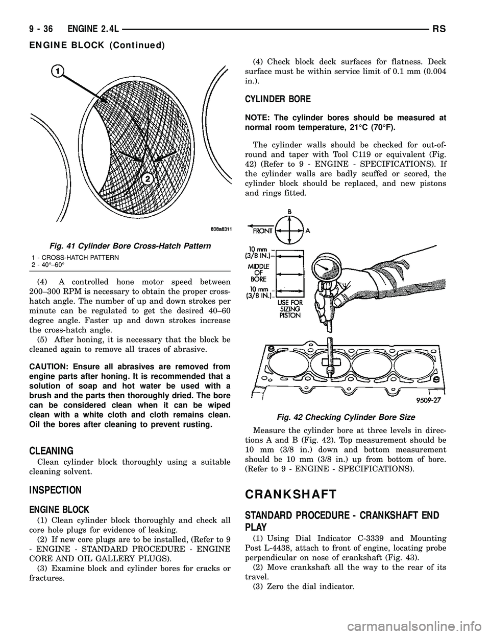
(4) A controlled hone motor speed between
200±300 RPM is necessary to obtain the proper cross-
hatch angle. The number of up and down strokes per
minute can be regulated to get the desired 40±60
degree angle. Faster up and down strokes increase
the cross-hatch angle.
(5) After honing, it is necessary that the block be
cleaned again to remove all traces of abrasive.
CAUTION: Ensure all abrasives are removed from
engine parts after honing. It is recommended that a
solution of soap and hot water be used with a
brush and the parts then thoroughly dried. The bore
can be considered clean when it can be wiped
clean with a white cloth and cloth remains clean.
Oil the bores after cleaning to prevent rusting.
CLEANING
Clean cylinder block thoroughly using a suitable
cleaning solvent.
INSPECTION
ENGINE BLOCK
(1) Clean cylinder block thoroughly and check all
core hole plugs for evidence of leaking.
(2) If new core plugs are to be installed, (Refer to 9
- ENGINE - STANDARD PROCEDURE - ENGINE
CORE AND OIL GALLERY PLUGS).
(3) Examine block and cylinder bores for cracks or
fractures.(4) Check block deck surfaces for flatness. Deck
surface must be within service limit of 0.1 mm (0.004
in.).
CYLINDER BORE
NOTE: The cylinder bores should be measured at
normal room temperature, 21ÉC (70ÉF).
The cylinder walls should be checked for out-of-
round and taper with Tool C119 or equivalent (Fig.
42) (Refer to 9 - ENGINE - SPECIFICATIONS). If
the cylinder walls are badly scuffed or scored, the
cylinder block should be replaced, and new pistons
and rings fitted.
Measure the cylinder bore at three levels in direc-
tions A and B (Fig. 42). Top measurement should be
10 mm (3/8 in.) down and bottom measurement
should be 10 mm (3/8 in.) up from bottom of bore.
(Refer to 9 - ENGINE - SPECIFICATIONS).
CRANKSHAFT
STANDARD PROCEDURE - CRANKSHAFT END
PLAY
(1) Using Dial Indicator C-3339 and Mounting
Post L-4438, attach to front of engine, locating probe
perpendicular on nose of crankshaft (Fig. 43).
(2) Move crankshaft all the way to the rear of its
travel.
(3) Zero the dial indicator.
Fig. 41 Cylinder Bore Cross-Hatch Pattern
1 - CROSS-HATCH PATTERN
2 - 40ɱ60É
Fig. 42 Checking Cylinder Bore Size
9 - 36 ENGINE 2.4LRS
ENGINE BLOCK (Continued)
Page 1721 of 2585
TORQUE CONVERTER LEAKAGE
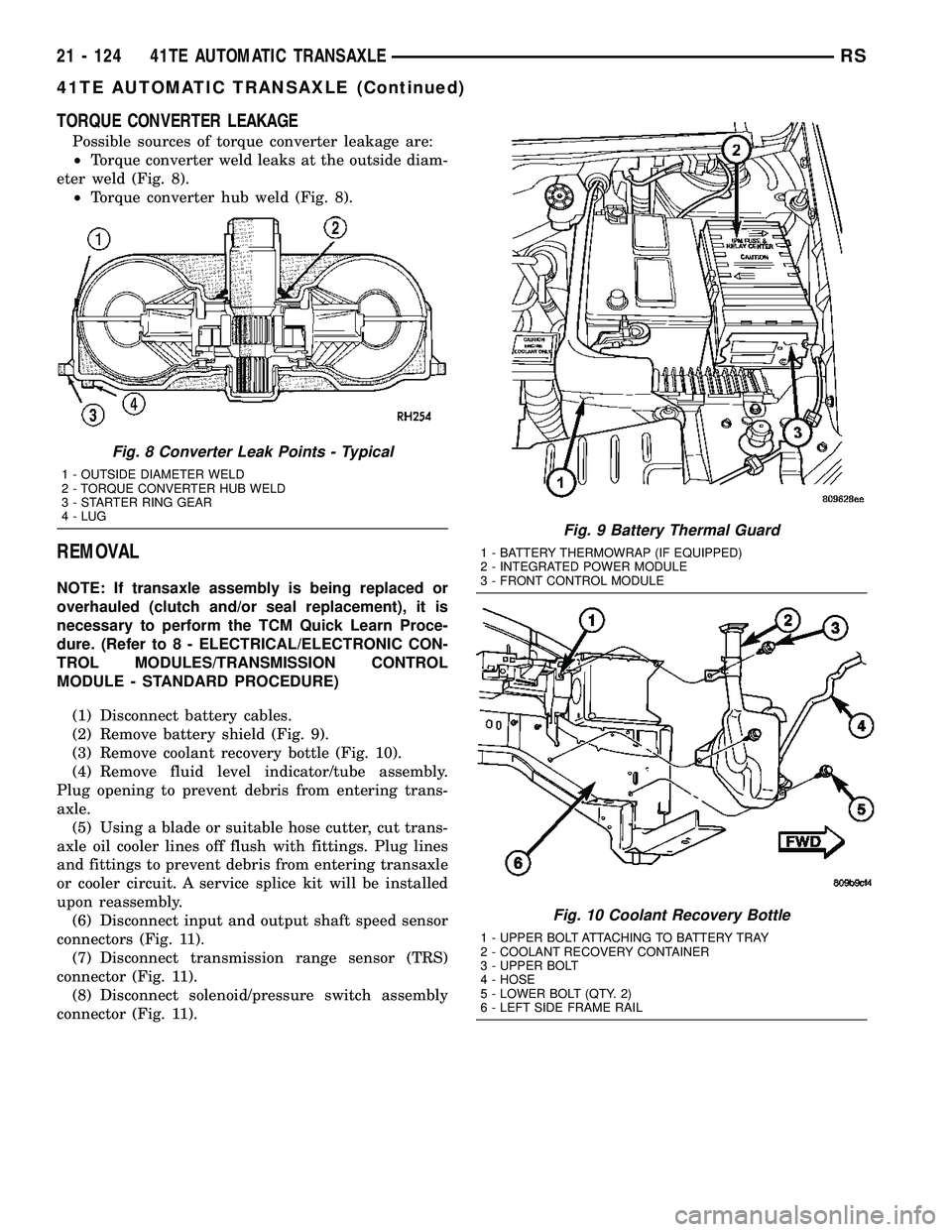
Possible sources of torque converter leakage are:
²Torque converter weld leaks at the outside diam-
eter weld (Fig. 8).
²Torque converter hub weld (Fig. 8).
REMOVAL
NOTE: If transaxle assembly is being replaced or
overhauled (clutch and/or seal replacement), it is
necessary to perform the TCM Quick Learn Proce-
dure. (Refer to 8 - ELECTRICAL/ELECTRONIC CON-
TROL MODULES/TRANSMISSION CONTROL
MODULE - STANDARD PROCEDURE)
(1) Disconnect battery cables.
(2) Remove battery shield (Fig. 9).
(3) Remove coolant recovery bottle (Fig. 10).
(4) Remove fluid level indicator/tube assembly.
Plug opening to prevent debris from entering trans-
axle.
(5) Using a blade or suitable hose cutter, cut trans-
axle oil cooler lines off flush with fittings. Plug lines
and fittings to prevent debris from entering transaxle
or cooler circuit. A service splice kit will be installed
upon reassembly.
(6) Disconnect input and output shaft speed sensor
connectors (Fig. 11).
(7) Disconnect transmission range sensor (TRS)
connector (Fig. 11).
(8) Disconnect solenoid/pressure switch assembly
connector (Fig. 11).
Fig. 8 Converter Leak Points - Typical
1 - OUTSIDE DIAMETER WELD
2 - TORQUE CONVERTER HUB WELD
3 - STARTER RING GEAR
4 - LUG
Fig. 9 Battery Thermal Guard
1 - BATTERY THERMOWRAP (IF EQUIPPED)
2 - INTEGRATED POWER MODULE
3 - FRONT CONTROL MODULE
Fig. 10 Coolant Recovery Bottle
1 - UPPER BOLT ATTACHING TO BATTERY TRAY
2 - COOLANT RECOVERY CONTAINER
3 - UPPER BOLT
4 - HOSE
5 - LOWER BOLT (QTY. 2)
6 - LEFT SIDE FRAME RAIL
21 - 124 41TE AUTOMATIC TRANSAXLERS
41TE AUTOMATIC TRANSAXLE (Continued)
Page 1765 of 2585
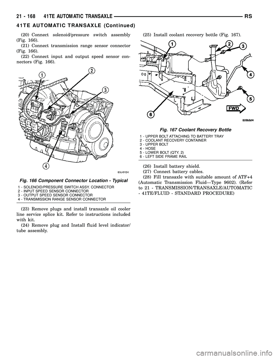
(20) Connect solenoid/pressure switch assembly
(Fig. 166).
(21) Connect transmission range sensor connector
(Fig. 166).
(22) Connect input and output speed sensor con-
nectors (Fig. 166).
(23) Remove plugs and install transaxle oil cooler
line service splice kit. Refer to instructions included
with kit.
(24) Remove plug and Install fluid level indicator/
tube assembly.(25) Install coolant recovery bottle (Fig. 167).
(26) Install battery shield.
(27) Connect battery cables.
(28) Fill transaxle with suitable amount of ATF+4
(Automatic Transmission FluidÐType 9602). (Refer
to 21 - TRANSMISSION/TRANSAXLE/AUTOMATIC
- 41TE/FLUID - STANDARD PROCEDURE)
Fig. 166 Component Connector Location - Typical
1 - SOLENOID/PRESSURE SWITCH ASSY. CONNECTOR
2 - INPUT SPEED SENSOR CONNECTOR
3 - OUTPUT SPEED SENSOR CONNECTOR
4 - TRANSMISSION RANGE SENSOR CONNECTOR
Fig. 167 Coolant Recovery Bottle
1 - UPPER BOLT ATTACHING TO BATTERY TRAY
2 - COOLANT RECOVERY CONTAINER
3 - UPPER BOLT
4 - HOSE
5 - LOWER BOLT (QTY. 2)
6 - LEFT SIDE FRAME RAIL
21 - 168 41TE AUTOMATIC TRANSAXLERS
41TE AUTOMATIC TRANSAXLE (Continued)
Page 1786 of 2585
OPERATION
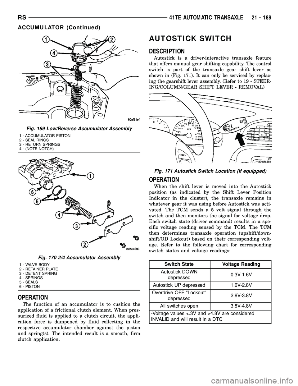
The function of an accumulator is to cushion the
application of a frictional clutch element. When pres-
surized fluid is applied to a clutch circuit, the appli-
cation force is dampened by fluid collecting in the
respective accumulator chamber against the piston
and spring(s). The intended result is a smooth, firm
clutch application.
AUTOSTICK SWITCH
DESCRIPTION
Autostick is a driver-interactive transaxle feature
that offers manual gear shifting capability. The control
switch is part of the transaxle gear shift lever as
shown in (Fig. 171). It can only be serviced by replac-
ing the gearshift lever assembly. (Refer to 19 - STEER-
ING/COLUMN/GEAR SHIFT LEVER - REMOVAL)
OPERATION
When the shift lever is moved into the Autostick
position (as indicated by the Shift Lever Position
Indicator in the cluster), the transaxle remains in
whatever gear it was using before Autostick was acti-
vated. The TCM sends a 5 volt signal through the
switch and then monitors the signal for voltage drop.
Each switch state (driver command) results in a spe-
cific voltage reading sensed by the TCM. The TCM
then determines transaxle operation (upshift/down-
shift/OD Lockout) based on their corresponding volt-
age. Refer to the following chart for corresponding
switch states and voltage readings:
Switch State Voltage Reading
Autostick DOWN
depressed0.3V-1.6V
Autostick UP depressed 1.6V-2.8V
Overdrive OFF9Lockout9
depressed2.8V-3.8V
All switches open 3.8V-4.8V
-Voltage values <.3V and >4.8V are considered
INVALID and will result in a DTC
Fig. 169 Low/Reverse Accumulator Assembly
1 - ACCUMULATOR PISTON
2 - SEAL RINGS
3 - RETURN SPRINGS
4 - (NOTE NOTCH)
Fig. 170 2/4 Accumulator Assembly
1 - VALVE BODY
2 - RETAINER PLATE
3 - DETENT SPRING
4 - SPRINGS
5 - SEALS
6 - PISTON
Fig. 171 Autostick Switch Location (if equipped)
RS41TE AUTOMATIC TRANSAXLE21 - 189
ACCUMULATOR (Continued)
Page 1800 of 2585
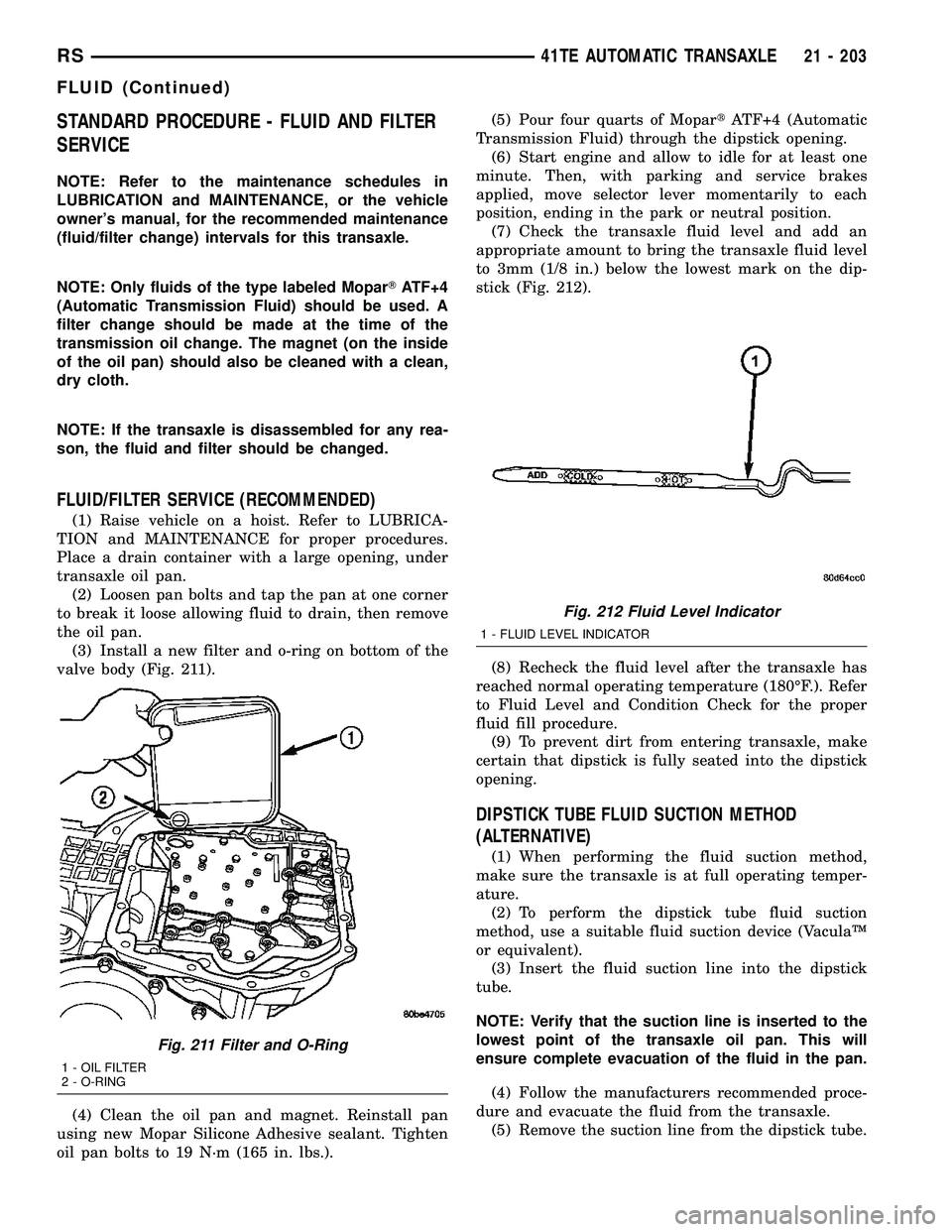
STANDARD PROCEDURE - FLUID AND FILTER
SERVICE
NOTE: Refer to the maintenance schedules in
LUBRICATION and MAINTENANCE, or the vehicle
owner's manual, for the recommended maintenance
(fluid/filter change) intervals for this transaxle.
NOTE: Only fluids of the type labeled MoparTATF+4
(Automatic Transmission Fluid) should be used. A
filter change should be made at the time of the
transmission oil change. The magnet (on the inside
of the oil pan) should also be cleaned with a clean,
dry cloth.
NOTE: If the transaxle is disassembled for any rea-
son, the fluid and filter should be changed.
FLUID/FILTER SERVICE (RECOMMENDED)
(1) Raise vehicle on a hoist. Refer to LUBRICA-
TION and MAINTENANCE for proper procedures.
Place a drain container with a large opening, under
transaxle oil pan.
(2) Loosen pan bolts and tap the pan at one corner
to break it loose allowing fluid to drain, then remove
the oil pan.
(3) Install a new filter and o-ring on bottom of the
valve body (Fig. 211).
(4) Clean the oil pan and magnet. Reinstall pan
using new Mopar Silicone Adhesive sealant. Tighten
oil pan bolts to 19 N´m (165 in. lbs.).(5) Pour four quarts of MopartATF+4 (Automatic
Transmission Fluid) through the dipstick opening.
(6) Start engine and allow to idle for at least one
minute. Then, with parking and service brakes
applied, move selector lever momentarily to each
position, ending in the park or neutral position.
(7) Check the transaxle fluid level and add an
appropriate amount to bring the transaxle fluid level
to 3mm (1/8 in.) below the lowest mark on the dip-
stick (Fig. 212).
(8) Recheck the fluid level after the transaxle has
reached normal operating temperature (180ÉF.). Refer
to Fluid Level and Condition Check for the proper
fluid fill procedure.
(9) To prevent dirt from entering transaxle, make
certain that dipstick is fully seated into the dipstick
opening.
DIPSTICK TUBE FLUID SUCTION METHOD
(ALTERNATIVE)
(1) When performing the fluid suction method,
make sure the transaxle is at full operating temper-
ature.
(2) To perform the dipstick tube fluid suction
method, use a suitable fluid suction device (VaculaŸ
or equivalent).
(3) Insert the fluid suction line into the dipstick
tube.
NOTE: Verify that the suction line is inserted to the
lowest point of the transaxle oil pan. This will
ensure complete evacuation of the fluid in the pan.
(4) Follow the manufacturers recommended proce-
dure and evacuate the fluid from the transaxle.
(5) Remove the suction line from the dipstick tube.
Fig. 211 Filter and O-Ring
1 - OIL FILTER
2 - O-RING
Fig. 212 Fluid Level Indicator
1 - FLUID LEVEL INDICATOR
RS41TE AUTOMATIC TRANSAXLE21 - 203
FLUID (Continued)
Page 1893 of 2585
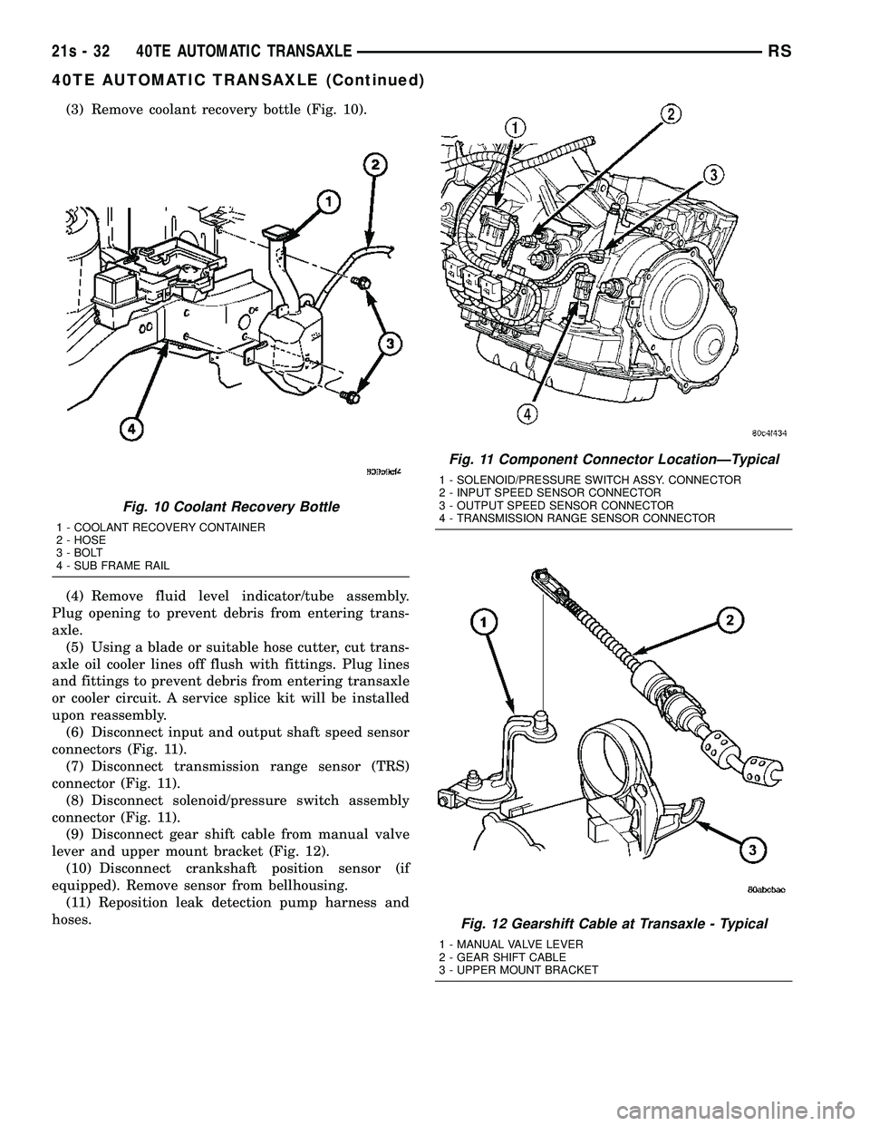
(3) Remove coolant recovery bottle (Fig. 10).
(4) Remove fluid level indicator/tube assembly.
Plug opening to prevent debris from entering trans-
axle. (5) Using a blade or suitable hose cutter, cut trans-
axle oil cooler lines off flush with fittings. Plug lines
and fittings to prevent debris from entering transaxle
or cooler circuit. A service splice kit will be installed
upon reassembly. (6) Disconnect input and output shaft speed sensor
connectors (Fig. 11). (7) Disconnect transmission range sensor (TRS)
connector (Fig. 11). (8) Disconnect solenoid/pressure switch assembly
connector (Fig. 11). (9) Disconnect gear shift cable from manual valve
lever and upper mount bracket (Fig. 12). (10) Disconnect crankshaft position sensor (if
equipped). Remove sensor from bellhousing. (11) Reposition leak detection pump harness and
hoses.
Fig. 10 Coolant Recovery Bottle
1 - COOLANT RECOVERY CONTAINER
2 - HOSE
3 - BOLT
4 - SUB FRAME RAIL
Fig. 11 Component Connector LocationÐTypical
1 - SOLENOID/PRESSURE SWITCH ASSY. CONNECTOR
2 - INPUT SPEED SENSOR CONNECTOR
3 - OUTPUT SPEED SENSOR CONNECTOR
4 - TRANSMISSION RANGE SENSOR CONNECTOR
Fig. 12 Gearshift Cable at Transaxle - Typical
1 - MANUAL VALVE LEVER
2 - GEAR SHIFT CABLE
3 - UPPER MOUNT BRACKET
21s - 32 40TE AUTOMATIC TRANSAXLERS
40TE AUTOMATIC TRANSAXLE (Continued)
Page 1927 of 2585
NOTE: The 2/4 Clutch Piston has bonded seals
which are not individually serviceable. Seal replace-
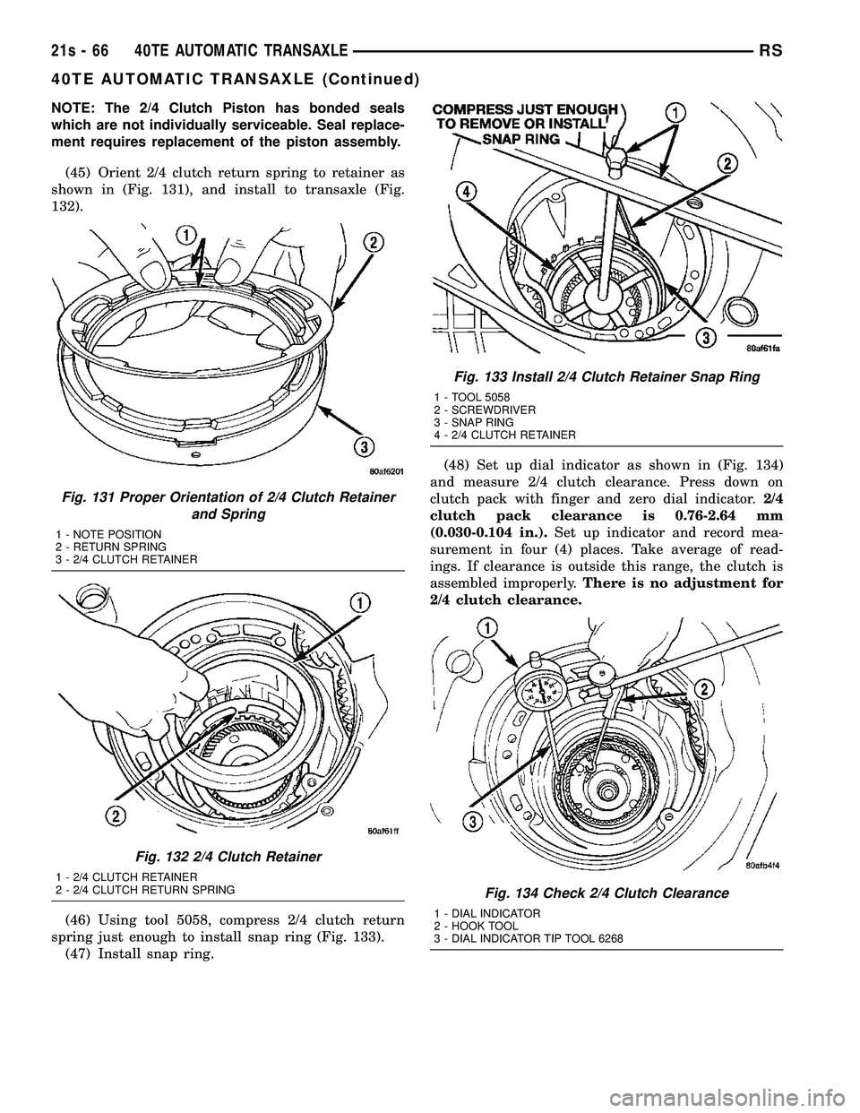
ment requires replacement of the piston assembly.(45) Orient 2/4 clutch return spring to retainer as
shown in (Fig. 131), and install to transaxle (Fig.
132).
(46) Using tool 5058, compress 2/4 clutch return
spring just enough to install snap ring (Fig. 133). (47) Install snap ring. (48) Set up dial indicator as shown in (Fig. 134)
and measure 2/4 clutch clearance. Press down on
clutch pack with finger and zero dial indicator. 2/4
clutch pack clearance is 0.76-2.64 mm
(0.030-0.104 in.). Set up indicator and record mea-
surement in four (4) places. Take average of read-
ings. If clearance is outside this range, the clutch is
assembled improperly. There is no adjustment for
2/4 clutch clearance.
Fig. 131 Proper Orientation of 2/4 Clutch Retainer and Spring
1 - NOTE POSITION
2 - RETURN SPRING
3 - 2/4 CLUTCH RETAINER
Fig. 132 2/4 Clutch Retainer
1 - 2/4 CLUTCH RETAINER
2 - 2/4 CLUTCH RETURN SPRING
Fig. 133 Install 2/4 Clutch Retainer Snap Ring
1 - TOOL 5058
2 - SCREWDRIVER
3 - SNAP RING
4 - 2/4 CLUTCH RETAINER
Fig. 134 Check 2/4 Clutch Clearance
1 - DIAL INDICATOR
2 - HOOK TOOL
3 - DIAL INDICATOR TIP TOOL 6268
21s - 66 40TE AUTOMATIC TRANSAXLERS
40TE AUTOMATIC TRANSAXLE (Continued)
Page 1935 of 2585
(13) Install left and right halfshaft assemblies.
(Refer t o 3 - DIFFERENTIAL & DRIVELINE/HALF
SHAFT - INSTALLATION) (14) Install front wheel/tire assemblies.
(15) Lower vehicle.
(16) Torque remaining rear mount bracket-to-tran-
saxle vertical bolts (Fig. 160) to 102 N´m (75 ft. lbs.). (17) Install transaxle upper bellhousing-to-block
bolts and torque to 95 N´m (70 ft. lbs.). (18) Install and connect crank position sensor (if
equipped). (19) Connect gearshift cable to upper mount
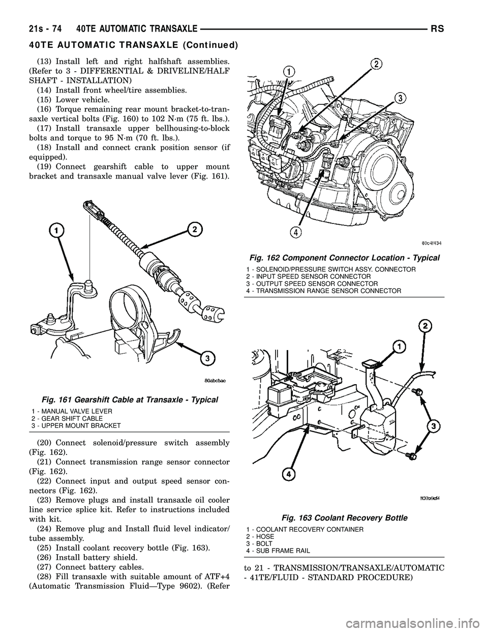
bracket and transaxle manual valve lever (Fig. 161).
(20) Connect solenoid/pressure switch assembly
(Fig. 162). (21) Connect transmission range sensor connector
(Fig. 162). (22) Connect input and output speed sensor con-
nectors (Fig. 162). (23) Remove plugs and install transaxle oil cooler
line service splice kit. Refer to instructions included
with kit. (24) Remove plug and Install fluid level indicator/
tube assembly. (25) Install coolant recovery bottle (Fig. 163).
(26) Install battery shield.
(27) Connect battery cables.
(28) Fill transaxle with suitable amount of ATF+4
(Automatic Transmission FluidÐType 9602). (Refer to 21 - TRANSMISSION/TRANSAXLE/AUTOMATIC
- 41TE/FLUID - STANDARD PROCEDURE)
Fig. 161 Gearshift Cable at Transaxle - Typical
1 - MANUAL VALVE LEVER
2 - GEAR SHIFT CABLE
3 - UPPER MOUNT BRACKET
Fig. 162 Component Connector Location - Typical
1 - SOLENOID/PRESSURE SWITCH ASSY. CONNECTOR
2 - INPUT SPEED SENSOR CONNECTOR
3 - OUTPUT SPEED SENSOR CONNECTOR
4 - TRANSMISSION RANGE SENSOR CONNECTOR
Fig. 163 Coolant Recovery Bottle
1 - COOLANT RECOVERY CONTAINER
2 - HOSE
3 - BOLT
4 - SUB FRAME RAIL
21s - 74 40TE AUTOMATIC TRANSAXLERS
40TE AUTOMATIC TRANSAXLE (Continued)