2004 CHRYSLER VOYAGER radiator cap
[x] Cancel search: radiator capPage 1396 of 2585
AIR CLEANER HOUSING
REMOVAL
(1) Disconnect the negative battery cable.
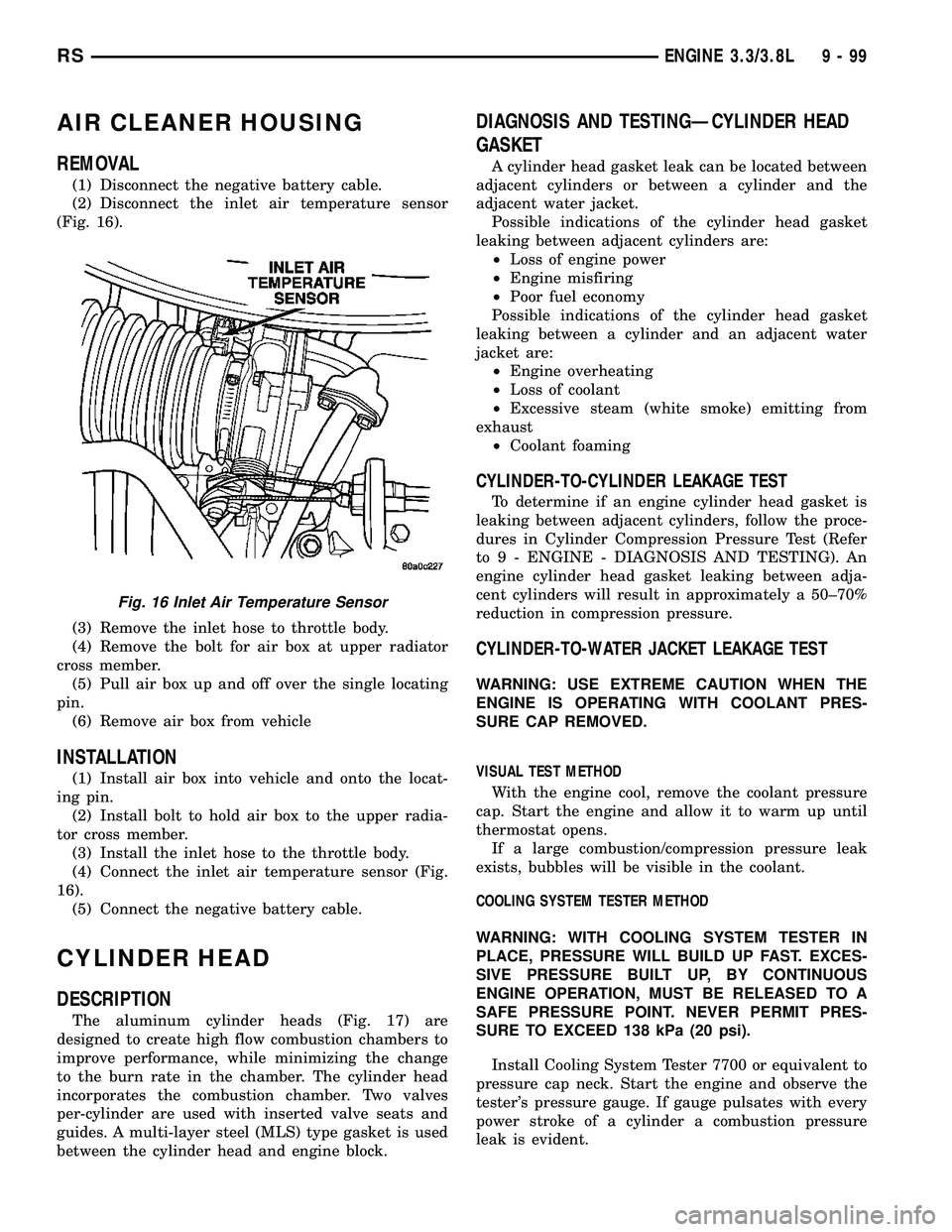
(2) Disconnect the inlet air temperature sensor
(Fig. 16).
(3) Remove the inlet hose to throttle body.
(4) Remove the bolt for air box at upper radiator
cross member.
(5) Pull air box up and off over the single locating
pin.
(6) Remove air box from vehicle
INSTALLATION
(1) Install air box into vehicle and onto the locat-
ing pin.
(2) Install bolt to hold air box to the upper radia-
tor cross member.
(3) Install the inlet hose to the throttle body.
(4) Connect the inlet air temperature sensor (Fig.
16).
(5) Connect the negative battery cable.
CYLINDER HEAD
DESCRIPTION
The aluminum cylinder heads (Fig. 17) are
designed to create high flow combustion chambers to
improve performance, while minimizing the change
to the burn rate in the chamber. The cylinder head
incorporates the combustion chamber. Two valves
per-cylinder are used with inserted valve seats and
guides. A multi-layer steel (MLS) type gasket is used
between the cylinder head and engine block.
DIAGNOSIS AND TESTINGÐCYLINDER HEAD
GASKET
A cylinder head gasket leak can be located between
adjacent cylinders or between a cylinder and the
adjacent water jacket.
Possible indications of the cylinder head gasket
leaking between adjacent cylinders are:
²Loss of engine power
²Engine misfiring
²Poor fuel economy
Possible indications of the cylinder head gasket
leaking between a cylinder and an adjacent water
jacket are:
²Engine overheating
²Loss of coolant
²Excessive steam (white smoke) emitting from
exhaust
²Coolant foaming
CYLINDER-TO-CYLINDER LEAKAGE TEST
To determine if an engine cylinder head gasket is
leaking between adjacent cylinders, follow the proce-
dures in Cylinder Compression Pressure Test (Refer
to 9 - ENGINE - DIAGNOSIS AND TESTING). An
engine cylinder head gasket leaking between adja-
cent cylinders will result in approximately a 50±70%
reduction in compression pressure.
CYLINDER-TO-WATER JACKET LEAKAGE TEST
WARNING: USE EXTREME CAUTION WHEN THE
ENGINE IS OPERATING WITH COOLANT PRES-
SURE CAP REMOVED.
VISUAL TEST METHOD
With the engine cool, remove the coolant pressure
cap. Start the engine and allow it to warm up until
thermostat opens.
If a large combustion/compression pressure leak
exists, bubbles will be visible in the coolant.
COOLING SYSTEM TESTER METHOD
WARNING: WITH COOLING SYSTEM TESTER IN
PLACE, PRESSURE WILL BUILD UP FAST. EXCES-
SIVE PRESSURE BUILT UP, BY CONTINUOUS
ENGINE OPERATION, MUST BE RELEASED TO A
SAFE PRESSURE POINT. NEVER PERMIT PRES-
SURE TO EXCEED 138 kPa (20 psi).
Install Cooling System Tester 7700 or equivalent to
pressure cap neck. Start the engine and observe the
tester's pressure gauge. If gauge pulsates with every
power stroke of a cylinder a combustion pressure
leak is evident.
Fig. 16 Inlet Air Temperature Sensor
RSENGINE 3.3/3.8L9-99
Page 1435 of 2585

OIL COOLER & LINES
DESCRIPTION
An engine oil cooler is used on 3.3/3.8L engines
(Heavy Duty Cooling Only) (Fig. 98). The cooler is a
coolant-to-oil type and mounted between the oil filter
and engine block.
OPERATION
Engine oil travels from the oil filter and into the
oil cooler. Engine oil then exits the cooler into the
main gallery. Engine coolant flows into the cooler
from the heater return tube and exits into the water
pump inlet.
REMOVAL
(1) Drain cooling system (Refer to 7 - COOLING -
STANDARD PROCEDURE - COOLING SYSTEM
DRAINING).
(2) Disconnect oil cooler inlet and outlet hoses
(Fig. 97).
(3) Remove oil filter.
(4) Remove oil cooler attachment fitting (Fig. 98).
(5) Remove oil cooler.
INSTALLATION
(1) Lubricate seal and position oil cooler to connec-
tor fitting on oil filter adapter (Fig. 98).NOTE: Position the flat side of oil cooler parallel to
oil pan rail.
(2) Install oil cooler attachment fitting and tighten
to 27 N´m (20 ft. lbs.) (Fig. 98).
(3) Install oil filter.
(4) Connect oil cooler inlet and outlet hoses (Fig.
97).
Fig. 96 Engine Oil Level Dipstick and Fill Locations
1 - COOLANT RECOVERY CONTAINER 3 - ENGINE OIL LEVEL DIPSTICK
2 - ENGINE OIL FILL CAP 4 - RADIATOR PRESSURE CAP
Fig. 97 Engine Oil Cooler Hoses
1 - OIL COOLER INLET TUBE
2 - INLET HOSE
3 - OIL COOLER OUTLET TUBE
4 - OUTLET HOSE
5 - WATER PUMP INLET TUBE
9 - 138 ENGINE 3.3/3.8LRS
OIL (Continued)
Page 2396 of 2585
HEATING & AIR CONDITIONING
TABLE OF CONTENTS
page page
HEATING & AIR CONDITIONING
DESCRIPTION
DESCRIPTION - ENGINE COOLING
SYSTEM REQUIREMENTS...............1
DESCRIPTION - HEATER AND AIR
CONDITIONER........................1
DESCRIPTION - SINGLE ZONE...........2
DESCRIPTION - DUAL ZONE.............2
DESCRIPTION - MANUAL THREE ZONE.....2
DESCRIPTION - AUTOMATIC THREE ZONE . . 3
OPERATION
OPERATION - HEATER AND AIR
CONDITIONER........................4
OPERATION - SINGLE ZONE.............4
OPERATION - DUAL ZONE...............5
OPERATION - MANUAL THREE ZONE......5
OPERATION - THREE ZONE ATC..........5DIAGNOSIS AND TESTING
DIAGNOSIS AND TESTING - A/C COOL
DOWN TEST..........................6
DIAGNOSIS AND TESTING - A/C
PERFORMANCE TEST..................7
DIAGNOSIS AND TESTING - HEATER
PERFORMANCE TEST.................10
SPECIFICATIONS
A/C SYSTEM.........................11
CONTROLS - FRONT.....................14
CONTROLS - REAR......................34
DISTRIBUTION - FRONT...................43
DISTRIBUTION - REAR....................56
PLUMBING - FRONT.....................64
PLUMBING - REAR......................97
CABIN HEATER........................112
HEATING & AIR
CONDITIONING
DESCRIPTION
DESCRIPTION - ENGINE COOLING SYSTEM
REQUIREMENTS
To maintain the performance level of the heating,
ventilation and air conditioning (HVAC) system, the
engine cooling system must be properly maintained.
The use of a bug screen is not recommended. Any
obstructions in front of the radiator or condenser will
reduce the performance of the air conditioning and
engine cooling systems.
The engine cooling system includes the radiator,
thermostat, radiator hoses and the engine coolant
pump. Refer to Cooling for more information before
opening or attempting any service to the engine cool-
ing system.
DESCRIPTION - HEATER AND AIR
CONDITIONER
A manually controlled single zone type heating-air
conditioning system, manually controlled dual zone
type heating-air conditioning system, manually con-
trolled three zone type heating-air conditioning sys-
tem or an automatic controlled three zone typeheating-air conditioning system is available on this
model.
All vehicles are equipped with a common heater,
ventilation and air conditioning (HVAC) housing (Fig.
1). The system combines air conditioning, heating,
and ventilating capabilities in a single unit housing
mounted within the passenger compartment under
the instrument panel. The HVAC housing includes:
²Blower motor
²Blower motor resistor block or power module
(depending on application)
²Heater core
²Evaporator coil
²Blend door and actuator
²Mode door and actuator
²Recirculation door and actuator
Based upon the system and mode selected, condi-
tioned air can exit the HVAC housing through one or
a combination of the three main housing outlets:
defrost, panel or floor. The defrost and panel outlets
are located on the top of the housing and the floor
outlet is located on the bottom of the housing. Once
the conditioned air exits the unit housing, it is fur-
ther directed through molded plastic ducts to the var-
ious outlets in the vehicle interior. These outlets and
their locations are as follows:
²Defroster Outlet- A single large defroster out-
let is located in the center of the instrument panel
top cover, near the base of the windshield.
²Side Window Demister Outlets- There are
two side window demister outlets, one is located at
RSHEATING & AIR CONDITIONING24-1
Page 2405 of 2585
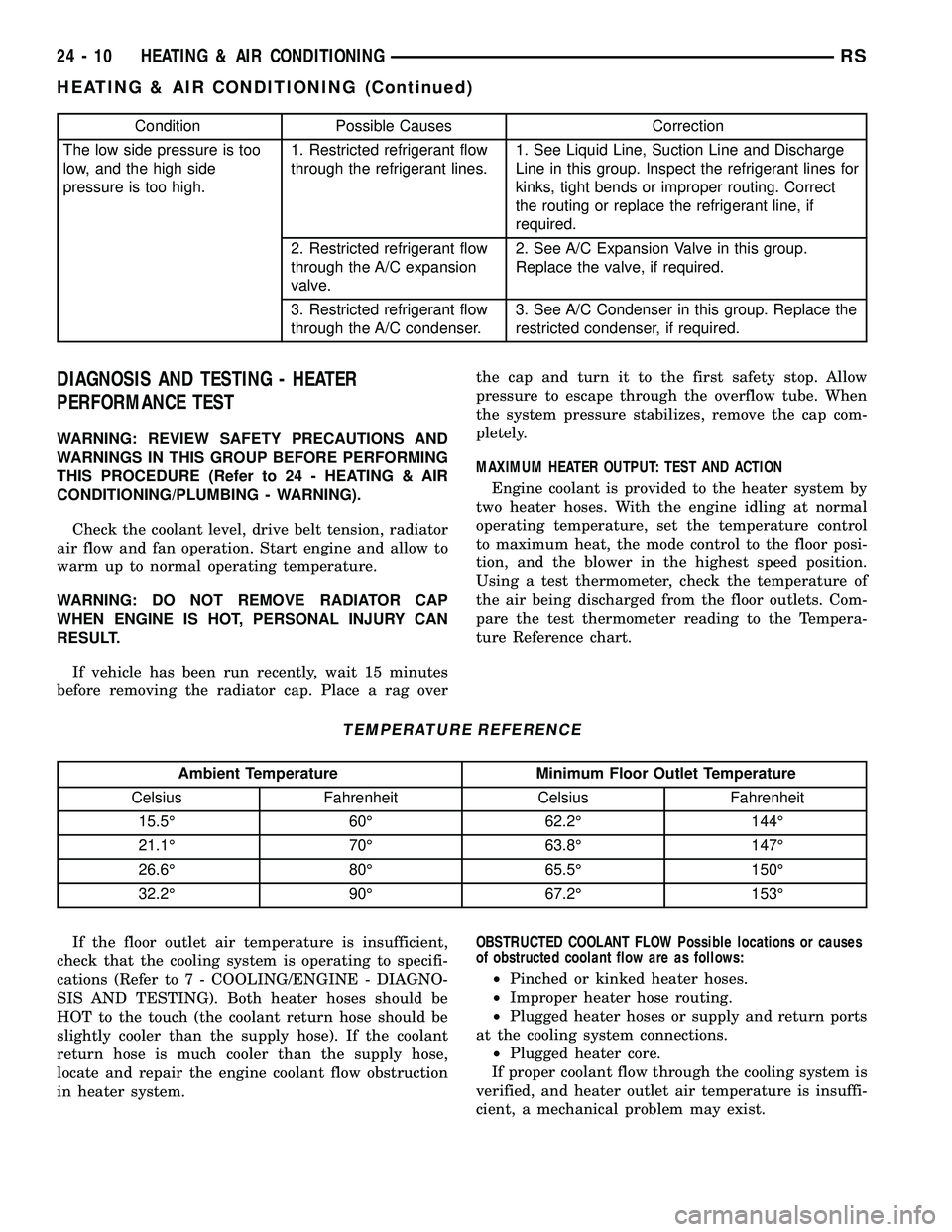
Condition Possible Causes Correction
The low side pressure is too
low, and the high side
pressure is too high.1. Restricted refrigerant flow
through the refrigerant lines.1. See Liquid Line, Suction Line and Discharge
Line in this group. Inspect the refrigerant lines for
kinks, tight bends or improper routing. Correct
the routing or replace the refrigerant line, if
required.
2. Restricted refrigerant flow
through the A/C expansion
valve.2. See A/C Expansion Valve in this group.
Replace the valve, if required.
3. Restricted refrigerant flow
through the A/C condenser.3. See A/C Condenser in this group. Replace the
restricted condenser, if required.
DIAGNOSIS AND TESTING - HEATER
PERFORMANCE TEST
WARNING: REVIEW SAFETY PRECAUTIONS AND
WARNINGS IN THIS GROUP BEFORE PERFORMING
THIS PROCEDURE (Refer to 24 - HEATING & AIR
CONDITIONING/PLUMBING - WARNING).
Check the coolant level, drive belt tension, radiator
air flow and fan operation. Start engine and allow to
warm up to normal operating temperature.
WARNING: DO NOT REMOVE RADIATOR CAP
WHEN ENGINE IS HOT, PERSONAL INJURY CAN
RESULT.
If vehicle has been run recently, wait 15 minutes
before removing the radiator cap. Place a rag overthe cap and turn it to the first safety stop. Allow
pressure to escape through the overflow tube. When
the system pressure stabilizes, remove the cap com-
pletely.
MAXIMUM HEATER OUTPUT: TEST AND ACTION
Engine coolant is provided to the heater system by
two heater hoses. With the engine idling at normal
operating temperature, set the temperature control
to maximum heat, the mode control to the floor posi-
tion, and the blower in the highest speed position.
Using a test thermometer, check the temperature of
the air being discharged from the floor outlets. Com-
pare the test thermometer reading to the Tempera-
ture Reference chart.
TEMPERATURE REFERENCE
Ambient Temperature Minimum Floor Outlet Temperature
Celsius Fahrenheit Celsius Fahrenheit
15.5É 60É 62.2É 144É
21.1É 70É 63.8É 147É
26.6É 80É 65.5É 150É
32.2É 90É 67.2É 153É
If the floor outlet air temperature is insufficient,
check that the cooling system is operating to specifi-
cations (Refer to 7 - COOLING/ENGINE - DIAGNO-
SIS AND TESTING). Both heater hoses should be
HOT to the touch (the coolant return hose should be
slightly cooler than the supply hose). If the coolant
return hose is much cooler than the supply hose,
locate and repair the engine coolant flow obstruction
in heater system.OBSTRUCTED COOLANT FLOW Possible locations or causes
of obstructed coolant flow are as follows:
²Pinched or kinked heater hoses.
²Improper heater hose routing.
²Plugged heater hoses or supply and return ports
at the cooling system connections.
²Plugged heater core.
If proper coolant flow through the cooling system is
verified, and heater outlet air temperature is insuffi-
cient, a mechanical problem may exist.
24 - 10 HEATING & AIR CONDITIONINGRS
HEATING & AIR CONDITIONING (Continued)
Page 2460 of 2585
SERVICE PORT VALVE CORE
DESCRIPTION.........................94
REMOVAL.............................94
INSTALLATION.........................94SUCTION LINE
REMOVAL.............................94
INSTALLATION.........................95
PLUMBING - FRONT
DESCRIPTION - REFRIGERANT LINE
The refrigerant lines and hoses are used to carry
the refrigerant between the various air conditioning
system components. A barrier hose design with a
nylon tube, which is sandwiched between rubber lay-
ers, is used for the R-134a air conditioning system on
this vehicle. This nylon tube helps to further contain
the R-134a refrigerant, which has a smaller molecu-
lar structure than R-12 refrigerant. The ends of the
refrigerant hoses are made from lightweight alumi-
num or steel, and commonly use braze-less fittings.
Any kinks or sharp bends in the refrigerant plumb-
ing will reduce the capacity of the entire air condi-
tioning system. Kinks and sharp bends reduce the
flow of refrigerant in the system. A good rule for the
flexible hose refrigerant lines is to keep the radius of
all bends at least ten times the diameter of the hose.
In addition, the flexible hose refrigerant lines should
be routed so they are at least 80 millimeters (3
inches) from an exhaust manifold.
OPERATION- REFRIGERANT LINES
High pressures are produced in the refrigerant sys-
tem when the air conditioning compressor is operat-
ing. Extreme care must be exercised to make sure
that each of the refrigerant system connections is
pressure-tight and leak free. It is a good practice to
inspect all flexible hose refrigerant lines at least once
a year to make sure they are in good condition and
properly routed.
The refrigerant lines and hoses are coupled with
other components of the HVAC system with either
O-rings or dual plane seals.
The refrigerant lines and hoses cannot be repaired
and, if faulty or damaged, they must be replaced.
WARNING
ENGINE COOLING SYSTEM
WARNING: THE ENGINE COOLING SYSTEM IS
DESIGNED TO DEVELOP INTERNAL PRESSURES
OF 97 TO 123 KILOPASCALS (14 TO 18 POUNDS
PER SQUARE INCH). DO NOT REMOVE OR
LOOSEN THE COOLANT PRESSURE CAP, CYLIN-
DER BLOCK DRAIN PLUGS, RADIATOR DRAIN,
RADIATOR HOSES, HEATER HOSES, OR HOSE
CLAMPS WHILE THE ENGINE COOLING SYSTEM ISHOT AND UNDER PRESSURE. FAILURE TO
OBSERVE THIS WARNING CAN RESULT IN SERI-
OUS BURNS FROM THE HEATED ENGINE COOL-
ANT. ALLOW THE VEHICLE TO COOL FOR A
MINIMUM OF 15 MINUTES BEFORE OPENING THE
COOLING SYSTEM FOR SERVICE.
A/C SYSTEM
WARNING: THE AIR CONDITIONING SYSTEM CON-
TAINS REFRIGERANT UNDER HIGH PRESSURE.
SEVERE PERSONAL INJURY MAY RESULT FROM
IMPROPER SERVICE PROCEDURES. REPAIRS
SHOULD ONLY BE PERFORMED BY QUALIFIED
SERVICE PERSONNEL.
AVOID BREATHING THE REFRIGERANT AND
REFRIGERANT OIL VAPOR OR MIST. EXPOSURE
MAY IRRITATE THE EYES, NOSE, AND/OR THROAT.
WEAR EYE PROTECTION WHEN SERVICING THE
AIR CONDITIONING REFRIGERANT SYSTEM. SERI-
OUS EYE INJURY CAN RESULT FROM DIRECT
CONTACT WITH THE REFRIGERANT. IF EYE CON-
TACT OCCURS, SEEK MEDICAL ATTENTION IMME-
DIATELY.
DO NOT EXPOSE THE REFRIGERANT TO OPEN
FLAME. POISONOUS GAS IS CREATED WHEN
REFRIGERANT IS BURNED. AN ELECTRONIC LEAK
DETECTOR IS RECOMMENDED.
IF ACCIDENTAL SYSTEM DISCHARGE OCCURS,
VENTILATE THE WORK AREA BEFORE RESUMING
SERVICE. LARGE AMOUNTS OF REFRIGERANT
RELEASED IN A CLOSED WORK AREA WILL DIS-
PLACE THE OXYGEN AND CAUSE SUFFOCATION.
THE EVAPORATION RATE OF R-134a REFRIGER-
ANT AT AVERAGE TEMPERATURE AND ALTITUDE
IS EXTREMELY HIGH. AS A RESULT, ANYTHING
THAT COMES IN CONTACT WITH THE REFRIGER-
ANT WILL FREEZE. ALWAYS PROTECT THE SKIN
OR DELICATE OBJECTS FROM DIRECT CONTACT
WITH THE REFRIGERANT.
THE R-134a SERVICE EQUIPMENT OR THE VEHI-
CLE REFRIGERANT SYSTEM SHOULD NOT BE
PRESSURE TESTED OR LEAK TESTED WITH COM-
PRESSED AIR. SOME MIXTURES OF AIR AND
R-134a HAVE BEEN SHOWN TO BE COMBUSTIBLE
AT ELEVATED PRESSURES. THESE MIXTURES ARE
POTENTIALLY DANGEROUS, AND MAY RESULT IN
FIRE OR EXPLOSION CAUSING INJURY OR PROP-
ERTY DAMAGE.
RSPLUMBING - FRONT24-65
Page 2475 of 2585
INSTALLATION
(1) Position the discharge line into the engine com-
partment.
(2) Remove the tape or plugs from the compressor
discharge port and the discharge line fitting.
(3) Lubricate a new rubber O-ring seal with clean
refrigerant oil and install it on the discharge line fit-
ting.
(4) Install a new dual plane seal and reconnect the
discharge line fitting to the compressor discharge
port on the top of the compressor.
(5) Install the nut that secures the discharge line
fitting to the compressor. Tighten the nut to 23 N´m
(17 ft. lbs.).
(6) Remove the tape or plugs from the condenser
inlet port and the discharge line fitting.
(7) Lubricate a new rubber O-ring seal with clean
refrigerant oil and install it on the discharge line fit-
ting.
(8) Install a new dual plane seal and reconnect the
discharge line fitting to the condenser inlet port on
the right side of the cooling module.
(9) Install the nut that secures the discharge line
fitting to the condenser. Tighten the nut to 23 N´m
(17 ft. lbs.).
(10) Position the radiator sight shield onto the
radiator closure panel crossmember.
(11) Install the five small screws that secure the
front fascia grille inserts to the radiator sight shield.
Tighten the screws to 2 N´m (17 in. lbs.).
(12) Install and tighten the two large screws that
secure the front fascia and the outboard ends of the
radiator sight shield to the radiator closure panel
crossmember. Tighten the screws to 6 N´m (53 in.
lbs.).
(13) Evacuate the refrigerant system (Refer to 24 -
HEATING & AIR CONDITIONING/PLUMBING -
FRONT/REFRIGERANT - STANDARD PROCE-
DURE - REFRIGERANT SYSTEM EVACUATE).
(14) Charge the refrigerant system (Refer to 24 -
HEATING & AIR CONDITIONING/PLUMBING -
FRONT/REFRIGERANT - STANDARD PROCE-
DURE - REFRIGERANT SYSTEM CHARGE).
A/C EVAPORATOR
DESCRIPTION
The A/C evaporator is located in the HVAC hous-
ing, behind the instrument panel. The evaporator is
positioned in the housing so that all air that enters
the housing must pass over the fins of the evaporator
coils before it is distributed through the system ducts
and outlets. However, air passing over the evaporator
fins will only be conditioned when the compressor isengaged and circulating refrigerant through the
evaporator tubes.
OPERATION
Refrigerant enters the A/C evaporator from the
expansion valve as a low-temperature, low-pressure
liquid. As air flows over the fins of the evaporator,
the humidity in the air condenses on the fins, and
the heat from the air is absorbed by the refrigerant.
Heat absorption causes the refrigerant to boil and
vaporize. The refrigerant becomes a low-pressure gas
when it leaves the evaporator.
The A/C evaporator cannot be repaired and, if
faulty or damaged, it must be replaced.
REMOVAL
WARNING: ON VEHICLES EQUIPPED WITH AIR-
BAGS, DISABLE THE AIRBAG SYSTEM BEFORE
ATTEMPTING ANY STEERING WHEEL, STEERING
COLUMN, OR INSTRUMENT PANEL COMPONENT
DIAGNOSIS OR SERVICE. DISCONNECT AND ISO-
LATE THE BATTERY NEGATIVE (GROUND) CABLE,
THEN WAIT TWO MINUTES FOR THE AIRBAG SYS-
TEM CAPACITOR TO DISCHARGE BEFORE PER-
FORMING FURTHER DIAGNOSIS OR SERVICE. THIS
IS THE ONLY SURE WAY TO DISABLE THE AIRBAG
SYSTEM. FAILURE TO TAKE THE PROPER PRE-
CAUTIONS COULD RESULT IN ACCIDENTAL AIR-
BAG DEPLOYMENT AND POSSIBLE PERSONAL
INJURY.
(1) Remove the HVAC housing (Refer to 24 -
HEATING & AIR CONDITIONING/DISTRIBUTION/
HVAC HOUSING - REMOVAL).
(2) Disassemble the HVAC housing to access the
evaporator (Refer to 24 - HEATING & AIR CONDI-
TIONING/DISTRIBUTION/HVAC HOUSING - DIS-
ASSEMBLY).
(3) Carefully lift the evaporator and its foam wrap
out of the lower half of the HVAC housing as a unit.
Be certain not to lose the clam shell type rubber seal
that is fitted to the evaporator inlet and outlet tubes
where they exit the HVAC housing.
INSTALLATION
NOTE: If the evaporator is being replaced, add 50
milliliters (1.8 fluid ounces) of refrigerant oil to the
refrigerant system. Use only refrigerant oil of the
type recommended for the compressor in the vehi-
cle.
(1) Carefully lower the evaporator and its foam
wrap into the lower half of the HVAC housing as a
unit. Be certain that the clam shell type rubber seal
24 - 80 PLUMBING - FRONTRS
A/C DISCHARGE LINE (Continued)
Page 2496 of 2585
(4) Install the two screws that secure the rear A/C
expansion valve to the evaporator tube sealing plate.
Tighten the screws to 11 N´m (97 in. lbs.).
(5) Install the rear evaporator line extension onto
the expansion valve (Refer to 24 - HEATING & AIR
CONDITIONING/PLUMBING - REAR/EVAPORA-
TOR - INSTALLATION - EVAPORATOR LINE
EXTENSION).
(6) Install the foam insulator wrap over the rear
expansion valve.
(7) Install the rear HVAC housing (Refer to 24 -
HEATING & AIR CONDITIONING/DISTRIBUTION/
HVAC HOUSING - INSTALLATION).
(8) Run the HVAC Cooldown Test to verify proper
operation.
HEATER CORE
DESCRIPTION
The rear heater core is located near the front of
the rear HVAC housing, behind the right rear wheel
house. It is a heat exchanger made of rows of tubes
and fins. One end of the core is fitted with a molded
plastic tank that includes integral heater core inlet
and outlet nipples. The rear heater core can be ser-
viced without removing the rear HVAC housing from
the vehicle.
OPERATION
Engine coolant is circulated through underbody
heater hoses to the rear heater core at all times. As
the coolant flows through the rear heater core, heat
removed from the engine is transferred to the heater
core fins and tubes. Air directed through the heater
core picks up the heat from the heater core fins. The
rear blend door allows control of the rear heater out-
put air temperature by controlling how much of the
air flowing through the rear HVAC housing is
directed through the heater core.
The rear heater core cannot be repaired and, if
faulty or damaged, it must be replaced.
STANDARD PROCEDURE - REAR HEATER
CORE FILLING
In its final installed position, the rear heater core
is positioned higher than the radiator fill cap. There-
fore, when the cooling system is drained and refilled,
gravity will not refill the heater core with coolant to
the proper level. This may result in two problems:1.
Insufficient coolant level in the engine cooling sys-
tem, which may result in engine overheating.2.Air
entrapped within the rear heater core, which may
result in insufficient rear heater performance. There
are two methods that may be employed to prevent
these problems:1.Pre-filling of the rear heater core.2.Thermal cycling of the engine cooling system. Fol-
lowing are descriptions of both prevention methods,
as well as a method to verify rear heater perfor-
mance.
WARNING: REFER TO THE APPLICABLE WARN-
INGS AND CAUTIONS FOR THIS SYSTEM BEFORE
PERFORMING THE FOLLOWING OPERATION (Refer
to 24 - HEATING & AIR CONDITIONING/PLUMBING
FRONT - WARNING - HEATER PLUMBING).
PRE-FILLING
If the rear heater core or the rear HVAC housing
have been removed from the vehicle for service, the
rear heater core may be pre-filled with the proper
engine coolant mixture prior to reconnecting the
heater hoses to the heater core hose fittings.
(1) The heater core should be installed in the rear
HVAC housing, and the rear HVAC housing should
be installed in the vehicle.
(2) Take the proper precautions to protect the car-
peting below the rear heater core from spilled engine
coolant and have absorbent toweling readily avail-
able to mop up any spills.
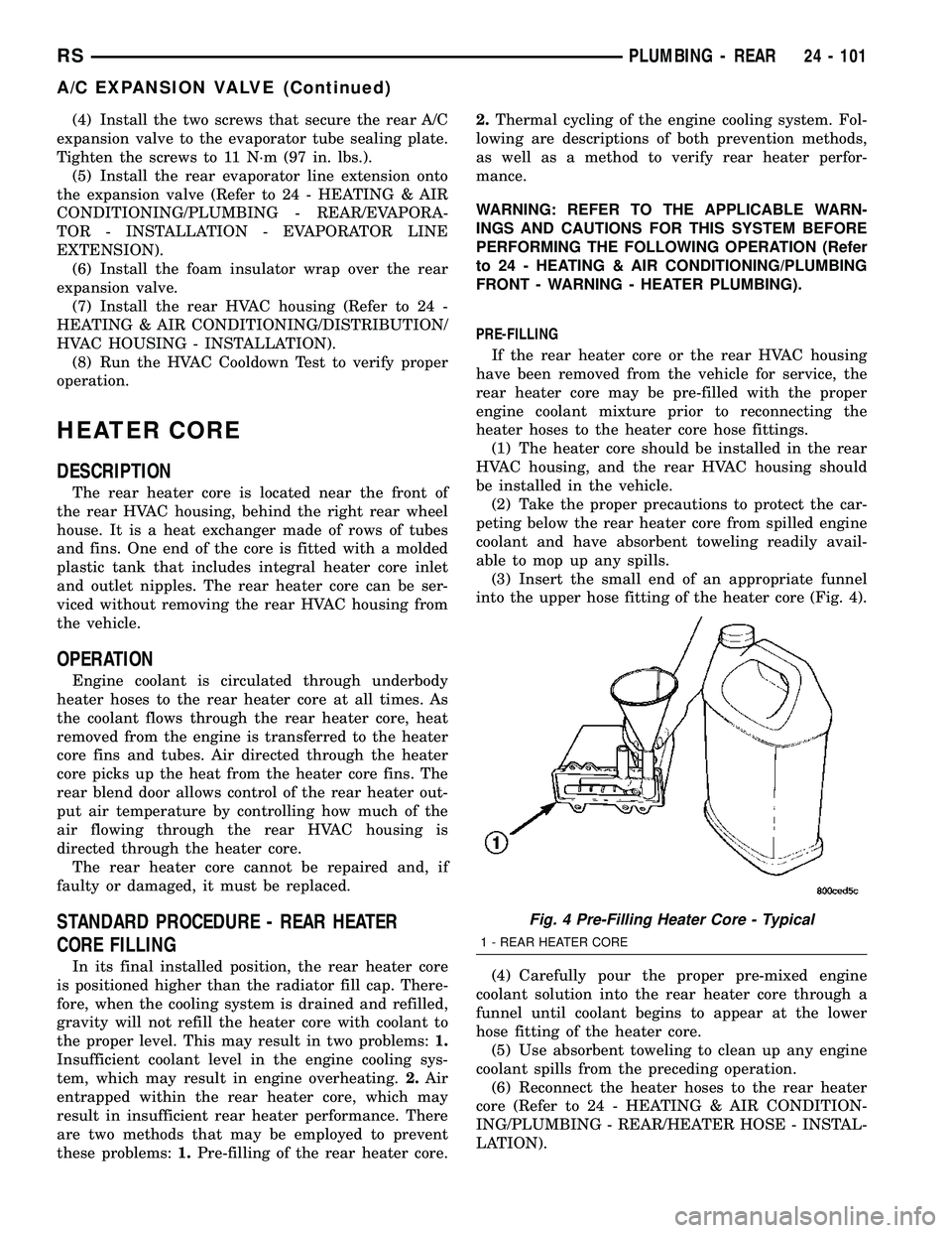
(3) Insert the small end of an appropriate funnel
into the upper hose fitting of the heater core (Fig. 4).
(4) Carefully pour the proper pre-mixed engine
coolant solution into the rear heater core through a
funnel until coolant begins to appear at the lower
hose fitting of the heater core.
(5) Use absorbent toweling to clean up any engine
coolant spills from the preceding operation.
(6) Reconnect the heater hoses to the rear heater
core (Refer to 24 - HEATING & AIR CONDITION-
ING/PLUMBING - REAR/HEATER HOSE - INSTAL-
LATION).
Fig. 4 Pre-Filling Heater Core - Typical
1 - REAR HEATER CORE
RSPLUMBING - REAR24 - 101
A/C EXPANSION VALVE (Continued)
Page 2549 of 2585
CABLE - DIAGNOSIS AND TESTING,
ANTENNA BODY......................8A-4
CABLE - DIAGNOSIS AND TESTING,
BATTERY...........................8F-16
CABLE - INSTALLATION................8P-4
CABLE - INSTALLATION, ANTENNA BODY . . 8A-6
CABLE - INSTALLATION, FRONT.....5-64,5s-67
CABLE - INSTALLATION, GEAR SHIFT....21-205
CABLE - INSTALLATION, HOLD OPEN
LATCH .............................23-38
CABLE - INSTALLATION, INSIDE HANDLE . . 23-38
CABLE - INSTALLATION, INSTRUMENT
PANEL ANTENNA......................8A-9
CABLE - INSTALLATION, LATCH RELEASE . 23-62
CABLE - INSTALLATION, OUTSIDE
HANDLE............................23-37
CABLE - INSTALLATION, PARKING
BRAKE LEVER AND FRONT.........5-66,5s-69
CABLE - INSTALLATION, THROTTLE
CONTROL..........................14-36
CABLE - OPERATION...................8P-4
CABLE - OPERATION, ANTENNA BODY.....8A-4
CABLE - REMOVAL....................8P-4
CABLE - REMOVAL, ANTENNA BODY......8A-5
CABLE - REMOVAL, FRONT.........5-64,5s-67
CABLE - REMOVAL, GEAR SHIFT.......21-204,
21s-105
CABLE - REMOVAL, HOLD OPEN LATCH . . . 23-38
CABLE - REMOVAL, INSIDE HANDLE.....23-37
CABLE - REMOVAL, INSTRUMENT PANEL
ANTENNA...........................8A-8
CABLE - REMOVAL, LATCH RELEASE.....23-61
CABLE - REMOVAL, OUTSIDE HANDLE....23-37
CABLE - REMOVAL, PARKING BRAKE
LEVER AND FRONT...............5-65,5s-68
CABLE - REMOVAL, THROTTLE
CONTROL..........................14-35
CABLE - SELECTOR - INSTALLATION,
GEARSHIFT.........................21-84
CABLE - SELECTOR - REMOVAL,
GEARSHIFT.........................21-81
CABLE ADJUSTMENT, ADJUSTMENTS -
GEARSHIFT........................21-206
CABLE ADJUSTMENT, INSTALLATION -
SYNCHRONIZING...............23-102,23-88
CABLE (FRONT) - INSTALLATION,
PARKING BRAKE.................5-63,5s-65
CABLE (FRONT) - REMOVAL, PARKING
BRAKE.........................5-59,5s-62
CABLE (INTERMEDIATE) -
INSTALLATION, PARKING BRAKE
....5-63,5s-66
CABLE (INTERMEDIATE) - REMOVAL,
PARKING BRAKE
.................5-60,5s-62
CABLE (LEFT REAR) - INSTALLATION,
PARKING BRAKE
.................5-64,5s-66
CABLE (LEFT REAR) - REMOVAL,
PARKING BRAKE
.................5-62,5s-64
CABLE RESISTANCE, SPECIFICATIONS -
SPARK PLUG
.........................8I-2
CABLE (RIGHT REAR) - INSTALLATION,
PARKING BRAKE
.................5-63,5s-66
CABLE (RIGHT REAR) - REMOVAL,
PARKING BRAKE
.................5-60,5s-63
CABLES - ADJUSTMENT, PARKING
BRAKE
.........................5-64,5s-66
CABLES - DESCRIPTION, BATTERY
.......8F-16
CABLES - INSTALLATION, BATTERY
......8F-18
CABLES - OPERATION, BATTERY
........8F-16
CABLES - REMOVAL, BATTERY
..........8F-18
CALIBRATION - STANDARD PROCEDURE,
A/C-HEATER CONTROL
................24-20
CALIBRATION - STANDARD PROCEDURE,
COMPASS
...........................8M-3
CALIPER - CLEANING
....5-25,5-29,5s-24,5s-28
CALIPER - INSPECTION
. . . 5-25,5-29,5s-24,5s-28
CALIPER - INSTALLATION, REAR DISC
BRAKE
.........................5-30,5s-29
CALIPER - REMOVAL, REAR DISC
BRAKE
.........................5-27,5s-26
CALIPER ADAPTER - INSTALLATION,
FRONT DISC BRAKE
..............5-31,5s-30
CALIPER ADAPTER - REMOVAL, FRONT
DISC BRAKE
....................5-31,5s-30
CALIPER (CONTINENTAL TEVES
BRAKES) - INSTALLATION, FRONT
DISC BRAKE
........................5s-26CALIPER (CONTINENTAL TEVES
BRAKES) - REMOVAL, FRONT DISC
BRAKE.............................5s-23
CALIPER (DISC/DISC BRAKES) -
INSTALLATION, FRONT DISC BRAKE......5-27
CALIPER (DISC/DISC BRAKES) -
REMOVAL, FRONT DISC BRAKE..........5-24
CALIPER (DISC/DRUM BRAKES) -
INSTALLATION, FRONT DISC BRAKE......5-27
CALIPER (DISC/DRUM BRAKES) -
REMOVAL, FRONT DISC BRAKE..........5-24
CALIPER GUIDE PIN BUSHINGS
(CONTINENTAL TEVES BRAKES) -
ASSEMBLY..........................5s-24
CALIPER GUIDE PIN BUSHINGS
(CONTINENTAL TEVES BRAKES) -
DISASSEMBLY.......................5s-23
CALIPER GUIDE PIN BUSHINGS
(DISC/DISC BRAKES) - ASSEMBLY........5-25
CALIPER GUIDE PIN BUSHINGS
(DISC/DISC BRAKES) - DISASSEMBLY.....5-24
CALIPER GUIDE PINS (DISC/DRUM
BRAKES) - INSTALLATION, DISC
BRAKE..............................5-31
CALIPER GUIDE PINS (DISC/DRUM
BRAKES) - REMOVAL, DISC BRAKE.......5-31
CALIPER GUIDE PINS (TRW BRAKES) -
INSTALLATION, DISC BRAKE............5s-30
CALIPER GUIDE PINS (TRW BRAKES) -
REMOVAL, DISC BRAKE...............5s-30
CALIPER PISTON AND SEAL -
ASSEMBLY.............5-26,5-29,5s-25,5s-28
CALIPER PISTON AND SEAL -
DISASSEMBLY..........5-24,5-28,5s-23,5s-27
CALIPER (TRW BRAKES) -
INSTALLATION, FRONT DISC BRAKE......5s-26
CALIPER (TRW BRAKES) - REMOVAL,
FRONT DISC BRAKE..................5s-23
CAMSHAFT & BEARINGS (IN BLOCK) -
DESCRIPTION.......................9-115
CAMSHAFT & BEARINGS (IN BLOCK) -
INSPECTION........................9-115
CAMSHAFT & BEARINGS (IN BLOCK) -
INSTALLATION.......................9-115
CAMSHAFT & BEARINGS (IN BLOCK) -
OPERATION.........................9-115
CAMSHAFT & BEARINGS (IN BLOCK) -
REMOVAL..........................9-115
CAMSHAFT END PLAY - STANDARD
PROCEDURE, MEASURING..............9-29
CAMSHAFT OIL SEAL(S) - INSTALLATION . . 9-28
CAMSHAFT OIL SEAL(S) - REMOVAL......9-27
CAMSHAFT POSITION SENSOR -
DESCRIPTION.........................8I-4
CAMSHAFT POSITION SENSOR -
OPERATION..........................8I-4
CAMSHAFT SPROCKET - INSTALLATION,
TIMING CHAIN.......................9-157
CAMSHAFT SPROCKET - REMOVAL,
TIMING CHAIN.......................9-156
CAMSHAFT SPROCKETS - INSTALLATION . . 9-65
CAMSHAFT SPROCKETS - REMOVAL......9-64
CAMSHAFT(S) - CLEANING..............9-29
CAMSHAFT(S) - DESCRIPTION...........9-28
CAMSHAFT(S) - INSPECTION............9-30
CAMSHAFT(S) - INSTALLATION..........9-30
CAMSHAFT(S) - OPERATION.............9-28
CAMSHAFT(S) - REMOVAL..............9-29
CANISTER - DESCRIPTION, VAPOR......25-18
CANISTER - INSTALLATION, REAR EVAP . . 25-20
CANISTER - OPERATION, VAPOR........25-18
CANISTER - REMOVAL, REAR EVAP......25-19
CAP - DESCRIPTION, FUEL FILLER.......25-12
CAP - DESCRIPTION, RADIATOR
PRESSURE..........................7-26
CAP - INSTALLATION, INSTRUMENT
PANEL END.........................23-68
CAP - OPERATION, FUEL FILLER........25-12
CAP - OPERATION, RADIATOR
PRESSURE
..........................7-27
CAP - REMOVAL, INSTRUMENT PANEL
END
...............................23-68
CAP TESTING - DIAGNOSIS AND
TESTING, COOLING SYSTEM
PRESSURE
..........................7-27
CAP TO FILLER NECK SEAL -
DIAGNOSIS AND TESTING, RADIATOR
.....7-27
CAPACITIES - SPECIFICATIONS, FLUID
......0-6CARE - CLEANING, ALUMINUM WHEEL . . . 22-18
CARGO - INSTALLATION, AWD, HEAVY
DUTY...............................2-36
CARGO - INSTALLATION, SPRING........2-40
CARGO - REMOVAL, AWD, HEAVY DUTY . . . 2-36
CARGO - REMOVAL, SPRING............2-40
CARPETS AND FLOOR MATS -
INSTALLATION.......................23-76
CARPETS AND FLOOR MATS - REMOVAL . 23-75
CARRIER ASSEMBLY - DESCRIPTION,
BALANCE SHAFTS.....................9-69
CARRIER ASSEMBLY - INSTALLATION,
BALANCE SHAFTS.....................9-72
CARRIER ASSEMBLY - OPERATION,
BALANCE SHAFTS.....................9-69
CARRIER ASSEMBLY - REMOVAL,
BALANCE SHAFTS.....................9-69
CARRIER SEAL - INSTALLATION,
DIFFERENTIAL........................21-9
CARRIER SEAL - REMOVAL,
DIFFERENTIAL........................21-9
CATALYTIC CONVERTER - DESCRIPTION . . . 11-4
CATALYTIC CONVERTER - INSPECTION....11-5
CATALYTIC CONVERTER - INSTALLATION . . . 11-6
CATALYTIC CONVERTER - OPERATION.....11-4
CATALYTIC CONVERTER - REMOVAL......11-5
CAUSES - DIAGNOSIS AND TESTING,
COMMON PROBLEM..................21-30
CAUTION - A/C SYSTEM...............24-66
CAUTION - CAUTIONS...................5-78
CAUTION, DESCRIPTION.............5-4,5s-4
CAUTION, DESCRIPTION...............19-37
CAUTION, SENSOR - TPM.........22-10,22s-2
CAUTIONS, CAUTION..................5-78
CAUTIONS, WARNING - WARNINGS . 19-10,19-27
CD CHANGER - DESCRIPTION...........8A-7
CD CHANGER - INSTALLATION...........8A-8
CD CHANGER - OPERATION.............8A-7
CD CHANGER - REMOVAL..............8A-8
CENTER - DESCRIPTION, ELECTRONIC
VEHICLE INFO.......................8M-6
CENTER - DIAGNOSIS AND TESTING,
ELECTRONIC VEHICLE INFORMATION.....8M-7
CENTER - INSTALLATION, ELECTRONIC
VEHICLE INFO.......................8M-9
CENTER - OPERATION, ELECTRONIC
VEHICLE INFO.......................8M-7
CENTER - REMOVAL, ELECTRONIC
VEHICLE INFO.......................8M-9
CENTER BEZEL - INSTALLATION,
INSTRUMENT PANEL..................23-68
CENTER BEZEL - REMOVAL,
INSTRUMENT PANEL..................23-68
CENTER BEZEL OUTLETS -
INSTALLATION.......................24-45
CENTER BEZEL OUTLETS - REMOVAL....24-44
CENTER CONSOLE LAMP -
INSTALLATION.......................8L-21
CENTER CONSOLE LAMP - REMOVAL....8L-21
CENTER CONSOLE LAMP SWITCH -
INSTALLATION.......................8L-21
CENTER CONSOLE LAMP SWITCH -
REMOVAL..........................8L-21
CENTER HIGH MOUNTED STOP LAMP -
INSTALLATION........................8L-6
CENTER HIGH MOUNTED STOP LAMP -
REMOVAL...........................8L-6
CENTER HIGH MOUNTED STOP LAMP
UNIT - INSTALLATION..................8L-6
CENTER HIGH MOUNTED STOP LAMP
UNIT - REMOVAL.....................8L-6
CENTER HINGE - INSTALLATION.........23-24
CENTER HINGE - REMOVAL............23-24
CENTER PROGRAMMING - STANDARD
PROCEDURE, ELECTRONIC VEHICLE
INFORMATION.......................8M-7
CENTER STRIKER - INSTALLATION.......23-28
CENTER STRIKER - REMOVAL..........23-28
CENTERING - STANDARD PROCEDURE,
CLOCK SPRING.......................8O-5
CERTIFICATION LABEL - DESCRIPTION,
VEHICLE
.........................Intro.-11
CHAIN AND CAMSHAFT SPROCKET -
INSTALLATION, TIMING
................9-157
CHAIN AND CAMSHAFT SPROCKET -
REMOVAL, TIMING
...................9-156
CHAIN COVER - INSTALLATION, TIMING
. . 9-155
CHAIN COVER - REMOVAL, TIMING
......9-153
6 INDEXRS
Description Group-Page Description Group-Page Description Group-Page