2004 CHRYSLER VOYAGER buttons
[x] Cancel search: buttonsPage 1657 of 2585

Stake Tool, 8479
Installer, 8481
Bearing Installer, 8482
Fixture, 8483
Fixture, 8487
Lifting Bar, 8489
Thrust Buttons, 8491
Wrench, 8827
21 - 60 T850 MANUAL TRANSAXLERS
T850 MANUAL TRANSAXLE (Continued)
Page 1665 of 2585

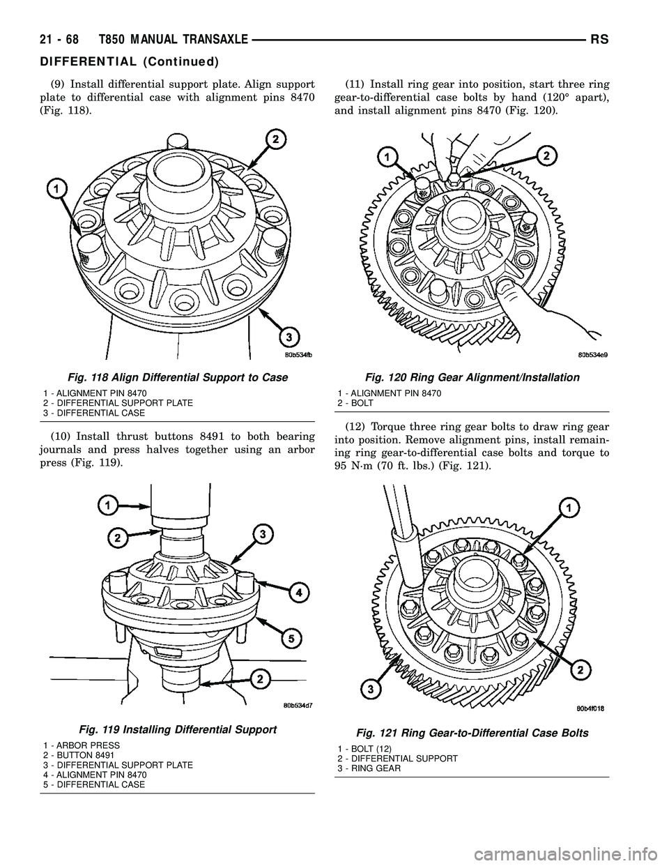
(9) Install differential support plate. Align support
plate to differential case with alignment pins 8470
(Fig. 118).
(10) Install thrust buttons 8491 to both bearing
journals and press halves together using an arbor
press (Fig. 119).(11) Install ring gear into position, start three ring
gear-to-differential case bolts by hand (120É apart),
and install alignment pins 8470 (Fig. 120).
(12) Torque three ring gear bolts to draw ring gear
into position. Remove alignment pins, install remain-
ing ring gear-to-differential case bolts and torque to
95 N´m (70 ft. lbs.) (Fig. 121).
Fig. 118 Align Differential Support to Case
1 - ALIGNMENT PIN 8470
2 - DIFFERENTIAL SUPPORT PLATE
3 - DIFFERENTIAL CASE
Fig. 119 Installing Differential Support
1 - ARBOR PRESS
2 - BUTTON 8491
3 - DIFFERENTIAL SUPPORT PLATE
4 - ALIGNMENT PIN 8470
5 - DIFFERENTIAL CASE
Fig. 120 Ring Gear Alignment/Installation
1 - ALIGNMENT PIN 8470
2 - BOLT
Fig. 121 Ring Gear-to-Differential Case Bolts
1 - BOLT (12)
2 - DIFFERENTIAL SUPPORT
3 - RING GEAR
21 - 68 T850 MANUAL TRANSAXLERS
DIFFERENTIAL (Continued)
Page 2401 of 2585

²FAN/MODE± The Fan and Mode knobs have
17 manual selectable positions. Manually changing
either of the rotary knobs for mode or fan speed set-
tings makes control of that blowe motor manual. If
only one is changed manually, the other remains
under automatic control. Pressing the HI-AUTO/LO-
AUTO rocker switch restores full automatic control.
²REAR CONTROL± When the Rear System
control knob is moved to the OFF position, there will
be a delay of approximately 1 second before the sys-
tem actually turns off. This delay is to prevent an
undesired blower dropout if the knob is moved
through OFF to the other selections.
²BLOWER DELAY TIMER± The word DELAY
is displayed at start-up to signify that the system is
waiting so that cold air will not be blowing. This tells
the operator that it is unnecessary to turn the sys-
tem off, raise the temperature setting or turn the fan
speed setting down to prevent cold air from blowing.
A countdown in minutes and seconds until the engine
is warm enough to begin delivering heat to the pas-
sengers alternates with the DELAY message at 25
second intervals. This countdown is based on actual
measurement of the rate of engine coolant tempera-
ture change. During the delay time, mix mode is
selected and the fan operates at a low speed to keep
the windshield fog free.
REAR CONTROL PANEL
Primary control of the rear compartment unit is in
the instrument panel center stack. The rear unit con-
trol knob there allows the driver to turn the rear
unit off, allow control by the intermediate seat occu-
pants by switching to the REAR position, or provide
fully automatic control based on the temperature set-
ting shown on the front control display.
²REAR CONTROL± Selecting automatic control
of the rear unit at the instrument panel, illuminates
a Locked Padlock in the rear control panel display.
Selecting REAR activates the rear control panel and
the Padlock then appears unlocked.
²FAN KNOB± The rear fan control has Off and
AUTO positions and a range of manual speed set-
tings that override the AUTO setting.
²MODE KNOB± The mode control allows inter-
mediate seat occupants to manually override the
automatic mode and select any balance of air flow
between overhead and floor outlets from full over-
head to full floor.
²SET TEMP± The rear set temp control will
operate identical to the front controls. If the front
control rear set temp button is pressed simulta-
neously with the rear control head, then the front
control head press events shall have priority, i.e. if
the front user presses Rear Set Temp down and therear user presses Set Temp up, then the rear set
temp will decrease.
DIAGNOSIS AND TESTING
DIAGNOSIS AND TESTING - A/C COOL DOWN
TEST
The heater-A/C control module can perform an A/C
cool down test, which is a test performed during the
manufacturing process to confirm that the air condi-
tioning system is performing satisfactorily. This test
can also provide a quick confirmation of air condi-
tioning system performance to the service technician.
If the test is completed satisfactorily, no further ser-
vice is required. If the test is failed, proceed to the
A/C Performance Test to confirm the A/C system is
operating properly, or use a DRBIIItscan tool to
diagnose the A/C system control and distribution sys-
tems. Refer to the appropriate diagnostic informa-
tion.
MANUAL TEMPERATURE CONTROL
The front blower speed and rear blower speed (if
equipped with rear HVAC) must be set to High and
the evaporator temperature sensor must be greater
than 13É C (55É F) or the test will fail immediately.
The test is activated by depressing the A/C and Rear
Wipe/Wash buttons simultaneously and holding them
depressed for no less than five seconds. The Rear
Wipe/Wash and A/C LEDs will blink on and off until
the test is complete. If the LEDs stop blinking before
two minutes, then the cool down test has been com-
pleted successfully. If the two minutes expire without
the expansion valve temperature reaching -6É C (20É
F) less than the outside air temperature, then the
cool down test has been failed and further A/C sys-
tem diagnosis is required. If the test is failed, the
LEDs will continue to blink until the vehicle has
been driven for greater than 1.6 km (8 miles).
AUTOMATIC TEMPERATURE CONTROL
The ambient air temperature in the room where
the vehicle will be tested must be a minimum of 21É
C (70ÉF) for this test. The test is activated by
depressing the A/C and PWR buttons simultaneously
and holding them depressed for no less than four sec-
onds. The snowflake icon and the DELAY text in the
ATC display will blink on and off alternately until
the test is complete. If the snowflake icon and the
DELAY text stop blinking before two minutes, then
the cool down test has been completed successfully. If
the two minutes expire without the evaporator tem-
perature reaching -6É C (20É F) less than the evapo-
rator initial temperature, then the cool down test has
been failed and further A/C system diagnosis is
24 - 6 HEATING & AIR CONDITIONINGRS
HEATING & AIR CONDITIONING (Continued)
Page 2415 of 2585

²The normally open terminal (87) provides a bat-
tery current output to the compressor clutch coil
through the compressor clutch relay output circuit
only when the compressor clutch relay coil is ener-
gized.
²The normally closed terminal (87A) is not con-
nected to any circuit in this application, but provides
a battery current output only when the compressor
clutch relay coil is de-energized.
The A/C compressor clutch relay cannot be
repaired and, if faulty or damaged, it must be
replaced. Refer to the appropriate wiring information
for diagnosis and testing of the micro-relay and for
complete HVAC wiring diagrams.
REMOVAL
(1) Disconnect and isolate the negative battery
cable.
(2) Remove the cover from the integrated power
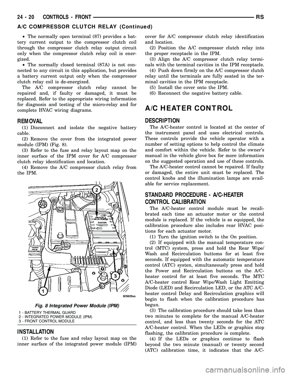
module (IPM) (Fig. 8).
(3) Refer to the fuse and relay layout map on the
inner surface of the IPM cover for A/C compressor
clutch relay identification and location.
(4) Remove the A/C compressor clutch relay from
the IPM.
INSTALLATION
(1) Refer to the fuse and relay layout map on the
inner surface of the integrated power module (IPM)cover for A/C compressor clutch relay identification
and location.
(2) Position the A/C compressor clutch relay into
the proper receptacle in the IPM.
(3) Align the A/C compressor clutch relay termi-
nals with the terminal cavities in the IPM receptacle.
(4) Push down firmly on the A/C compressor clutch
relay until the terminals are fully seated in the ter-
minal cavities in the IPM receptacle.
(5) Install the cover onto the IPM.
(6) Reconnect the negative battery cable.
A/C HEATER CONTROL
DESCRIPTION
The A/C-heater control is located at the center of
the instrument panel and uses electrical controls.
These controls provide the vehicle operator with a
number of setting options to help control the climate
and comfort within the vehicle. Refer to the owner's
manual in the vehicle glove box for more information
on the suggested operation and use of these controls.
The A/C-heater control cannot be repaired. If faulty
or damaged, the entire unit must be replaced. The
control knobs and the illumination lamps are avail-
able for service replacement.
STANDARD PROCEDURE - A/C-HEATER
CONTROL CALIBRATION
The A/C-heater control module must be recali-
brated each time an actuator motor or the control
module is replaced. If the vehicle is so equipped, the
calibration procedure also includes rear HVAC posi-
tions for each actuator motor.
(1) Turn the ignition switch to the On position.
(2) If equipped with the manual temperature con-
trol (MTC) system, press and hold the Rear Wipe/
Wash and Recirculation buttoms for at least five
seconds. If equipped with the automatic temperature
control (ATC) systen, simultaneously press and hold
the Power and Recirculation buttons on the A/C-
heater control for at least five seconds. The MTC
A/C-heater control Rear Wipe/Wash Light Emitting
Diode (LED) and Recirculation LED, or the ATC A/C-
heater control Delay and Recirculation graphics will
begin to flash when the calibration procedure has
begun.
(3) The calibration procedure should take less than
two minutes to complete for the manual A/C-heater
control, and less than twenty seconds for the ATC
A/C-heater control. When the LEDs or graphics stop
flashing, the calibration procedure is complete.
(4) If the LEDs or graphics continue to flash
beyond the two minute (manual) or twenty second
(ATC) calibration time, it indicates that the A/C-
Fig. 8 Integrated Power Module (IPM)
1 - BATTERY THERMAL GUARD
2 - INTEGRATED POWER MODULE (IPM)
3 - FRONT CONTROL MODULE
24 - 20 CONTROLS - FRONTRS
A/C COMPRESSOR CLUTCH RELAY (Continued)