2004 CHRYSLER VOYAGER ball joint
[x] Cancel search: ball jointPage 81 of 2585

ASSEMBLY - SHOCK ABSORBER (UPPER
BUSHING)
NOTE: This procedure applies to load-leveling
shock absorbers only.
(1) Install the Receiver, Special Tool 8526-1, into
the cup of the Ball Joint Press, Special Tool C-4212F,
and tighten the set screw. Install the Driver, Special
Tool 8526-2, on the tip of the Ball Joint Press screw
drive as shown (Fig. 24). Position the Driver this way
to seat the bushing to its correct depth.
(2) Place the shock absorber upper mounting eye
in the Receiver so the notch in the Receiver clears
the shock absorber body (Fig. 25).(3) Position the bushing between the shock
absorber eye and the Driver (Fig. 25). Tighten the
screw drive until the Driver, bushing, and shock
absorber eye are touching and squarely aligned.
(4) Press the bushing into the shock absorber eye
until the Driver bottoms against the face of the eye.
(5) Back off the Ball Joint Press screw drive and
remove the shock absorber from the press.
(6) Install the shock absorber on the vehicle. Refer
to REMOVAL AND INSTALLATION in this section
for the procedure.
INSTALLATION - SHOCK ABSORBER
(1) While holding shock absorber in position
against the frame rail, install the shock absorber
upper mounting bolt.
(2) Install the shock absorber lower mounting bolt
securing the lower end of the shock absorber to the
axle.
(3) Remove the support jack.
(4) Lower the vehicle to the ground so the full curb
weight of the vehicle is supported by the suspension.
(5) Tighten the upper and lower shock absorber
mounting bolt to a torque of 88 N´m (65 ft. lbs.).
SPRING - AWD
REMOVAL
(1) Raise vehicle on frame-contact hoist as follows:
(a) Position the hoist arm supporting the corner
of the vehicle to be serviced against a block of wood
placed on the body sill as shown (Fig. 26).
(b) Position the remaining hoist arms at each
corner of the vehicle in the normal fashion. (Refer
to LUBRICATION & MAINTENANCE/HOISTING
- STANDARD PROCEDURE)
(c) Raise the vehicle to a comfortable working
level.
(2) Position an under-hoist utility jack or transmis-
sion jack under rear axle toward the side needing
spring replacement. Jack pad should just contact
axle.
NOTE: If shock absorber bolt deflects upward dur-
ing removal, raise axle by adjusting support jack. If
shock absorber bolt deflects downward during
removal, lower axle by adjusting support jack (or by
pulling on axle).
(3) Begin removal of the shock absorber lower
mounting bolt (Fig. 27).
(4) Using 2 jack stands positioned under the outer
ends of the axle, raise the axle enough to remove the
weight of the axle from the rear springs.
(5) Loosen and remove the axle plate bolts from
the rear axle (Fig. 28).
Fig. 24 Special Tools Positioned For Installation
1 - SCREW DRIVE
Fig. 25 Installing Bushing In Shock Absorber
1 - BUSHING
2 - SCREW DRIVE
3 - SHOCK ABSORBER
4 - NOTCH
2 - 38 REAR SUSPENSIONRS
SHOCK ABSORBER (Continued)
Page 91 of 2585
For example, if the left camber is +0.3É and the right
camber is 0.0É, the cross camber would be +0.3É.
CASTER
Caster is the forward or rearward tilt of the steer-
ing knuckle in reference to the position of the upper
and lower ball joints. Caster is measured in degrees
of angle relative to a true vertical center line. This
line is viewed from the side of the tire and wheel
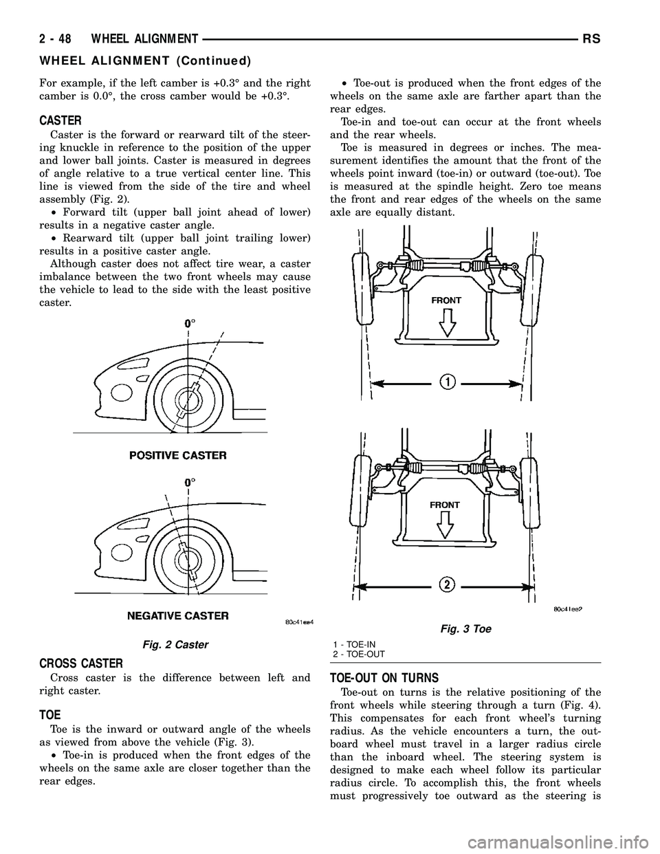
assembly (Fig. 2).
²Forward tilt (upper ball joint ahead of lower)
results in a negative caster angle.
²Rearward tilt (upper ball joint trailing lower)
results in a positive caster angle.
Although caster does not affect tire wear, a caster
imbalance between the two front wheels may cause
the vehicle to lead to the side with the least positive
caster.
CROSS CASTER
Cross caster is the difference between left and
right caster.
TOE
Toe is the inward or outward angle of the wheels
as viewed from above the vehicle (Fig. 3).
²Toe-in is produced when the front edges of the
wheels on the same axle are closer together than the
rear edges.²Toe-out is produced when the front edges of the
wheels on the same axle are farther apart than the
rear edges.
Toe-in and toe-out can occur at the front wheels
and the rear wheels.
Toe is measured in degrees or inches. The mea-
surement identifies the amount that the front of the
wheels point inward (toe-in) or outward (toe-out). Toe
is measured at the spindle height. Zero toe means
the front and rear edges of the wheels on the same
axle are equally distant.
TOE-OUT ON TURNS
Toe-out on turns is the relative positioning of the
front wheels while steering through a turn (Fig. 4).
This compensates for each front wheel's turning
radius. As the vehicle encounters a turn, the out-
board wheel must travel in a larger radius circle
than the inboard wheel. The steering system is
designed to make each wheel follow its particular
radius circle. To accomplish this, the front wheels
must progressively toe outward as the steering is
Fig. 2 Caster
Fig. 3 Toe
1 - TOE-IN
2 - TOE-OUT
2 - 48 WHEEL ALIGNMENTRS
WHEEL ALIGNMENT (Continued)
Page 92 of 2585
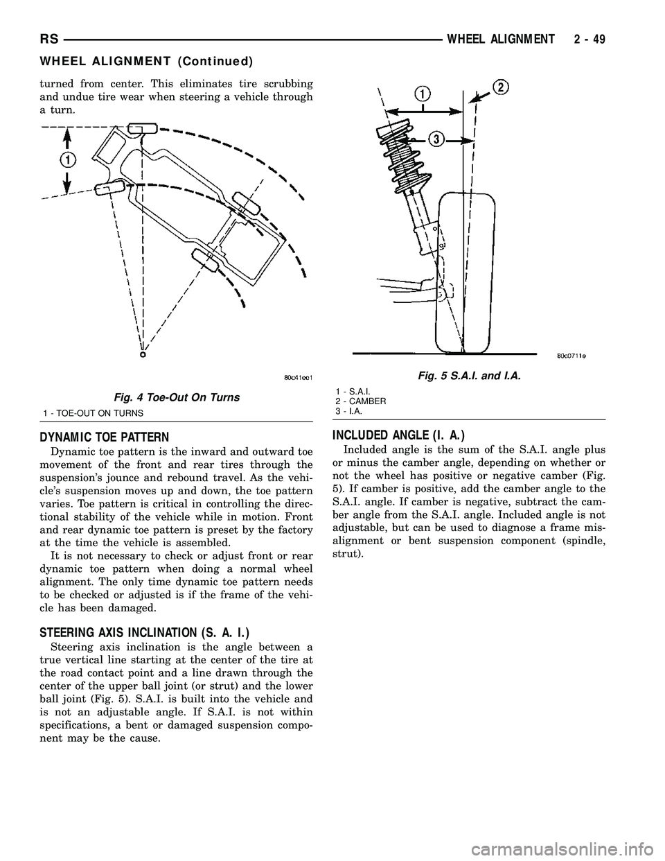
turned from center. This eliminates tire scrubbing
and undue tire wear when steering a vehicle through
a turn.
DYNAMIC TOE PATTERN
Dynamic toe pattern is the inward and outward toe
movement of the front and rear tires through the
suspension's jounce and rebound travel. As the vehi-
cle's suspension moves up and down, the toe pattern
varies. Toe pattern is critical in controlling the direc-
tional stability of the vehicle while in motion. Front
and rear dynamic toe pattern is preset by the factory
at the time the vehicle is assembled.
It is not necessary to check or adjust front or rear
dynamic toe pattern when doing a normal wheel
alignment. The only time dynamic toe pattern needs
to be checked or adjusted is if the frame of the vehi-
cle has been damaged.
STEERING AXIS INCLINATION (S. A. I.)
Steering axis inclination is the angle between a
true vertical line starting at the center of the tire at
the road contact point and a line drawn through the
center of the upper ball joint (or strut) and the lower
ball joint (Fig. 5). S.A.I. is built into the vehicle and
is not an adjustable angle. If S.A.I. is not within
specifications, a bent or damaged suspension compo-
nent may be the cause.
INCLUDED ANGLE (I. A.)
Included angle is the sum of the S.A.I. angle plus
or minus the camber angle, depending on whether or
not the wheel has positive or negative camber (Fig.
5). If camber is positive, add the camber angle to the
S.A.I. angle. If camber is negative, subtract the cam-
ber angle from the S.A.I. angle. Included angle is not
adjustable, but can be used to diagnose a frame mis-
alignment or bent suspension component (spindle,
strut).
Fig. 4 Toe-Out On Turns
1 - TOE-OUT ON TURNS
Fig. 5 S.A.I. and I.A.
1 - S.A.I.
2 - CAMBER
3 - I.A.
RSWHEEL ALIGNMENT2-49
WHEEL ALIGNMENT (Continued)
Page 93 of 2585

THRUST ANGLE
Thrust angle is the averaged direction the rear
wheels are pointing in relation to the vehicle's center
line (Fig. 6). The presence of negative or positive
thrust angle causes the rear tires to track improperly
to the left or right of the front tires (dog tracking).
²Negative thrust angle means the rear tires are
tracking to the left of the front tires.
²Positive thrust angle means the rear tires are
tracking to the right of the front tires.
Improper tracking can cause undue tire wear, a
lead or pull and a crooked steering wheel. Excessive
thrust angle can usually be corrected by adjusting
the rear wheel toe so that each wheel has one-half of
the total toe measurement.
DIAGNOSIS AND TESTING - SUSPENSION AND STEERING
CONDITION POSSIBLE CAUSES CORRECTION
Front End Whine On Turns 1. Defective wheel bearing 1. Replace wheel bearing
2. Incorrect wheel alignment 2. Check and reset wheel alignment
3. Worn tires 3. Replace tires
Front End Growl Or
Grinding On Turns1. Defective wheel bearing 1. Replace wheel bearing
2. Engine mount grounding 2. Check for motor mount hitting frame
rail and reposition engine as required
3. Worn or broken C/V joint 3. Replace C/V joint
4. Loose wheel lug nuts 4. Verify wheel lug nut torque
5. Incorrect wheel alignment 5. Check and reset wheel alignment
6. Worn tires 6. Replace tires
7. Front strut pin in upper strut mount 7. Replace the front strut upper mount
and bearing
Front End Clunk Or Snap
On Turns1. Loose lug nuts 1. Verify wheel lug nut torque
2. Worn or broken C/V joint 2. Replace C/V joint
3. Worn or loose tie rod 3. Tighten or replace tie rod end
4. Worn or loose ball joint 4. Tighten or replace ball joint
5. Worn/loose control arm bushing 5. Replace control arm bushing
6. Loose stabilizer bar. 6. Tighten stabilizer bar to specified
torque
7. Loose strut mount to body
attachment7. Tighten strut attachment to specified
torque
8. Loose crossmember bolts 8. Tighten crossmember bolts to
specified torque
Fig. 6 Thrust Angle
2 - 50 WHEEL ALIGNMENTRS
WHEEL ALIGNMENT (Continued)
Page 94 of 2585
CONDITION POSSIBLE CAUSES CORRECTION
Front End Whine With
Vehicle Going Straight At A
Constant Speed1. Defective wheel bearing 1. Replace wheel bearing
2. Incorrect wheel alignment 2. Check and reset wheel alignment
3. Worn tires 3. Replace tires
4. Worn or defective transaxle gears or
bearings4. Replace transaxle gears or bearings
Front End Growl Or
Grinding With Vehicle
Going Straight At A
Constant Speed1. Engine mount grounding 1. Reposition engine as required
2. Worn or broken C/V joint 2. Replace C/V joint
Front End Whine When
Accelerating Or
Decelerating1. Worn or defective transaxle gears or
bearings1. Replace transaxle gears or bearings
Front End Clunk When
Accelerating Or
Decelerating1. Worn or broken engine mount 1. Replace engine mount
2. Worn or defective transaxle gears or
bearings2. Replace transaxle gears or bearings
3. Loose lug nuts 3. Verify wheel lug nut torque
4. Worn or broken C/V joint 4. Replace C/V joint
5. Worn or loose ball joint 5. Tighten or replace ball joint
6. Worn or loose control arm bushing 6. Replace control arm bushing
7. Loose crossmember bolts 7. Tighten crossmember bolts to
specified torque
8. Worn tie rod end 8. Replace tie rod end
Road Wander 1. Incorrect tire pressure 1. Inflate tires to recommended pressure
2. Incorrect front or rear wheel toe 2. Check and reset wheel toe
3. Worn wheel bearings 3. Replace wheel bearing
4. Worn control arm bushings 4. Replace control arm bushing
5. Excessive friction in steering gear 5. Replace steering gear
6. Excessive friction in steering shaft
coupling6. Replace steering coupler
7. Excessive friction in strut upper
bearing7. Replace strut bearing
Lateral Pull 1. Unequal tire pressure 1. Inflate all tires to recommended
pressure
2. Radial tire lead 2. Perform lead correction procedure
3. Incorrect front wheel camber 3. Check and reset front wheel camber
4. Power steering gear imbalance 4. Replace power steering gear
5. Wheel braking 5. Correct braking condition causing
lateral pull
RSWHEEL ALIGNMENT2-51
WHEEL ALIGNMENT (Continued)
Page 95 of 2585

CONDITION POSSIBLE CAUSES CORRECTION
Excessive Steering Free
Play1. Incorrect Steering Gear Adjustment 1. Adjust Or Replace Steering Gear
2. Worn or loose tie rod ends 2. Replace or tighten tie rod ends
3. Loose steering gear mounting bolts 3. Tighten steering gear bolts to specified
torque
4. Loose or worn steering shaft coupler 4. Replace steering shaft coupler
Excessive Steering Effort 1. Low tire pressure 1. Inflate all tires to recommended
pressure
2. Lack of lubricant in steering gear 2. Replace steering gear
3. Low power steering fluid level 3. Fill power steering fluid reservoir to
correct level
4. Loose power steering pump drive
belt4. Correctly adjust power steering pump
drive belt
5. Lack of lubricant in ball joints 5. Lubricate or replace ball joints
6. Steering gear malfunction 6. Replace steering gear
7. Lack of lubricant in steering coupler 7. Replace steering coupler
STANDARD PROCEDURE
STANDARD PROCEDURE - WHEEL ALIGNMENT
PRE-WHEEL ALIGNMENT INSPECTION
Before any attempt is made to change or correct
the wheel alignment, the following inspection and
necessary corrections must be made to ensure proper
alignment.
(1) Verify that the fuel tank is full of fuel. If the
tank is not full, the reduction in weight will affect
the curb height of the vehicle and the alignment
angles.
(2) The passenger and luggage compartments of
the vehicle should be free of any load that is not fac-
tory equipment.
(3) Check the tires on the vehicle. All tires must be
the same size and in good condition with approxi-
mately the same amount of tread wear. Inflate all
the tires to the recommended air pressure.
(4) Check the front wheel and tire assemblies for
excessive radial runout.
(5) Inspect lower ball joints and all steering link-
age for looseness, binding, wear or damage. Repair as
necessary.
(6) Check suspension fasteners for proper torque
and retighten as necessary.
(7) Inspect all suspension component rubber bush-
ings for signs of wear or deterioration. Replace any
faulty bushings or components before aligning the
vehicle.
(8) Check the vehicle's curb height to verify it is
within specifications. Refer to Curb Height Measure-
ment.
WHEEL ALIGNMENT SETUP
(1) Position the vehicle on an alignment rack.
(2) Install all required alignment equipment on
the vehicle per the alignment equipment manufactur-
er's instructions. On this vehicle, a four-wheel align-
ment is recommended.
NOTE: Prior to reading the vehicle's alignment
readouts, the front and rear of vehicle should be
jounced. Induce jounce (rear first, then front) by
grasping the center of the bumper and jouncing
each end of vehicle an equal number of times. The
bumper should always be released when vehicle is
at the bottom of the jounce cycle.
(3) Read the vehicle's current front and rear align-
ment settings. Compare the vehicle's current align-
ment settings to the vehicle specifications for camber,
caster and toe-in. (Refer to 2 - SUSPENSION/
WHEEL ALIGNMENT - SPECIFICATIONS)
(4) If front camber and caster are not within spec-
ifications, proceed to CAMBER AND CASTER below.
If caster and camber are within specifications, pro-
ceed to TOE which can be found following CAMBER
AND CASTER. Rear camber, caster and toe are not
adjustable. If found not to be within specifications,
reinspect for damaged suspension or body compo-
nents and replace as necessary.
CAMBER AND CASTER
Camber and caster settings on this vehicle are
determined at the time the vehicle is designed, by
the location of the vehicle's suspension components.
This is referred to as NET BUILD. The result is no
2 - 52 WHEEL ALIGNMENTRS
WHEEL ALIGNMENT (Continued)
Page 1505 of 2585
REMOVAL
The front cradle crossmember must be installed in
the design location to achieve proper front end sus-
pension alignment. If the cradle crossmember is
removed without applying reference marks on the
frame rails, align the cradle crossmember according
to the dimensions provided in this group.
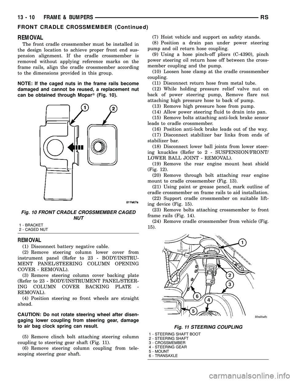
NOTE: If the caged nuts in the frame rails become
damaged and cannot be reused, a replacement nut
can be obtained through MoparT(Fig. 10).
REMOVAL
(1) Disconnect battery negative cable.
(2) Remove steering column lower cover from
instrument panel (Refer to 23 - BODY/INSTRU-
MENT PANEL/STEERING COLUMN OPENING
COVER - REMOVAL).
(3) Remove steering column cover backing plate
(Refer to 23 - BODY/INSTRUMENT PANEL/STEER-
ING COLUMN COVER BACKING PLATE -
REMOVAL).
(4) Position steering so front wheels are straight
ahead.
CAUTION: Do not rotate steering wheel after disen-
gaging lower coupling from steering gear, damage
to air bag clock spring can result.
(5) Remove clinch bolt attaching steering column
coupling to steering gear shaft (Fig. 11).
(6) Remove steering column coupling from tele-
scoping steering gear shaft.(7) Hoist vehicle and support on safety stands.
(8) Position a drain pan under power steering
pump and oil return hose coupling.
(9) Using a hose pinch-off pliers (C-4390), pinch
power steering oil return hose off between the cross-
member coupling and the pump.
(10) Loosen hose clamp at the cradle crossmember
coupling.
(11) Disconnect return hose from metal tube.
(12) While holding pressure relief valve nut on
back of power steering pump, Remove flare nut
attaching high pressure hose to back of pump.
(13) Remove high pressure hose from pump.
(14) Allow power steering fluid to drain into pan.
(15) Remove bolts attaching anti-lock brake sensor
leads to cradle crossmember.
(16) Position anti-lock brake leads out of the way.
(17) Disconnect stabilizer bar links from ends of
stabilizer bar.
(18) Disconnect lower ball joints from lower steer-
ing knuckles (Refer to 2 - SUSPENSION/FRONT/
LOWER BALL JOINT - REMOVAL).
(19) Remove the rear engine mount heat shield
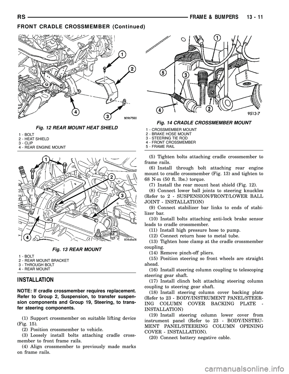
(Fig. 12).
(20) Remove through bolt attaching rear engine
mount to cradle crossmember (Fig. 13).
(21) Using paint or grease pencil, mark outline of
cradle crossmember on frame rails to aid installation.
(22) Support cradle crossmember on suitable lift-
ing device (Fig. 15).
(23) Remove bolts attaching crossmember to front
frame rails (Fig. 14).
(24) Remove cradle crossmember from vehicle (Fig.
15).
Fig. 10 FRONT CRADLE CROSSMEMBER CAGED
NUT
1 - BRACKET
2 - CAGED NUT
Fig. 11 STEERING COUPLING
1 - STEERING SHAFT BOOT
2 - STEERING SHAFT
3 - CROSSMEMBER
4 - STEERING GEAR
5 - MOUNT
6 - TRANSAXLE
13 - 10 FRAME & BUMPERSRS
FRONT CRADLE CROSSMEMBER (Continued)
Page 1506 of 2585
INSTALLATION
NOTE: If cradle crossmember requires replacement.
Refer to Group 2, Suspension, to transfer suspen-
sion components and Group 19, Steering, to trans-
fer steering components.
(1) Support crossmember on suitable lifting device
(Fig. 15).
(2) Position crossmember to vehicle.
(3) Loosely install bolts attaching cradle cross-
member to front frame rails.
(4) Align crossmember to previously made marks
on frame rails.(5) Tighten bolts attaching cradle crossmember to
frame rails.
(6) Install through bolt attaching rear engine
mount to cradle crossmember (Fig. 13) and tighten to
68 N´m (50 ft. lbs.) torque.
(7) Install the rear mount heat shield (Fig. 12).
(8) Connect lower ball joints to steering knuckles
(Refer to 2 - SUSPENSION/FRONT/LOWER BALL
JOINT - INSTALLATION)
(9) Connect stabilizer bar links to ends of stabi-
lizer bar.
(10) Install bolts attaching anti-lock brake sensor
leads to cradle crossmember.
(11) Install high pressure hose to pump.
(12) Connect return hose to metal tube.
(13) Tighten hose clamp at the cradle crossmember
coupling.
(14) Remove pinch-off pliers.
(15) Position steering so front wheels are straight
ahead.
(16) Install steering column coupling to telescoping
steering gear shaft.
(17) Install clinch bolt attaching steering column
coupling to steering gear shaft.
(18) Install steering column cover backing plate
(Refer to 23 - BODY/INSTRUMENT PANEL/STEER-
ING COLUMN COVER BACKING PLATE -
INSTALLATION)
(19) Install steering column lower cover from
instrument panel (Refer to 23 - BODY/INSTRU-
MENT PANEL/STEERING COLUMN OPENING
COVER - INSTALLATION).
(20) Connect battery negative cable.
Fig. 12 REAR MOUNT HEAT SHIELD
1 - BOLT
2 - HEAT SHIELD
3 - CLIP
4 - REAR ENGINE MOUNT
Fig. 13 REAR MOUNT
1 - BOLT
2 - REAR MOUNT BRACKET
3 - THROUGH BOLT
4 - REAR MOUNT
Fig. 14 CRADLE CROSSMEMBER MOUNT
1 - CROSSMEMBER MOUNT
2 - BRAKE HOSE MOUNT
3 - STEERING TIE ROD
4 - FRONT CROSSMEMBER
5 - FRAME RAIL
RSFRAME & BUMPERS13-11
FRONT CRADLE CROSSMEMBER (Continued)