2004 CHRYSLER VOYAGER run flat
[x] Cancel search: run flatPage 658 of 2585

(2) Turn the ignition key to the ON position. Exit
vehicle with the scan tool.
(3) After checking that no one is inside the vehicle,
connect the battery negative remote terminal.
(4) Read and record theACTIVEDiagnostic Trou-
ble Code (DTC) data.
(5) Read and record anySTOREDDTC's.
(6) Refer to the proper Body Diagnostic Procedures
manual if any DTC's are found in Step 4 and Step 5.
(7) If the airbag warning lamp either fails to light,
or goes ON and stays ON, there is a system malfunc-
tion. To test the airbag warning lamp (bulb) opera-
tion in the cluster, refer to Electrical, Instrument
Cluster, Diagnosis and Testing - Instrument Cluster.
Refer to the proper Body Diagnostic Procedures man-
ual for any other system problems.
STANDARD PROCEDURE
STANDARD PROCEDURE - HANDLING
AIRBAGS
DEPLOYED AIRBAG
The vehicle interior may contain a very small
amount of sodium hydroxide powder, a by-product of
airbag deployment. Sodium hydroxide powder can
irritate the skin, eyes, nose and throat. Wear safety
glasses, rubber gloves, and long sleeved clothing
when cleaning any of the powder residue from the
vehicle.
If you find that the cleanup is irritating your skin,
run cool water over the affected area. Also, if you
experience nasal or throat irritation, exit the vehicle
for fresh air until the irritation ceases. If irritation
continues, see a physician.
UNDEPLOYED AIRBAG
The airbags must be stored in its original special
container until used for service. At no time should a
source of electricity be permitted near the inflator on
the back of an airbag module. When carrying or han-
dling an undeployed airbag module, the trim side of
the airbag should be pointing away from the body to
minimize possibility of injury if accidental deploy-
ment occurs. Do not place undeployed airbag face
down on a solid surface, the airbag will propel into
the air if accidental deployment occurs.
STANDARD PROCEDURE - SERVICE AFTER AN
AIRBAG DEPLOYMENT
DRIVER AIRBAG
After a Driver Airbag has been deployed due to a
collision, the followingMUSTbe replaced:
²Driver Airbag²Clock Spring Assembly
²Steering Wheel
²Complete Steering Column Assembly w/Lower
Steering Column Coupler
All other airbag and vehicle components should be
closely inspected following any airbag deployment,
and should be replaced when visible damage is
incurred.
PASSENGER AIRBAG
After a Passenger Airbag has been deployed due to
a collision. the followingMUSTbe replaced:
²Passenger Airbag
²Instrument Panel and Pad Assembly
All other airbag and vehicle components should be
closely inspected following any airbag deployment,
and should be replaced when visible damage is
incurred.
SEAT AIRBAG
After a Seat Airbag has been deployed due to a col-
lision. the followingMUSTbe replaced:
²Complete Seat Back Assembly
All other airbag and vehicle components should be
closely inspected following any airbag deployment,
and should be replaced when visible damage is
incurred.
SEAT BELTS AND TENSIONERS
After a frontal impact where an airbag has been
deployed due to a collision. the followingMUSTbe
replaced:
²Front Seat Belt Buckle (driver and passenger)
with integral Tensioners.
All other seat belts should be closely inspected for
cuts, tears, fraying, or damage in any way following
any frontal impact or airbag deployment. The other
seat belts are to be replaced when visible damage is
incurred. Inspect the Lower Anchors and Tether for
CHildren (LATCH) child restraint anchors for dam-
age after an impact event and replace as needed.
CLEAN UP PROCEDURE
Roll or fold the airbag towards its mounting point
(i.e. instrument panel, steering wheel, or seat back).
Then tape the ripped cover over the deployed airbag
if applicable.
Use a vacuum cleaner to remove any residual pow-
der from the vehicle interior. Work from the outside
in to avoid kneeling or sitting in a contaminated
area. Vacuum the heater and A/C outlets as well (Fig.
1). If the heater or air conditioner was in RECIRC
mode at time of airbag deployment, operate blower
motor on low speed and vacuum powder residue
expelled from the heater and A/C outlets. Multiple
RSRESTRAINTS8O-3
RESTRAINTS (Continued)
Page 682 of 2585

DIAGNOSIS AND TESTING
DIAGNOSIS AND TESTING - SENTRY KEY
REMOTE ENTRY SYSTEM
WARNING: ON VEHICLES EQUIPPED WITH AIR-
BAGS, REFER TO ELECTRICAL, RESTRAINTS,
WARNINGS, BEFORE ATTEMPTING COMPONENT
DIAGNOSIS OR SERVICE. FAILURE TO TAKE THE
PROPER PRECAUTIONS COULD RESULT IN ACCI-
DENTAL AIRBAG DEPLOYMENT AND POSSIBLE
PERSONAL INJURY OR DEATH.
NOTE: The following tests may not prove conclu-
sive in the diagnosis of this system. The most reli-
able, efficient, and accurate means to diagnose the
Sentry Key Remote Entry System (SKREES)
involves the use of a DRBIIITscan tool. Refer to the
proper Body Diagnostic Procedures information.
The Sentry Key Remote Entry System (SKREES)
and the Programmable Communication Interface
(PCI) bus network should be diagnosed using a
DRBIIItscan tool. The DRBIIItwill allow confirma-
tion that the PCI bus is functional, that the Sentry
Key Remote Entry Module (SKREEM) is placing the
proper messages on the PCI bus, and that the Pow-
ertrain Control Module (PCM) is receiving the PCI
bus messages. Refer to the proper Body Diagnostic
Procedures information, and Wiring Diagrams for
complete circuit descriptions and diagrams.
(1) Check the fuses in the Integrated Power Mod-
ule (IPM). If OK, go to Step 2. If not OK, repair the
shorted circuit or component as required and replace
the faulty fuse.
(2) Disconnect and isolate the battery negative
remote cable from the remote terminal. Unplug the
wire harness connector at the SKREEM. Check for
continuity between the ground circuit cavity of the
SKREEM wire harness connector and a good ground.
There should be continuity. If OK, go to Step 3. If not
OK, repair the open circuit to ground as required.
(3) Connect the battery negative cable. Check for
battery voltage at the fused B(+) circuit cavity of the
SKREEM wire harness connector. If OK, go to Step
4. If not OK, repair the open circuit to the fuse in the
IPM as required.
(4) Turn the ignition switch to the ON position.
Check for battery voltage at the fused ignition switch
output (run/start) circuit cavity of the SKREEM wire
harness connector. If OK, use a DRBIIItscan tool
and the proper Body Diagnostic Procedures informa-
tion to complete the diagnosis of the SKREES. If not
OK, repair the open circuit to the fuse in the IPM as
required.
DIAGNOSIS AND TESTING - VEHICLE THEFT
SECURITY SYSTEM
Refer to the appropriate wiring information. The
wiring information includes wiring diagrams, proper
wire and connector repair procedures, further details
on wire harness routing and retention, as well as
pin-out and location views for the various wire har-
ness connectors, splices and grounds. Using a
DRBIIItscan tool. Refer to the proper Body Diagnos-
tic Procedures information for test procedures.
HOOD AJAR SWITCH -
EXPORT
REMOVAL
(1) Disconnect and isolate the battery negative
cable.
(2) Using a small flat blade screwdriver, pry trig-
ger switch from the bracket on the left fender well.
(3) Disconnect the hood ajar switch from the wire
connector and remove from vehicle.
INSTALLATION
(1) Connect the hood ajar switch to the wire conec-
tor.
(2) Press the hood ajar switch into position on the
bracket located on the left inner fender well.
(3) Reconnect the battery negative cable.
(4) Close the hood and check for proper operation.
SENTRY KEY REMOTE ENTRY
MODULE
DESCRIPTION
The Sentry Key Remote Entry Module (SKREEM)
performs the functions of the Sentry Key Immobilizer
Module (SKIM), Remote Keyless Entry (RKE) Mod-
ule, and the Tire Pressure Monitoring (TPM) System
(previously part of the Electronic Vehicle Information
Center (EVIC).
The SKREEM is located in the same location as
the SKIM was and is mounted the same way. It looks
identical, but has added capabilities.
SENTRY KEY IMMOBILIZER
The Sentry Key Immobilizer System (SKIS)
authenticates an electronically coded Transponder
Key placed into the ignition and sends a valid/invalid
key message to the Powertrain Control Module
(PCM) based upon the results. The ªVALID/INVALID
KEYº message communication is performed using a
rolling code algorithm via the Programmable Com-
munication Interface (PCI) data bus. A ªVALID KEYº
RSVEHICLE THEFT SECURITY8Q-3
VEHICLE THEFT SECURITY (Continued)
Page 695 of 2585

FRONT WASHER PUMP
MOTOR
REMOVAL
(1) Disconnect and isolate the battery negative
cable.
(2) Remove the engine fresh air housing inside the
engine compartment (Refer to 9 - ENGINE/AIR
INTAKE SYSTEM/AIR CLEANER HOUSING -
REMOVAL).
(3) Disconnect the washer hose at the in-line con-
nector forward of the cowl grille so that the in-line
connector remains with the washer hose from the
fresh air plenum.
(4) Disconnect the washer hose from the hose clip
located on the front fender side shield.
(5) Remove the filler tube screw.
(6) Hoist and support vehicle on hoist or jack
stands.
(7) Remove the right front wheel and tire assembly
(Refer to 22 - TIRES/WHEELS - REMOVAL).
(8) Disconnect the left right front wheelhouse
splash shield and move aside (Refer to 23 - BODY/
EXTERIOR/WHEELHOUSE SPLASH SHIELD -
REMOVAL).
(9) Drain washer fluid from the reservoir and into
a suitable clean container. This can be done by dis-
connecting the windshield washer hose from the
front (outboard) washer pump and allowing the
washer fluid to drain into a container through a tem-
porary jumper hose connected to the front washer
pump.
(10) Disconnect the electrical body harness connec-
tors to the washer pump motors and the fluid level
sensor. Slide the red lock on the connector to the
release position, then, depress the black tab and pull
the connector off the pump or sensor.
(11) Remove the two reservoir mounting screws.
(12) Disconnect the reservoir from the body mount
by raising the reservoir upward slightly and then
down so that the reservoir filler neck and front
washer hose pull through the opening in the front
fender side shield.
(13) Remove pump from reservoir by pulling pump
upper retention tab away from reservoir cavity and
then lifting pump up from mounting grommet. Do
not damage reservoir/pump sealing surface or punc-
ture reservoir during removal.
(14) Remove pump grommet and discard.
INSTALLATION
(1) Use new grommet when installing a new pump
assembly.
(2) Assure pump upper retention tab is pressed
into reservoir slot and that pump is rotated flatagainst the reservoir and that pump connector is fac-
ing up in the fully seated position. Assure the pump
is aligned to and fully seated in the reservoir cavity.
(3) Push filler neck and front washer hose through
the opening in the front fender side shield. Connect
the reservoir to the body mount by lowering the res-
ervoir down.
(4) Install the two reservoir mounting screws.
Torque screws to 8.5 - 11.3 N´m (75 - 100 in. lbs.).
(5) Connect the electrical body harness connectors
to the washer pump motors and the fluid level sen-
sor. Slide the red lock on the connector to the closed
or locked position.
(6) Assure that washer hose is properly routed to
prevent pinching and possible inoperative washers.
(7) Connect the left right front wheelhouse splash
shield and move aside (Refer to 23 - BODY/EXTERI-
OR/WHEELHOUSE SPLASH SHIELD - INSTALLA-
TION).
(8) Install the right front wheel and tire assembly
(Refer to 22 - TIRES/WHEELS - INSTALLATION).
(9) lower vehicle from hoist or jack stands.
(10) Install the filler tube screw. Torque screw to
8.5 - 11.3 N´m (75 - 100 in. lbs.).
(11) Connect the washer hose to the hose clip
located on the front fender side shield.
(12) Connect the washer hose at the in-line con-
nector forward of the cowl grille.
(13) Install the engine fresh air housing inside the
engine compartment (Refer to 9 - ENGINE/AIR
INTAKE SYSTEM/AIR CLEANER HOUSING -
INSTALLATION).
(14) Connect the battery negative cable.
(15) Verify system operation.
FRONT WIPER ARMS
STANDARD PROCEDURE - FRONT WIPER ARM
ALIGNMENT
(1) Verify wiper blade element condition and wiper
arm spring tension. Run wipers in low speed mode
while applying water to the windshield. Observe the
wiper blade that is chattering or skipping across the
windshield. If the wiper element is not rolling over
when the wiper direction reverses, align the wiper
arm. The extension bar portion of the wiper arm
must be twisted in the proper direction to allow the
wiper element to roll over when the direction
reverses.
(2) Place two small adjustable wrenches placed 50
mm (2 in.) apart on the wiper arm extension rod.
(3) Twist the extension rod slightly in the opposite
direction that the element is laying on the wind-
shield while holding the wrench closest to the pivot
stationary.
8R - 8 WIPERS/WASHERSRS
Page 1316 of 2585

DESCRIPTION SPECIFICATION
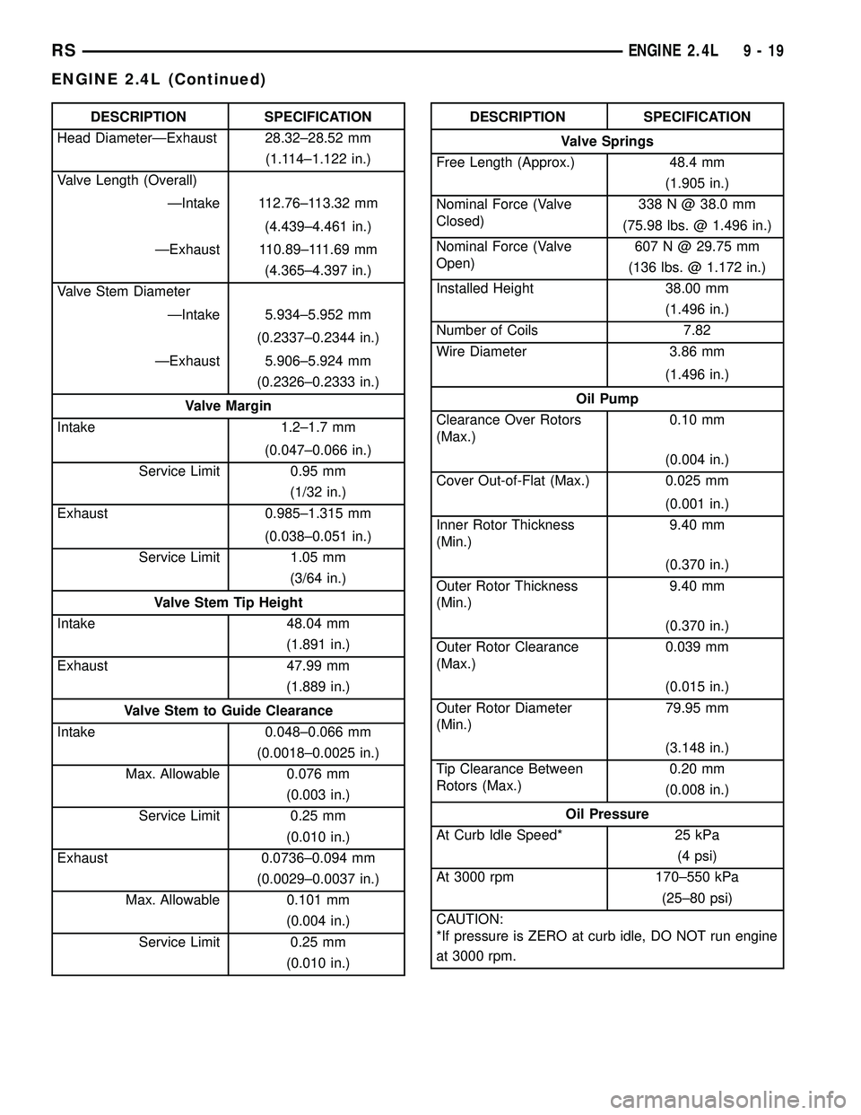
Head DiameterÐExhaust 28.32±28.52 mm
(1.114±1.122 in.)
Valve Length (Overall)
ÐIntake 112.76±113.32 mm
(4.439±4.461 in.)
ÐExhaust 110.89±111.69 mm
(4.365±4.397 in.)
Valve Stem Diameter
ÐIntake 5.934±5.952 mm
(0.2337±0.2344 in.)
ÐExhaust 5.906±5.924 mm
(0.2326±0.2333 in.)
Valve Margin
Intake 1.2±1.7 mm
(0.047±0.066 in.)
Service Limit 0.95 mm
(1/32 in.)
Exhaust 0.985±1.315 mm
(0.038±0.051 in.)
Service Limit 1.05 mm
(3/64 in.)
Valve Stem Tip Height
Intake 48.04 mm
(1.891 in.)
Exhaust 47.99 mm
(1.889 in.)
Valve Stem to Guide Clearance
Intake 0.048±0.066 mm
(0.0018±0.0025 in.)
Max. Allowable 0.076 mm
(0.003 in.)
Service Limit 0.25 mm
(0.010 in.)
Exhaust 0.0736±0.094 mm
(0.0029±0.0037 in.)
Max. Allowable 0.101 mm
(0.004 in.)
Service Limit 0.25 mm
(0.010 in.)DESCRIPTION SPECIFICATION
Valve Springs
Free Length (Approx.) 48.4 mm
(1.905 in.)
Nominal Force (Valve
Closed)338 N @ 38.0 mm
(75.98 lbs. @ 1.496 in.)
Nominal Force (Valve
Open)607 N @ 29.75 mm
(136 lbs. @ 1.172 in.)
Installed Height 38.00 mm
(1.496 in.)
Number of Coils 7.82
Wire Diameter 3.86 mm
(1.496 in.)
Oil Pump
Clearance Over Rotors
(Max.)0.10 mm
(0.004 in.)
Cover Out-of-Flat (Max.) 0.025 mm
(0.001 in.)
Inner Rotor Thickness
(Min.)9.40 mm
(0.370 in.)
Outer Rotor Thickness
(Min.)9.40 mm
(0.370 in.)
Outer Rotor Clearance
(Max.)0.039 mm
(0.015 in.)
Outer Rotor Diameter
(Min.)79.95 mm
(3.148 in.)
Tip Clearance Between
Rotors (Max.)0.20 mm
(0.008 in.)
Oil Pressure
At Curb Idle Speed* 25 kPa
(4 psi)
At 3000 rpm 170±550 kPa
(25±80 psi)
CAUTION:
*If pressure is ZERO at curb idle, DO NOT run engine
at 3000 rpm.
RSENGINE 2.4L9-19
ENGINE 2.4L (Continued)
Page 1350 of 2585

OIL
STANDARD PROCEDURE
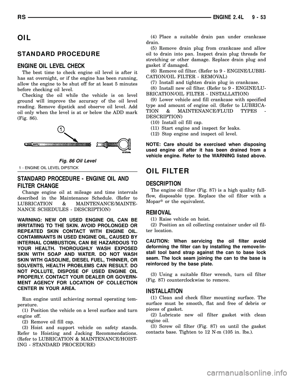
ENGINE OIL LEVEL CHECK
The best time to check engine oil level is after it
has sat overnight, or if the engine has been running,
allow the engine to be shut off for at least 5 minutes
before checking oil level.
Checking the oil while the vehicle is on level
ground will improve the accuracy of the oil level
reading. Remove dipstick and observe oil level. Add
oil only when the level is at or below the ADD mark
(Fig. 86).
STANDARD PROCEDURE - ENGINE OIL AND
FILTER CHANGE
Change engine oil at mileage and time intervals
described in the Maintenance Schedule. (Refer to
LUBRICATION & MAINTENANCE/MAINTE-
NANCE SCHEDULES - DESCRIPTION)
WARNING: NEW OR USED ENGINE OIL CAN BE
IRRITATING TO THE SKIN. AVOID PROLONGED OR
REPEATED SKIN CONTACT WITH ENGINE OIL.
CONTAMINANTS IN USED ENGINE OIL, CAUSED BY
INTERNAL COMBUSTION, CAN BE HAZARDOUS TO
YOUR HEALTH. THOROUGHLY WASH EXPOSED
SKIN WITH SOAP AND WATER. DO NOT WASH
SKIN WITH GASOLINE, DIESEL FUEL, THINNER, OR
SOLVENTS, HEALTH PROBLEMS CAN RESULT. DO
NOT POLLUTE, DISPOSE OF USED ENGINE OIL
PROPERLY. CONTACT YOUR DEALER OR GOVERN-
MENT AGENCY FOR LOCATION OF COLLECTION
CENTER IN YOUR AREA.
Run engine until achieving normal operating tem-
perature.
(1) Position the vehicle on a level surface and turn
engine off.
(2) Remove oil fill cap.
(3) Hoist and support vehicle on safety stands.
Refer to Hoisting and Jacking Recommendations.
(Refer to LUBRICATION & MAINTENANCE/HOIST-
ING - STANDARD PROCEDURE)(4) Place a suitable drain pan under crankcase
drain.
(5) Remove drain plug from crankcase and allow
oil to drain into pan. Inspect drain plug threads for
stretching or other damage. Replace drain plug and
gasket if damaged.
(6) Remove oil filter. (Refer to 9 - ENGINE/LUBRI-
CATION/OIL FILTER - REMOVAL)
(7) Install and tighten drain plug in crankcase.
(8) Install new oil filter. (Refer to 9 - ENGINE/LU-
BRICATION/OIL FILTER - INSTALLATION)
(9) Lower vehicle and fill crankcase with specified
type and amount of engine oil. (Refer to LUBRICA-
TION & MAINTENANCE/FLUID TYPES -
DESCRIPTION)
(10) Install oil fill cap.
(11) Start engine and inspect for leaks.
(12) Stop engine and inspect oil level.
NOTE: Care should be exercised when disposing
used engine oil after it has been drained from a
vehicle engine. Refer to the WARNING listed above.
OIL FILTER
DESCRIPTION
The engine oil filter (Fig. 87) is a high quality full-
flow, disposable type. Replace the oil filter with a
Mopartor the equivalent.
REMOVAL
(1) Raise vehicle on hoist.
(2) Position an oil collecting container under oil fil-
ter location.
CAUTION: When servicing the oil filter avoid
deforming the filter can by installing the remove/in-
stall tool band strap against the can to base lock
seam. The lock seam joining the can to the base is
reinforced by the base plate.
(3) Using a suitable filter wrench, turn oil filter
(Fig. 87) counterclockwise to remove.
INSTALLATION
(1) Clean and check filter mounting surface. The
surface must be smooth, flat and free of debris or
pieces of gasket.
(2) Lubricate new oil filter gasket with clean
engine oil.
(3) Screw oil filter (Fig. 87) on until the gasket
contacts base. Tighten to 12 N´m (105 in. lbs.).
Fig. 86 Oil Level
1 - ENGINE OIL LEVEL DIPSTICK
RSENGINE 2.4L9-53
Page 1356 of 2585

(9) Disconnect throttle and speed control (if
equipped) cables from throttle lever and bracket.
(Refer to 14 - FUEL SYSTEM/FUEL INJECTION/
THROTTLE CONTROL CABLE - REMOVAL)
(10) Remove the EGR tube. (Refer to 25 - EMIS-
SIONS CONTROL/EXHAUST GAS RECIRCULA-
TION/TUBE - REMOVAL)
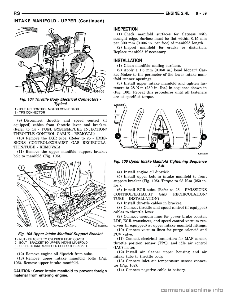
(11) Remove the upper manifold support bracket
bolt to manifold (Fig. 105).
(12) Remove engine oil dipstick from tube.
(13) Remove upper intake manifold bolts (Fig.
106). Remove upper intake manifold.
CAUTION: Cover intake manifold to prevent foreign
material from entering engine.
INSPECTION
(1) Check manifold surfaces for flatness with
straight edge. Surface must be flat within 0.15 mm
per 300 mm (0.006 in. per foot) of manifold length.
(2) Inspect manifold for cracks or distortion.
Replace manifold if necessary.
INSTALLATION
(1) Clean manifold sealing surfaces.
(2) Apply a 1.5 mm (0.060 in.) bead MopartGas-
ket Maker to the perimeter of the lower intake man-
ifold runner openings.
(3) Install upper intake manifold and tighten fas-
teners to 28 N´m (250 in. lbs.) in sequence shown in
(Fig. 106). Repeat this procedures until all fasteners
are at specified torque.
(4) Install engine oil dipstick.
(5) Install upper bolt in intake manifold to front
support bracket (Fig. 105). Torque to 28 N´m (250 in.
lbs.).
(6) Install EGR tube. (Refer to 25 - EMISSIONS
CONTROL/EXHAUST GAS RECIRCULATION/
TUBE - INSTALLATION)
(7) Install throttle cables in bracket.
(8) Connect throttle and speed control (if equipped)
cables to throttle lever.
(9) Connect vacuum lines for power brake booster,
LDP, EGR transducer, and speed control vacuum res-
ervoir (if equipped) at upper intake manifold fittings.
(10) Connect vacuum lines for purge solenoid and
PCV valve.
(11) Connect electrical connectors for MAP sensor,
throttle position sensor (TPS), and idle air control
(IAC) motor.
(12) Install air cleaner upper housing and air
intake tube to throttle body.
(13) Connect inlet air temperature sensor connec-
tor (Fig. 102).
(14) Connect negative cable to battery.
Fig. 104 Throttle Body Electrical Connectors -
Typical
1 - IDLE AIR CONTROL MOTOR CONNECTOR
2 - TPS CONNECTOR
Fig. 105 Upper Intake Manifold Support Bracket
1 - NUT - BRACKET TO CYLINDER HEAD COVER
2 - BOLT - BRACKET TO UPPER INTAKE MANIFOLD
3 - UPPER INTAKE MANIFOLD SUPPORT BRACKET
Fig. 106 Upper Intake Manifold Tightening Sequence
- 2.4L
RSENGINE 2.4L9-59
INTAKE MANIFOLD - UPPER (Continued)
Page 1388 of 2585

(47) Connect the radiator upper hose.
(48) Connect the heater hoses. Remove pinch-off
pliers from the rear heater hoses (if equipped).
(49) Install the radiator upper support crossmem-
ber (Refer to 23 - BODY/EXTERIOR/GRILLE OPEN-
ING REINFORCEMENT - INSTALLATION).
(50) Install the wiper module (Refer to 8 - ELEC-
TRICAL/WIPERS/WASHERS/WIPER MODULE -
INSTALLATION).
(51) Connect the fuel line to fuel rail (Refer to 14 -
FUEL SYSTEM/FUEL DELIVERY/FUEL LINES -
STANDARD PROCEDURE).
(52) Install the air cleaner and hoses.
(53) Install new oil filter. Fill engine crankcase
with proper oil to correct level.
(54) Connect negative cable to battery.
(55) Fill the cooling system (Refer to 7 - COOLING
- STANDARD PROCEDURE).
(56) Start engine and run until operating temper-
ature is reached.
(57) Adjust transmission linkage, if necessary.
SPECIFICATIONS
3.3/3.8L ENGINE
DESCRIPTION SPECIFICATION
General Specification
Type 60É V-6 Engine
Number of Cylinders 6
Displacement
Ð3.3L 3.3 Liters
(201 cu. in.)
Ð3.8L 3.8 Liters
(231 cu. in.)
Bore
Ð3.3L 93.0 mm
(3.66 in.)
Ð3.8L 96.0 mm
(3.779 in.)
Stroke
Ð3.3L 81.0 mm
(3.188 in.)
Ð3.8L 87.0 mm
(3.425 in.)
Compression Ratio
Ð3.3L 9.35:1
Ð3.8L 9.6:1
DESCRIPTION SPECIFICATION
Firing Order 1-2-3-4-5-6
Cylinder Number (Front
to Rear)
ÐFront Bank 2,4,6
ÐRear Bank 1,3,5
Compression PressureÐ
Minimum689.5 kPa
(100 psi)
Max. Variation Between
Cylinders25%
Cylinder Block
Cylinder Bore Diameter
(Standard)
Ð3.3L 92.993±93.007 mm
(3.661±3.6617 in.)
Ð3.8L 95.993±96.007 mm
(3.7792±3.780 in.)
Out-of-Round (Service
Limits)0.076 mm
(0.003 in.)
Taper (Service Limits) 0.051 mm
(0.002 in.)
Lifter Bore Diameter 22.980±23.010 mm
(0.905±0.906 in.)
Deck Surface Flatness
(Max.)0.1 mm
(0.004 in.)
Pistons
Piston Diameter
Ð3.3L ÐMeasured 39.8
mm (1.567 in.) from
piston top92.968±92.998 mm
(3.660±3.661 in.)
Ð3.8L ÐMeasured 33.01
mm (1.30 in.) from piston
top95.968±95.998 mm
(3.778±3.779 in.)
Clearance in Bore @
Size Location (New)-0.005±0.039 mm
(-0.0002±0.0015 in.)
Weight
Ð3.3L 362 5 grams
(12.77 0.1764 oz.)
Ð3.8L 426 5 grams
(15.03 0.1764 oz.)
Piston Pins
Type Press Fit in Rod
(Serviced as an
Assembly)
RSENGINE 3.3/3.8L9-91
ENGINE 3.3/3.8L (Continued)
Page 1391 of 2585

DESCRIPTION SPECIFICATION
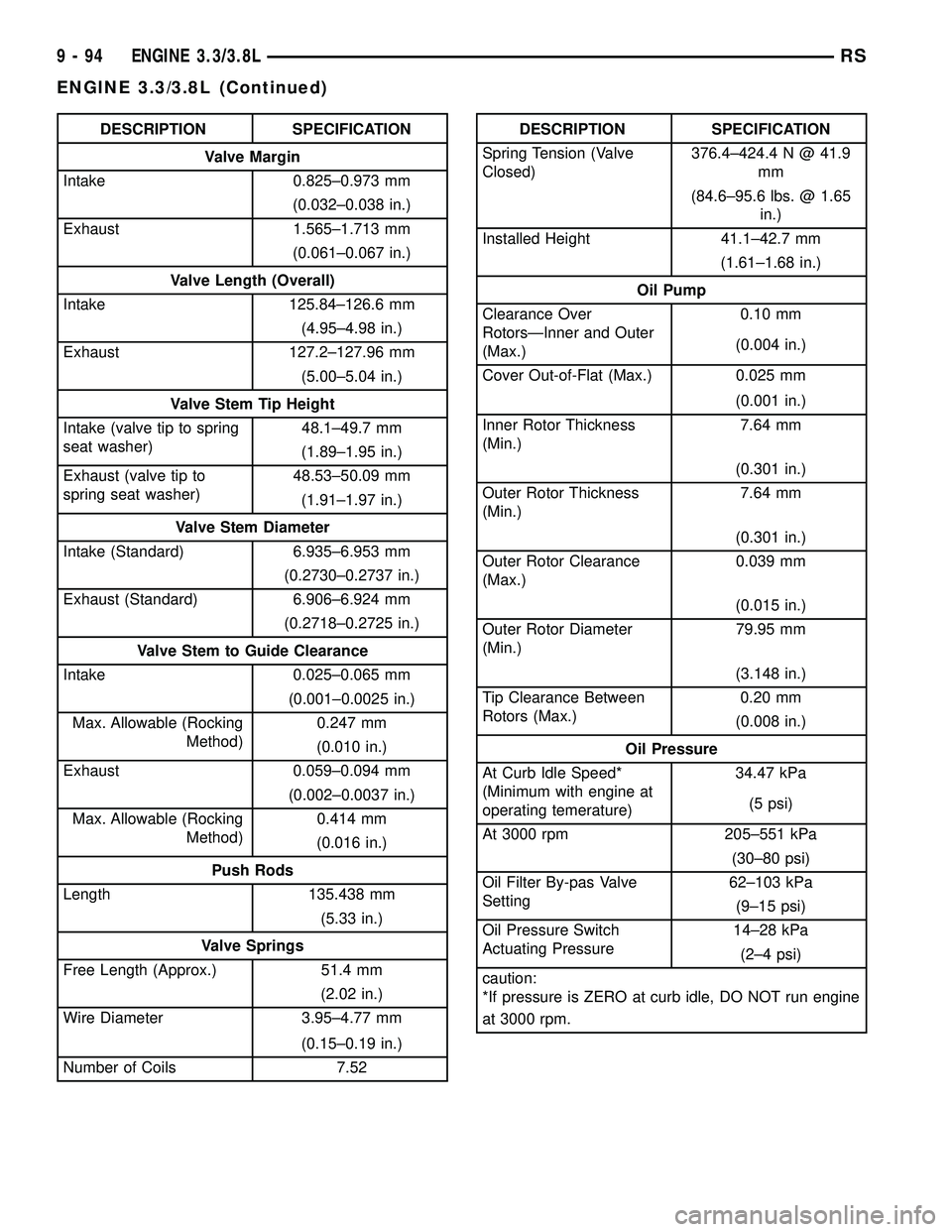
Valve Margin
Intake 0.825±0.973 mm
(0.032±0.038 in.)
Exhaust 1.565±1.713 mm
(0.061±0.067 in.)
Valve Length (Overall)
Intake 125.84±126.6 mm
(4.95±4.98 in.)
Exhaust 127.2±127.96 mm
(5.00±5.04 in.)
Valve Stem Tip Height
Intake (valve tip to spring
seat washer)48.1±49.7 mm
(1.89±1.95 in.)
Exhaust (valve tip to
spring seat washer)48.53±50.09 mm
(1.91±1.97 in.)
Valve Stem Diameter
Intake (Standard) 6.935±6.953 mm
(0.2730±0.2737 in.)
Exhaust (Standard) 6.906±6.924 mm
(0.2718±0.2725 in.)
Valve Stem to Guide Clearance
Intake 0.025±0.065 mm
(0.001±0.0025 in.)
Max. Allowable (Rocking
Method)0.247 mm
(0.010 in.)
Exhaust 0.059±0.094 mm
(0.002±0.0037 in.)
Max. Allowable (Rocking
Method)0.414 mm
(0.016 in.)
Push Rods
Length 135.438 mm
(5.33 in.)
Valve Springs
Free Length (Approx.) 51.4 mm
(2.02 in.)
Wire Diameter 3.95±4.77 mm
(0.15±0.19 in.)
Number of Coils 7.52DESCRIPTION SPECIFICATION
Spring Tension (Valve
Closed)376.4±424.4 N @ 41.9
mm
(84.6±95.6 lbs. @ 1.65
in.)
Installed Height 41.1±42.7 mm
(1.61±1.68 in.)
Oil Pump
Clearance Over
RotorsÐInner and Outer
(Max.)0.10 mm
(0.004 in.)
Cover Out-of-Flat (Max.) 0.025 mm
(0.001 in.)
Inner Rotor Thickness
(Min.)7.64 mm
(0.301 in.)
Outer Rotor Thickness
(Min.)7.64 mm
(0.301 in.)
Outer Rotor Clearance
(Max.)0.039 mm
(0.015 in.)
Outer Rotor Diameter
(Min.)79.95 mm
(3.148 in.)
Tip Clearance Between
Rotors (Max.)0.20 mm
(0.008 in.)
Oil Pressure
At Curb Idle Speed*
(Minimum with engine at
operating temerature)34.47 kPa
(5 psi)
At 3000 rpm 205±551 kPa
(30±80 psi)
Oil Filter By-pas Valve
Setting62±103 kPa
(9±15 psi)
Oil Pressure Switch
Actuating Pressure14±28 kPa
(2±4 psi)
caution:
*If pressure is ZERO at curb idle, DO NOT run engine
at 3000 rpm.
9 - 94 ENGINE 3.3/3.8LRS
ENGINE 3.3/3.8L (Continued)