2004 CHRYSLER VOYAGER wheel bolts
[x] Cancel search: wheel boltsPage 2177 of 2585
INSTALLATION
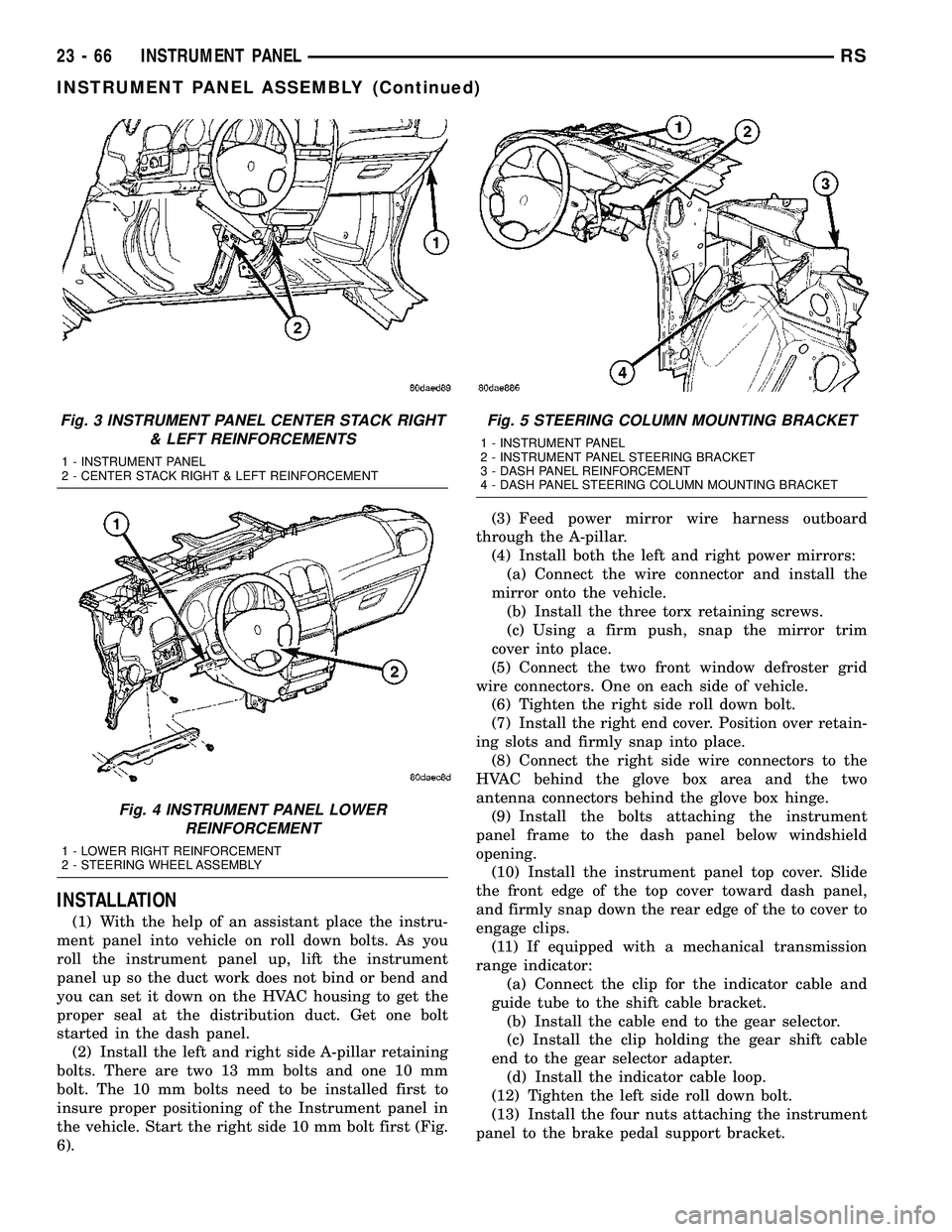
(1) With the help of an assistant place the instru-
ment panel into vehicle on roll down bolts. As you
roll the instrument panel up, lift the instrument
panel up so the duct work does not bind or bend and
you can set it down on the HVAC housing to get the
proper seal at the distribution duct. Get one bolt
started in the dash panel.
(2) Install the left and right side A-pillar retaining
bolts. There are two 13 mm bolts and one 10 mm
bolt. The 10 mm bolts need to be installed first to
insure proper positioning of the Instrument panel in
the vehicle. Start the right side 10 mm bolt first (Fig.
6).(3) Feed power mirror wire harness outboard
through the A-pillar.
(4) Install both the left and right power mirrors:
(a) Connect the wire connector and install the
mirror onto the vehicle.
(b) Install the three torx retaining screws.
(c) Using a firm push, snap the mirror trim
cover into place.
(5) Connect the two front window defroster grid
wire connectors. One on each side of vehicle.
(6) Tighten the right side roll down bolt.
(7) Install the right end cover. Position over retain-
ing slots and firmly snap into place.
(8) Connect the right side wire connectors to the
HVAC behind the glove box area and the two
antenna connectors behind the glove box hinge.
(9) Install the bolts attaching the instrument
panel frame to the dash panel below windshield
opening.
(10) Install the instrument panel top cover. Slide
the front edge of the top cover toward dash panel,
and firmly snap down the rear edge of the to cover to
engage clips.
(11) If equipped with a mechanical transmission
range indicator:
(a) Connect the clip for the indicator cable and
guide tube to the shift cable bracket.
(b) Install the cable end to the gear selector.
(c) Install the clip holding the gear shift cable
end to the gear selector adapter.
(d) Install the indicator cable loop.
(12) Tighten the left side roll down bolt.
(13) Install the four nuts attaching the instrument
panel to the brake pedal support bracket.
Fig. 3 INSTRUMENT PANEL CENTER STACK RIGHT
& LEFT REINFORCEMENTS
1 - INSTRUMENT PANEL
2 - CENTER STACK RIGHT & LEFT REINFORCEMENT
Fig. 4 INSTRUMENT PANEL LOWER
REINFORCEMENT
1 - LOWER RIGHT REINFORCEMENT
2 - STEERING WHEEL ASSEMBLY
Fig. 5 STEERING COLUMN MOUNTING BRACKET
1 - INSTRUMENT PANEL
2 - INSTRUMENT PANEL STEERING BRACKET
3 - DASH PANEL REINFORCEMENT
4 - DASH PANEL STEERING COLUMN MOUNTING BRACKET
23 - 66 INSTRUMENT PANELRS
INSTRUMENT PANEL ASSEMBLY (Continued)
Page 2189 of 2585
HEADLINER
REMOVAL
(1) Remove sun visors and vanity mirrors.
(2) Remove sun visor center supports.
(3) If equipped, remove coat hooks.
(4) If equipped, remove roof rail modules.
(5) Remove A-pillar trim covers.
(6) Remove B-pillar upper trim covers.
(7) Remove C-pillar upper trim covers.
(8) Remove D-pillar trim covers.
(9) Remove liftgate opening header trim.
(10) If equipped, remove overhead console screw.
(11) If equipped, remove reading lamp.
(12) Remove dome lamp.
(13) Remove push in locking fasteners attaching
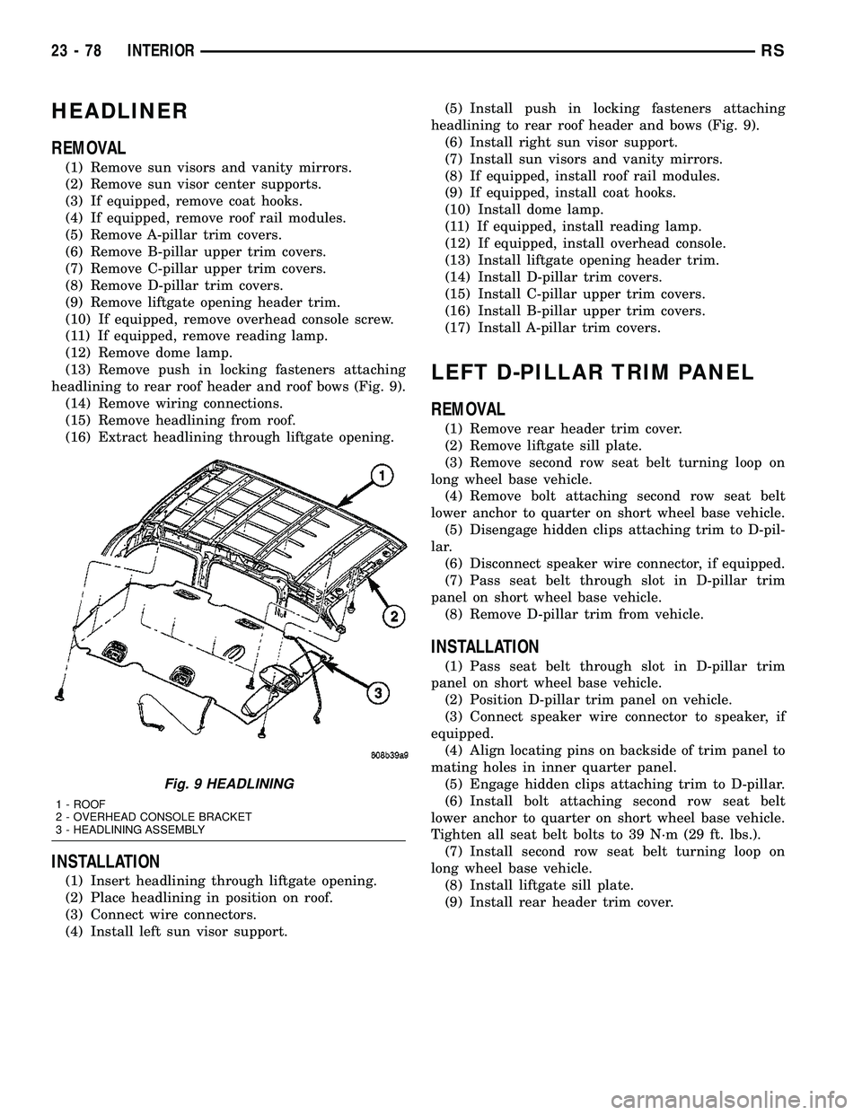
headlining to rear roof header and roof bows (Fig. 9).
(14) Remove wiring connections.
(15) Remove headlining from roof.
(16) Extract headlining through liftgate opening.
INSTALLATION
(1) Insert headlining through liftgate opening.
(2) Place headlining in position on roof.
(3) Connect wire connectors.
(4) Install left sun visor support.(5) Install push in locking fasteners attaching
headlining to rear roof header and bows (Fig. 9).
(6) Install right sun visor support.
(7) Install sun visors and vanity mirrors.
(8) If equipped, install roof rail modules.
(9) If equipped, install coat hooks.
(10) Install dome lamp.
(11) If equipped, install reading lamp.
(12) If equipped, install overhead console.
(13) Install liftgate opening header trim.
(14) Install D-pillar trim covers.
(15) Install C-pillar upper trim covers.
(16) Install B-pillar upper trim covers.
(17) Install A-pillar trim covers.
LEFT D-PILLAR TRIM PANEL
REMOVAL
(1) Remove rear header trim cover.
(2) Remove liftgate sill plate.
(3) Remove second row seat belt turning loop on
long wheel base vehicle.
(4) Remove bolt attaching second row seat belt
lower anchor to quarter on short wheel base vehicle.
(5) Disengage hidden clips attaching trim to D-pil-
lar.
(6) Disconnect speaker wire connector, if equipped.
(7) Pass seat belt through slot in D-pillar trim
panel on short wheel base vehicle.
(8) Remove D-pillar trim from vehicle.
INSTALLATION
(1) Pass seat belt through slot in D-pillar trim
panel on short wheel base vehicle.
(2) Position D-pillar trim panel on vehicle.
(3) Connect speaker wire connector to speaker, if
equipped.
(4) Align locating pins on backside of trim panel to
mating holes in inner quarter panel.
(5) Engage hidden clips attaching trim to D-pillar.
(6) Install bolt attaching second row seat belt
lower anchor to quarter on short wheel base vehicle.
Tighten all seat belt bolts to 39 N´m (29 ft. lbs.).
(7) Install second row seat belt turning loop on
long wheel base vehicle.
(8) Install liftgate sill plate.
(9) Install rear header trim cover.
Fig. 9 HEADLINING
1 - ROOF
2 - OVERHEAD CONSOLE BRACKET
3 - HEADLINING ASSEMBLY
23 - 78 INTERIORRS
Page 2190 of 2585
LIFTGATE SILL PLATE
REMOVAL
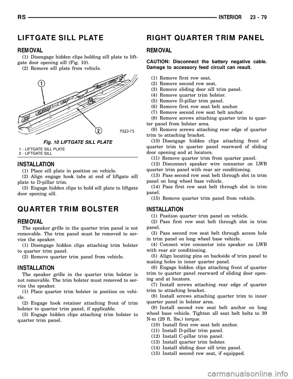
(1) Disengage hidden clips holding sill plate to lift-
gate door opening sill (Fig. 10).
(2) Remove sill plate from vehicle.
INSTALLATION
(1) Place sill plate in position on vehicle.
(2) Align engage hook tabs at end of liftgate sill
plate to D-pillar trim.
(3) Engage hidden clips to hold sill plate to liftgate
door opening sill.
QUARTER TRIM BOLSTER
REMOVAL
The speaker grille in the quarter trim panel is not
removable. The trim panel must be removed to ser-
vice the speaker.
(1) Disengage hidden clips attaching trim bolster
to quarter trim panel.
(2) Remove quarter trim panel from vehicle.
INSTALLATION
The speaker grille in the quarter trim bolster is
not removable. The trim bolster must removed to ser-
vice the speaker.
(1) Place quarter trim bolster in position on vehi-
cle.
(2) Engage hook retainer attaching front of trim
bolster to quarter trim panel, if applicable.
(3) Engage hidden clips attaching trim bolster to
quarter trim panel.
RIGHT QUARTER TRIM PANEL
REMOVAL
CAUTION: Disconnect the battery negative cable.
Damage to accessory feed circuit can result.
(1) Remove first row seat.
(2) Remove second row seat.
(3) Remove sliding door sill trim panel.
(4) Remove quarter trim bolster.
(5) Remove D-pillar trim panel.
(6) Remove first row seat belt anchor.
(7) Remove second row seat belt anchor.
(8) Remove screws attaching quarter trim to quar-
ter panel from bolster area.
(9) Remove screws attaching rear edge of quarter
trim to attaching bracket.
(10) Disengage hidden clips attaching front of
quarter trim to quarter panel rearward of sliding
door opening and at locators.
(11) Remove quarter trim from quarter panel.
(12) Disconnect speaker wire connector on LWB
quarter trim panel with rear air conditioning.
(13) Pass second row seat belt through slot in trim
panel on long wheel base vehicle.
(14) Pass first row seat belt through slot in trim
panel.
(15) Remove quarter trim panel from vehicle.
INSTALLATION
(1) Position quarter trim panel on vehicle.
(2) Pass first row seat belt through slot in trim
panel.
(3) Pass second row seat belt through access hole
in trim panel on long wheel base vehicle.
(4) Connect wire connector into speaker on LWB
with rear air conditioning.
(5) Align locating pins on backside of trim panel to
mating holes in inner quarter panel.
(6) Engage hidden clips attaching front of quarter
trim to quarter panel rearward of sliding door open-
ing and at locators.
(7) Install screws attaching rear edge of quarter
trim to attaching bracket.
(8) Install screws attaching quarter trim to inner
quarter panel in bolster area.
(9) Install second row seat belt anchor on long
wheel base vehicle. Tighten all seat belt bolts to 39
N´m (29 ft. lbs.) torque.
(10) Install first row seat belt anchor.
(11) Install D-pillar trim panel.
(12) Install C-pillar trim panel.
(13) Install quarter trim bolster.
(14) Install sliding door sill trim panel.
(15) Install second row seat, if equipped.
Fig. 10 LIFTGATE SILL PLATE
1 - LIFTGATE SILL PLATE
2 - LIFTGATE SILL
RSINTERIOR23-79
Page 2191 of 2585
(16) Install first row seat.
(17) Connect the battery negative cable.
LEFT QUARTER TRIM PANEL
REMOVAL
CAUTION: Disconnect the negative cable clamp
from battery post. Damage to accessory feed circuit
can result.
(1) Remove first row seat.
(2) Remove second row seat, if equipped.
(3) Remove front door sill plate on three door vehi-
cle.
(4) Remove sliding door sill plate on four door
vehicle.
(5) Remove left quarter trim bolster.
(6) Remove C-pillar trim panel.
(7) Remove left D-pillar trim panel.
(8) Remove first row seat belt anchor.
(9) Remove second row seat belt anchor on long
wheel base vehicle.
(10) Remove screws attaching quarter trim to
quarter panel from bolster area.
(11) Remove screws attaching rear edge of quarter
trim to attaching bracket or inner quarter trim
panel.
(12) Disconnect wire connector from accessory
power outlet, if equipped.
(13) Remove quarter trim from quarter panel.
(14) Pass front seat belt and turning loop through
slot in quarter trim panel on three door vehicle.
(15) Pass first row seat belt through slot in quar-
ter trim panel.
(16) Pass second row seat belt, if equipped,
through slot in quarter trim panel on long wheel
base vehicle.
(17) Remove quarter trim panel from vehicle.
INSTALLATION
(1) Position quarter trim panel on vehicle.
(2) Pass second row seat belt, if equipped, through
slot in quarter trim panel on long wheel base vehicle.
(3) Pass first row seat belt through slot in quarter
trim panel.
(4) Connect wire connector into accessory power
outlet, if equipped.
(5) Align locating pins on backside of trim panel to
mating holes in inner panels.
(6) Position quarter trim panel on inner quarter
panel.
(7) Install screws attaching rear edge of quarter
trim to attaching bracket or inner quarter panel.
(8) Install screws attaching quarter trim to inner
quarter panel in bolster area.(9) Install second row seat belts anchor on long
wheel base vehicle. Tighten all seat belt bolts to 39
N´m (28 in. lbs.) torque.
(10) Install first row seat belt anchor.
(11) Install left D-pillar trim panel.
(12) Install C-pillar trim panel.
(13) Install upper left B-pillar trim on three door
vehicle.
(14) Install left quarter trim bolster.
(15) Install front door sill plate on three door vehi-
cle.
(16) Install sliding door sill plate on four door
vehicle.
(17) Install second row seat, if equipped.
(18) Install first row seat.
(19) Connect the battery negative cable.
REAR HEADER TRIM
REMOVAL
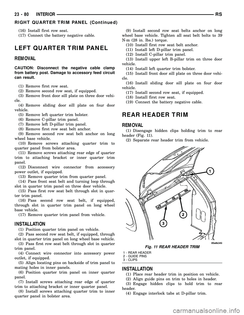
(1) Disengage hidden clips holding trim to rear
header (Fig. 11).
(2) Separate rear header trim from vehicle.
INSTALLATION
(1) Place rear header trim in position on vehicle.
(2) Align guide pins on trim to holes in header.
(3) Engage hidden clips to hold trim to rear
header.
(4) Engage interlock tabs at D-pillar trim.
Fig. 11 REAR HEADER TRIM
1 - REAR HEADER
2 - GUIDE PINS
3 - CLIPS
23 - 80 INTERIORRS
RIGHT QUARTER TRIM PANEL (Continued)
Page 2193 of 2585
INSTALLATION
(1) Position D-pillar trim on vehicle.
(2) Pass second row seat belt, if equipped, through
slot in trim panel on short wheel base vehicle.
(3) Connect speaker wire connector to speaker, if
equipped.
(4) Align locating pins on backside of trim panel to
mating holes in D-pillar.
(5) Engage hidden clips attaching trim to D-pillar.
(6) Install screws attaching trim panel to attach-
ing bracket on short wheel base vehicle.
(7) Install quarter trim bolster on short wheel base
vehicle.
(8) Install bolt to attach second row seat belt, if
equipped, anchor to quarter on short wheel base
vehicle. Tighten all seat belt bolts to 39 N´m (29 ft.
lbs.) torque.
(9) Install second row seat belt turning loop on
long wheel base vehicle.
(10) Install liftgate sill plate.
(11) Install rear header trim cover.
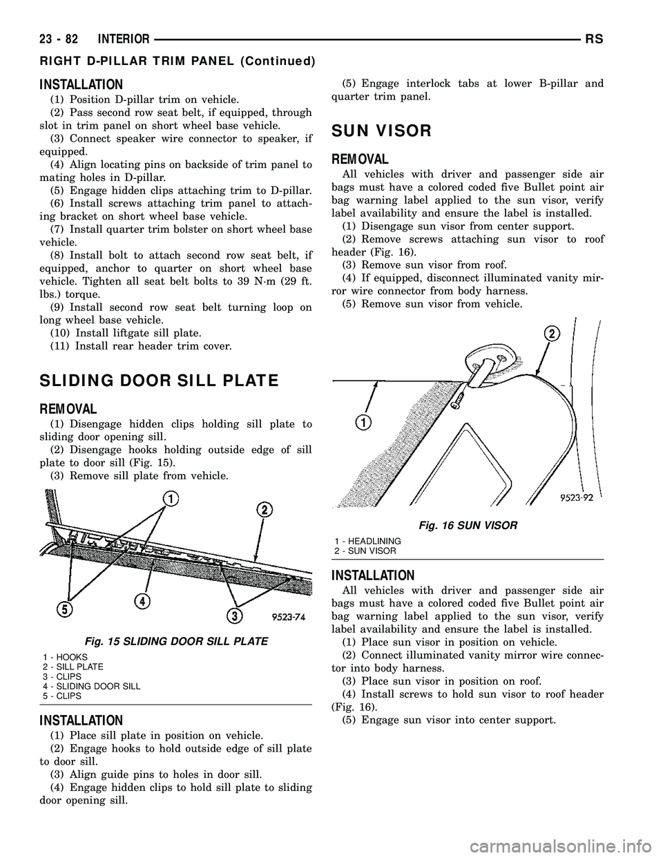
SLIDING DOOR SILL PLATE
REMOVAL
(1) Disengage hidden clips holding sill plate to
sliding door opening sill.
(2) Disengage hooks holding outside edge of sill
plate to door sill (Fig. 15).
(3) Remove sill plate from vehicle.
INSTALLATION
(1) Place sill plate in position on vehicle.
(2) Engage hooks to hold outside edge of sill plate
to door sill.
(3) Align guide pins to holes in door sill.
(4) Engage hidden clips to hold sill plate to sliding
door opening sill.(5) Engage interlock tabs at lower B-pillar and
quarter trim panel.
SUN VISOR
REMOVAL
All vehicles with driver and passenger side air
bags must have a colored coded five Bullet point air
bag warning label applied to the sun visor, verify
label availability and ensure the label is installed.
(1) Disengage sun visor from center support.
(2) Remove screws attaching sun visor to roof
header (Fig. 16).
(3) Remove sun visor from roof.
(4) If equipped, disconnect illuminated vanity mir-
ror wire connector from body harness.
(5) Remove sun visor from vehicle.
INSTALLATION
All vehicles with driver and passenger side air
bags must have a colored coded five Bullet point air
bag warning label applied to the sun visor, verify
label availability and ensure the label is installed.
(1) Place sun visor in position on vehicle.
(2) Connect illuminated vanity mirror wire connec-
tor into body harness.
(3) Place sun visor in position on roof.
(4) Install screws to hold sun visor to roof header
(Fig. 16).
(5) Engage sun visor into center support.
Fig. 15 SLIDING DOOR SILL PLATE
1 - HOOKS
2 - SILL PLATE
3 - CLIPS
4 - SLIDING DOOR SILL
5 - CLIPS
Fig. 16 SUN VISOR
1 - HEADLINING
2 - SUN VISOR
23 - 82 INTERIORRS
RIGHT D-PILLAR TRIM PANEL (Continued)
Page 2446 of 2585
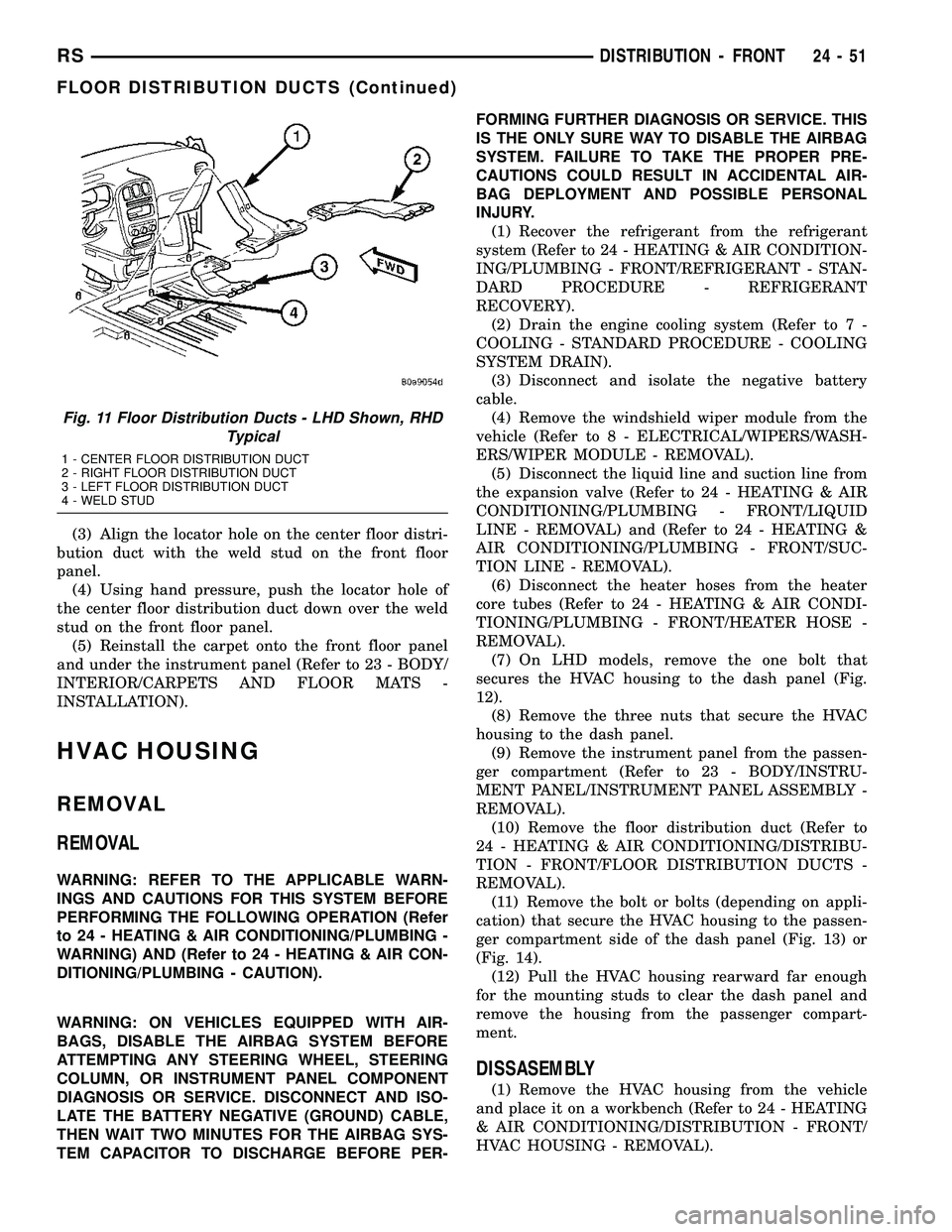
(3) Align the locator hole on the center floor distri-
bution duct with the weld stud on the front floor
panel.
(4) Using hand pressure, push the locator hole of
the center floor distribution duct down over the weld
stud on the front floor panel.
(5) Reinstall the carpet onto the front floor panel
and under the instrument panel (Refer to 23 - BODY/
INTERIOR/CARPETS AND FLOOR MATS -
INSTALLATION).
HVAC HOUSING
REMOVAL
REMOVAL
WARNING: REFER TO THE APPLICABLE WARN-
INGS AND CAUTIONS FOR THIS SYSTEM BEFORE
PERFORMING THE FOLLOWING OPERATION (Refer
to 24 - HEATING & AIR CONDITIONING/PLUMBING -
WARNING) AND (Refer to 24 - HEATING & AIR CON-
DITIONING/PLUMBING - CAUTION).
WARNING: ON VEHICLES EQUIPPED WITH AIR-
BAGS, DISABLE THE AIRBAG SYSTEM BEFORE
ATTEMPTING ANY STEERING WHEEL, STEERING
COLUMN, OR INSTRUMENT PANEL COMPONENT
DIAGNOSIS OR SERVICE. DISCONNECT AND ISO-
LATE THE BATTERY NEGATIVE (GROUND) CABLE,
THEN WAIT TWO MINUTES FOR THE AIRBAG SYS-
TEM CAPACITOR TO DISCHARGE BEFORE PER-FORMING FURTHER DIAGNOSIS OR SERVICE. THIS
IS THE ONLY SURE WAY TO DISABLE THE AIRBAG
SYSTEM. FAILURE TO TAKE THE PROPER PRE-
CAUTIONS COULD RESULT IN ACCIDENTAL AIR-
BAG DEPLOYMENT AND POSSIBLE PERSONAL
INJURY.
(1) Recover the refrigerant from the refrigerant
system (Refer to 24 - HEATING & AIR CONDITION-
ING/PLUMBING - FRONT/REFRIGERANT - STAN-
DARD PROCEDURE - REFRIGERANT
RECOVERY).
(2) Drain the engine cooling system (Refer to 7 -
COOLING - STANDARD PROCEDURE - COOLING
SYSTEM DRAIN).
(3) Disconnect and isolate the negative battery
cable.
(4) Remove the windshield wiper module from the
vehicle (Refer to 8 - ELECTRICAL/WIPERS/WASH-
ERS/WIPER MODULE - REMOVAL).
(5) Disconnect the liquid line and suction line from
the expansion valve (Refer to 24 - HEATING & AIR
CONDITIONING/PLUMBING - FRONT/LIQUID
LINE - REMOVAL) and (Refer to 24 - HEATING &
AIR CONDITIONING/PLUMBING - FRONT/SUC-
TION LINE - REMOVAL).
(6) Disconnect the heater hoses from the heater
core tubes (Refer to 24 - HEATING & AIR CONDI-
TIONING/PLUMBING - FRONT/HEATER HOSE -
REMOVAL).
(7) On LHD models, remove the one bolt that
secures the HVAC housing to the dash panel (Fig.
12).
(8) Remove the three nuts that secure the HVAC
housing to the dash panel.
(9) Remove the instrument panel from the passen-
ger compartment (Refer to 23 - BODY/INSTRU-
MENT PANEL/INSTRUMENT PANEL ASSEMBLY -
REMOVAL).
(10) Remove the floor distribution duct (Refer to
24 - HEATING & AIR CONDITIONING/DISTRIBU-
TION - FRONT/FLOOR DISTRIBUTION DUCTS -
REMOVAL).
(11) Remove the bolt or bolts (depending on appli-
cation) that secure the HVAC housing to the passen-
ger compartment side of the dash panel (Fig. 13) or
(Fig. 14).
(12) Pull the HVAC housing rearward far enough
for the mounting studs to clear the dash panel and
remove the housing from the passenger compart-
ment.
DISSASEMBLY
(1) Remove the HVAC housing from the vehicle
and place it on a workbench (Refer to 24 - HEATING
& AIR CONDITIONING/DISTRIBUTION - FRONT/
HVAC HOUSING - REMOVAL).
Fig. 11 Floor Distribution Ducts - LHD Shown, RHD
Typical
1 - CENTER FLOOR DISTRIBUTION DUCT
2 - RIGHT FLOOR DISTRIBUTION DUCT
3 - LEFT FLOOR DISTRIBUTION DUCT
4 - WELD STUD
RSDISTRIBUTION - FRONT24-51
FLOOR DISTRIBUTION DUCTS (Continued)
Page 2449 of 2585
housing half to the lower half. Tighten the screws to
2 N´m (17 in. lbs.).
(3) Position the upper air inlet housing onto the
top of the HVAC housing over the recirculation air
door and the blower motor and wheel. Be certain
that the upper pivot of the recirculation air door is
captured in the pivot receptacle of the upper air inlet
housing.
(4) Install the three screws that secure the upper
air inlet housing to the top of the HVAC housing. Be
certain to install the screw located just inside the
inboard side of the fresh air intake opening. Tighten
the screws to 2 N´m (17 in. lbs.).
(5) Install the two screws that secure the upper air
inlet housing to the lower air inlet housing. Tighten
the screws to 2 N´m (17 in. lbs.).
(6) Engage the two hook retainers on the bottom of
the distribution housing to the two receptacles on the
HVAC housing.
(7) Roll the top of the distribution housing up into
position against the HVAC housing.
(8) Install the three screws that secure the top of
the distribution housing to HVAC housing. Tighten
the screws to 2 N´m (17 in. lbs.).
(9) Engage the HVAC wire harness in the routing
clips molded into the outside of the HVAC housing.
(10) Reconnect the HVAC wire harness connector
to the blower motor.
(11) Install the expansion valve onto the evapora-
tor inlet and outlet tube fittings (Refer to 24 - HEAT-
ING & AIR CONDITIONING/PLUMBING - FRONT/
EXPANSION VALVE - INSTALLATION).
(12) Install a new foam seal onto the HVAC hous-
ing seal flange around the fresh air inlet opening and
the expansion valve/evaporator tube opening.
(13) Install the heater core tubes into the heater
core (Refer to 24 - HEATING & AIR CONDITION-
ING/PLUMBING - FRONT/HEATER CORE -
INSTALLATION - HEATER CORE TUBES).
(14) Install the HVAC housing into the vehicle
(Refer to 24 - HEATING & AIR CONDITIONING/
DISTRIBUTION - FRONT/HVAC HOUSING -
INSTALLATION).
INSTALLATION
(1) Position the HVAC housing into the passenger
compartment with the mounting studs located in
their proper mounting holes in the dash panel.(2) Install the bolt or bolts (depending on applica-
tion) that secure the HVAC housing to the passenger
compartment side of the dash panel. Tighten the
bolt(s) to 3 N´m (26 in. lbs.).
(3) Install the three nuts that secure the HVAC
housing to the engine compartment side of the dash
panel. Tighten the nuts to 7 N´m (62 in. lbs.).
(4) On LHD models, install the one bolt that
secures the HVAC housing to the engine compart-
ment side of the dash panel. Tighten the bolt to 4
N´m (35 in. lbs.).
(5) Reinstall the floor distribution duct (Refer to
24 - HEATING & AIR CONDITIONING/DISTRIBU-
TION - FRONT/FLOOR DISTRIBUTION DUCTS -
INSTALLATION).
(6) Install the instrument panel (Refer to 23 -
BODY/INSTRUMENT PANEL/INSTRUMENT
PANEL ASSEMBLY - INSTALLATION).
(7) Reconnect the heater hoses to the heater core
tubes (Refer to 24 - HEATING & AIR CONDITION-
ING/PLUMBING - FRONT/HEATER HOSE -
INSTALLATION).
(8) Reconnect the suction line and liquid line to
the expansion valve (Refer to 24 - HEATING & AIR
CONDITIONING/PLUMBING - FRONT/SUCTION
LINE - INSTALLATION) and (Refer to 24 - HEAT-
ING & AIR CONDITIONING/PLUMBING - FRONT/
LIQUID LINE - INSTALLATION).
(9) Install the windshield wiper module (Refer to 8
- ELECTRICAL/WIPERS/WASHERS/WIPER MOD-
ULE - INSTALLATION).
(10) Reconnect the negative battery cable.
(11) Refill the engine cooling system (Refer to 7 -
COOLING - STANDARD PROCEDURE - COOLING
SYSTEM REFILL).
(12) Evacuate the refrigerant system (Refer to 24 -
HEATING & AIR CONDITIONING/PLUMBING -
FRONT/REFRIGERANT - STANDARD PROCE-
DURE - REFRIGERANT SYSTEM EVACUATE).
(13) Charge the refrigerant system (Refer to 24 -
HEATING & AIR CONDITIONING/PLUMBING -
FRONT/REFRIGERANT - STANDARD PROCE-
DURE - REFRIGERANT SYSTEM CHARGE).
24 - 54 DISTRIBUTION - FRONTRS
HVAC HOUSING (Continued)