2004 CHRYSLER VOYAGER turn signal
[x] Cancel search: turn signalPage 1237 of 2585
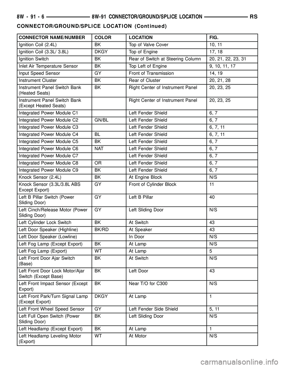
CONNECTOR NAME/NUMBER COLOR LOCATION FIG.
Ignition Coil (2.4L) BK Top of Valve Cover 10, 11
Ignition Coil (3.3L/ 3.8L) DKGY Top of Engine 17, 18
Ignition Switch BK Rear of Switch at Steering Column 20, 21, 22, 23, 31
Inlet Air Temperature Sensor BK Top Left of Engine 9, 10, 11, 17
Input Speed Sensor GY Front of Transmission 14, 19
Instrument Cluster BK Rear of Cluster 20, 21, 28
Instrument Panel Switch Bank
(Heated Seats)BK Right Center of Instrument Panel 20, 23, 25
Instrument Panel Switch Bank
(Except Heated Seats)Right Center of Instrument Panel 20, 23, 25
Integrated Power Module C1 Left Fender Shield 6, 7
Integrated Power Module C2 GN/BL Left Fender Shield 6, 7
Integrated Power Module C3 Left Fender Shield 6, 7, 11
Integrated Power Module C4 BL Left Fender Shield 6, 7, 11
Integrated Power Module C5 BK Left Fender Shield 6, 7
Integrated Power Module C6 NAT Left Fender Shield 6, 7
Integrated Power Module C7 Left Fender Shield 6, 7
Integrated Power Module C8 OR Left Fender Shield 6, 7
Integrated Power Module C9 BK Left Fender Shield 6, 7
Knock Sensor (2.4L) BK At Engine Block N/S
Knock Sensor (3.3L/3.8L ABS
Except Export)GY Front of Cylinder Block 11
Left B Pillar Switch (Power
Sliding Door)GY Left B Pillar 40
Left Cinch/Release Motor (Power
Sliding Door)GY Left Sliding Door N/S
Left Cylinder Lock Switch BK At Switch 43
Left Door Speaker (Highline) BK/RD At Speaker 43
Left Door Speaker (Lowline) In Door N/S
Left Fog Lamp (Except Export) BK At Lamp N/S
Left Fog Lamp (Export) WT At Lamp 5
Left Front Door Ajar Switch
(Base)BK At Switch N/S
Left Front Door Lock Motor/Ajar
Switch (Except Base)BK Left Door 43
Left Front Impact Sensor (Except
Export)BK Near T/O for C300 N/S
Left Front Park/Turn Signal Lamp
(Except Export)DKGY At Lamp 1
Left Front Wheel Speed Sensor GY Left Fender Side Shield 5, 11
Left Full Open Switch (Power
Sliding Door)BK Left Sliding Door N/S
Left Headlamp (Except Export) BK At Lamp 1
Left Headlamp Leveling Motor
(Export)WT At Motor N/S
8W - 91 - 6 8W-91 CONNECTOR/GROUND/SPLICE LOCATIONRS
CONNECTOR/GROUND/SPLICE LOCATION (Continued)
Page 1238 of 2585
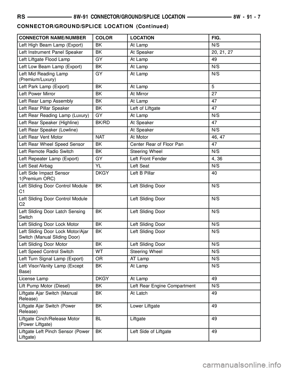
CONNECTOR NAME/NUMBER COLOR LOCATION FIG.
Left High Beam Lamp (Export) BK At Lamp N/S
Left Instrument Panel Speaker BK At Speaker 20, 21, 27
Left Liftgate Flood Lamp GY At Lamp 49
Left Low Beam Lamp (Export) BK At Lamp N/S
Left Mid Reading Lamp
(Premium/Luxury)GY At Lamp N/S
Left Park Lamp (Export) BK At Lamp 5
Left Power Mirror BK At Mirror 27
Left Rear Lamp Assembly BK At Lamp 47
Left Rear Pillar Speaker BK Left of Liftgate 47
Left Rear Reading Lamp (Luxury) GY At Lamp N/S
Left Rear Speaker (Highline) BK/RD At Speaker 47
Left Rear Speaker (Lowline) At Speaker N/S
Left Rear Vent Motor NAT At Motor 46, 47
Left Rear Wheel Speed Sensor BK Center Rear of Floor Pan 47
Left Remote Radio Switch BK Steering Wheel N/S
Left Repeater Lamp (Export) GY Left Front Fender 4, 36
Left Seat Airbag YL Left Seat N/S
Left Side Impact Sensor
1(Premium ORC)DKGY Left B Pillar 40
Left Sliding Door Control Module
C1BK Left Sliding Door N/S
Left Sliding Door Control Module
C2Left Sliding Door N/S
Left Sliding Door Latch Sensing
SwitchBK Left Sliding Door N/S
Left Sliding Door Lock Motor BK Left Sliding Door N/S
Left Sliding Door Lock Motor/Ajar
Switch (Manual Sliding Door)BK Left Sliding Door N/S
Left Sliding Door Motor BK Left Sliding Door N/S
Left Speed Control Switch WT Steering Wheel N/S
Left Turn Signal Lamp (Export) OR AT Lamp N/S
Left Visor/Vanity Lamp (Except
Base)BK At Lamp N/S
License Lamp DKGY At Lamp 49
Lift Pump Motor (Diesel) BK Left Rear Engine Compartment N/S
Liftgate Ajar Switch (Manual
Release)BK At Latch 49
Liftgate Ajar Switch (Power
Release)BK Lower Liftgate 49
Liftgate Cinch/Release Motor
(Power Liftgate)BL Liftgate 49
Liftgate Left Pinch Sensor (Power
Liftgate)BK Left Side of Liftgate 49
RS8W-91 CONNECTOR/GROUND/SPLICE LOCATION8W-91-7
CONNECTOR/GROUND/SPLICE LOCATION (Continued)
Page 1242 of 2585
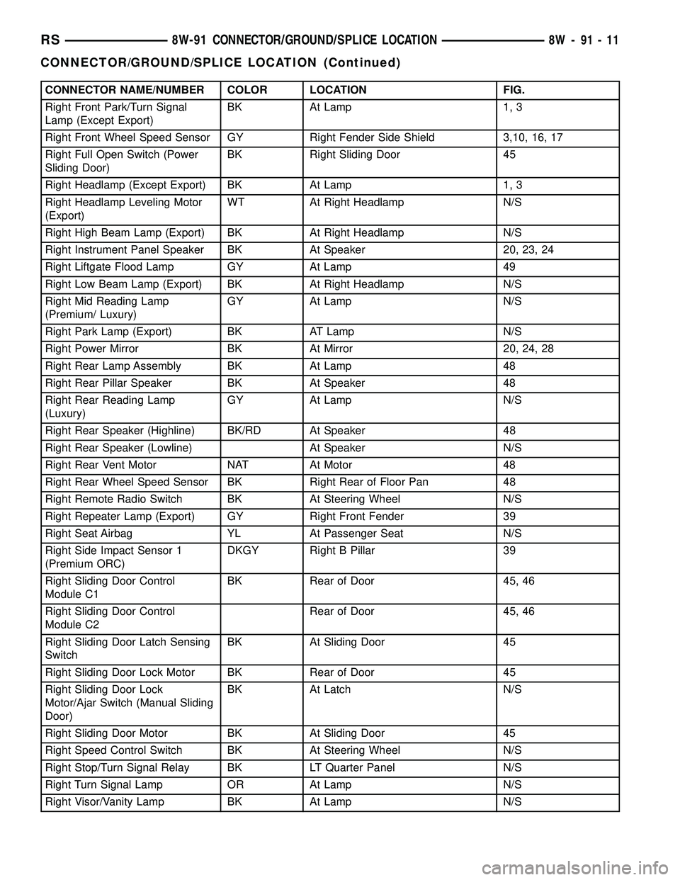
CONNECTOR NAME/NUMBER COLOR LOCATION FIG.
Right Front Park/Turn Signal
Lamp (Except Export)BK At Lamp 1, 3
Right Front Wheel Speed Sensor GY Right Fender Side Shield 3,10, 16, 17
Right Full Open Switch (Power
Sliding Door)BK Right Sliding Door 45
Right Headlamp (Except Export) BK At Lamp 1, 3
Right Headlamp Leveling Motor
(Export)WT At Right Headlamp N/S
Right High Beam Lamp (Export) BK At Right Headlamp N/S
Right Instrument Panel Speaker BK At Speaker 20, 23, 24
Right Liftgate Flood Lamp GY At Lamp 49
Right Low Beam Lamp (Export) BK At Right Headlamp N/S
Right Mid Reading Lamp
(Premium/ Luxury)GY At Lamp N/S
Right Park Lamp (Export) BK AT Lamp N/S
Right Power Mirror BK At Mirror 20, 24, 28
Right Rear Lamp Assembly BK At Lamp 48
Right Rear Pillar Speaker BK At Speaker 48
Right Rear Reading Lamp
(Luxury)GY At Lamp N/S
Right Rear Speaker (Highline) BK/RD At Speaker 48
Right Rear Speaker (Lowline) At Speaker N/S
Right Rear Vent Motor NAT At Motor 48
Right Rear Wheel Speed Sensor BK Right Rear of Floor Pan 48
Right Remote Radio Switch BK At Steering Wheel N/S
Right Repeater Lamp (Export) GY Right Front Fender 39
Right Seat Airbag YL At Passenger Seat N/S
Right Side Impact Sensor 1
(Premium ORC)DKGY Right B Pillar 39
Right Sliding Door Control
Module C1BK Rear of Door 45, 46
Right Sliding Door Control
Module C2Rear of Door 45, 46
Right Sliding Door Latch Sensing
SwitchBK At Sliding Door 45
Right Sliding Door Lock Motor BK Rear of Door 45
Right Sliding Door Lock
Motor/Ajar Switch (Manual Sliding
Door)BK At Latch N/S
Right Sliding Door Motor BK At Sliding Door 45
Right Speed Control Switch BK At Steering Wheel N/S
Right Stop/Turn Signal Relay BK LT Quarter Panel N/S
Right Turn Signal Lamp OR At Lamp N/S
Right Visor/Vanity Lamp BK At Lamp N/S
RS8W-91 CONNECTOR/GROUND/SPLICE LOCATION8W-91-11
CONNECTOR/GROUND/SPLICE LOCATION (Continued)
Page 1526 of 2585
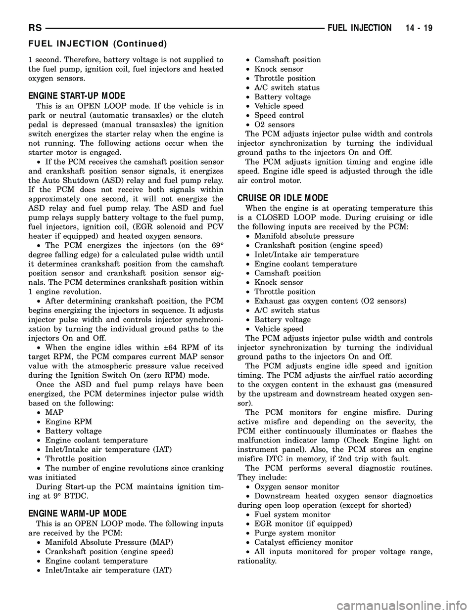
1 second. Therefore, battery voltage is not supplied to
the fuel pump, ignition coil, fuel injectors and heated
oxygen sensors.
ENGINE START-UP MODE
This is an OPEN LOOP mode. If the vehicle is in
park or neutral (automatic transaxles) or the clutch
pedal is depressed (manual transaxles) the ignition
switch energizes the starter relay when the engine is
not running. The following actions occur when the
starter motor is engaged.
²If the PCM receives the camshaft position sensor
and crankshaft position sensor signals, it energizes
the Auto Shutdown (ASD) relay and fuel pump relay.
If the PCM does not receive both signals within
approximately one second, it will not energize the
ASD relay and fuel pump relay. The ASD and fuel
pump relays supply battery voltage to the fuel pump,
fuel injectors, ignition coil, (EGR solenoid and PCV
heater if equipped) and heated oxygen sensors.
²The PCM energizes the injectors (on the 69É
degree falling edge) for a calculated pulse width until
it determines crankshaft position from the camshaft
position sensor and crankshaft position sensor sig-
nals. The PCM determines crankshaft position within
1 engine revolution.
²After determining crankshaft position, the PCM
begins energizing the injectors in sequence. It adjusts
injector pulse width and controls injector synchroni-
zation by turning the individual ground paths to the
injectors On and Off.
²When the engine idles within 64 RPM of its
target RPM, the PCM compares current MAP sensor
value with the atmospheric pressure value received
during the Ignition Switch On (zero RPM) mode.
Once the ASD and fuel pump relays have been
energized, the PCM determines injector pulse width
based on the following:
²MAP
²Engine RPM
²Battery voltage
²Engine coolant temperature
²Inlet/Intake air temperature (IAT)
²Throttle position
²The number of engine revolutions since cranking
was initiated
During Start-up the PCM maintains ignition tim-
ing at 9É BTDC.
ENGINE WARM-UP MODE
This is an OPEN LOOP mode. The following inputs
are received by the PCM:
²Manifold Absolute Pressure (MAP)
²Crankshaft position (engine speed)
²Engine coolant temperature
²Inlet/Intake air temperature (IAT)²Camshaft position
²Knock sensor
²Throttle position
²A/C switch status
²Battery voltage
²Vehicle speed
²Speed control
²O2 sensors
The PCM adjusts injector pulse width and controls
injector synchronization by turning the individual
ground paths to the injectors On and Off.
The PCM adjusts ignition timing and engine idle
speed. Engine idle speed is adjusted through the idle
air control motor.
CRUISE OR IDLE MODE
When the engine is at operating temperature this
is a CLOSED LOOP mode. During cruising or idle
the following inputs are received by the PCM:
²Manifold absolute pressure
²Crankshaft position (engine speed)
²Inlet/Intake air temperature
²Engine coolant temperature
²Camshaft position
²Knock sensor
²Throttle position
²Exhaust gas oxygen content (O2 sensors)
²A/C switch status
²Battery voltage
²Vehicle speed
The PCM adjusts injector pulse width and controls
injector synchronization by turning the individual
ground paths to the injectors On and Off.
The PCM adjusts engine idle speed and ignition
timing. The PCM adjusts the air/fuel ratio according
to the oxygen content in the exhaust gas (measured
by the upstream and downstream heated oxygen sen-
sor).
The PCM monitors for engine misfire. During
active misfire and depending on the severity, the
PCM either continuously illuminates or flashes the
malfunction indicator lamp (Check Engine light on
instrument panel). Also, the PCM stores an engine
misfire DTC in memory, if 2nd trip with fault.
The PCM performs several diagnostic routines.
They include:
²Oxygen sensor monitor
²Downstream heated oxygen sensor diagnostics
during open loop operation (except for shorted)
²Fuel system monitor
²EGR monitor (if equipped)
²Purge system monitor
²Catalyst efficiency monitor
²All inputs monitored for proper voltage range,
rationality.
RSFUEL INJECTION14-19
FUEL INJECTION (Continued)
Page 1528 of 2585
opposite preset limit or switch point. The process
then repeats itself in the opposite direction.
Short term fuel correction will keep increasing or
decreasing injector pulse-width based upon the
upstream O2 Sensor input. The maximum range of
authority for short term memory is 25% (+/-) of base
pulse-width. Short term is violated and is lost when
ignition is turned OFF.
Long Term
The second fuel correction program is the long
term adaptive memory. In order to maintain correct
emission throughout all operating ranges of the
engine, a cell structure based on engine rpm and load
(MAP) is used.
Ther number of cells varies upon the driving con-
ditions. Two cells are used only during idle, based
upon TPS and Park/Neutral switch inputs. There
may be two other cells used for deceleration, based
on TPS, engine rpm, and vehicle speed. The other
twelve cells represent a manifold pressure and an
rpm range. Six of the cells are high rpm and the
other six are low rpm. Each of these cells has a spe-
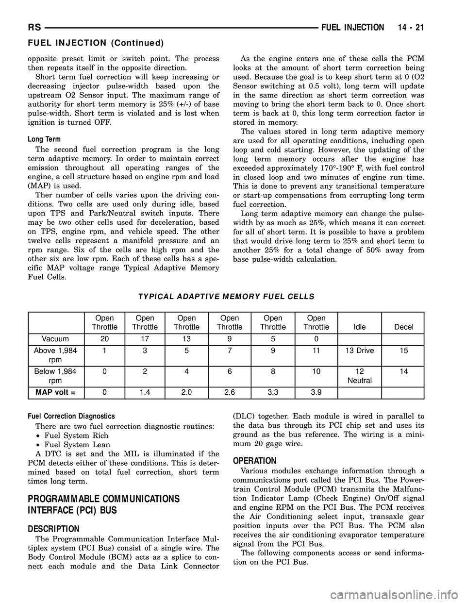
cific MAP voltage range Typical Adaptive Memory
Fuel Cells.As the engine enters one of these cells the PCM
looks at the amount of short term correction being
used. Because the goal is to keep short term at 0 (O2
Sensor switching at 0.5 volt), long term will update
in the same direction as short term correction was
moving to bring the short term back to 0. Once short
term is back at 0, this long term correction factor is
stored in memory.
The values stored in long term adaptive memory
are used for all operating conditions, including open
loop and cold starting. However, the updating of the
long term memory occurs after the engine has
exceeded approximately 170É-190É F, with fuel control
in closed loop and two minutes of engine run time.
This is done to prevent any transitional temperature
or start-up compensations from corrupting long term
fuel correction.
Long term adaptive memory can change the pulse-
width by as much as 25%, which means it can correct
for all of short term. It is possible to have a problem
that would drive long term to 25% and short term to
another 25% for a total change of 50% away from
base pulse-width calculation.
TYPICAL ADAPTIVE MEMORY FUEL CELLS
Open
ThrottleOpen
ThrottleOpen
ThrottleOpen
ThrottleOpen
ThrottleOpen
Throttle Idle Decel
Vacuum 20 17 13 9 5 0
Above 1,984
rpm1 3 5 7 9 11 13 Drive 15
Below 1,984
rpm02 4 6 8 1012
Neutral14
MAP volt =0 1.4 2.0 2.6 3.3 3.9
Fuel Correction Diagnostics
There are two fuel correction diagnostic routines:
²Fuel System Rich
²Fuel System Lean
A DTC is set and the MIL is illuminated if the
PCM detects either of these conditions. This is deter-
mined based on total fuel correction, short term
times long term.
PROGRAMMABLE COMMUNICATIONS
INTERFACE (PCI) BUS
DESCRIPTION
The Programmable Communication Interface Mul-
tiplex system (PCI Bus) consist of a single wire. The
Body Control Module (BCM) acts as a splice to con-
nect each module and the Data Link Connector(DLC) together. Each module is wired in parallel to
the data bus through its PCI chip set and uses its
ground as the bus reference. The wiring is a mini-
mum 20 gage wire.
OPERATION
Various modules exchange information through a
communications port called the PCI Bus. The Power-
train Control Module (PCM) transmits the Malfunc-
tion Indicator Lamp (Check Engine) On/Off signal
and engine RPM on the PCI Bus. The PCM receives
the Air Conditioning select input, transaxle gear
position inputs over the PCI Bus. The PCM also
receives the air conditioning evaporator temperature
signal from the PCI Bus.
The following components access or send informa-
tion on the PCI Bus.
RSFUEL INJECTION14-21
FUEL INJECTION (Continued)
Page 1537 of 2585
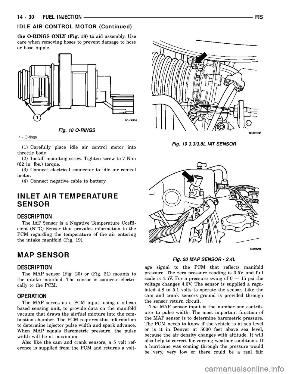
the O-RINGS ONLY (Fig. 18)to aid assembly. Use
care when removing hoses to prevent damage to hose
or hose nipple.
(1) Carefully place idle air control motor into
throttle body.
(2) Install mounting screw. Tighten screw to 7 N´m
(62 in. lbs.) torque.
(3) Connect electrical connector to idle air control
motor.
(4) Connect negative cable to battery.
INLET AIR TEMPERATURE
SENSOR
DESCRIPTION
The IAT Sensor is a Negative Temperature Coeffi-
cient (NTC) Sensor that provides information to the
PCM regarding the temperature of the air entering
the intake manifold (Fig. 19).
MAP SENSOR
DESCRIPTION
The MAP sensor (Fig. 20) or (Fig. 21) mounts to
the intake manifold. The sensor is connects electri-
cally to the PCM.
OPERATION
The MAP serves as a PCM input, using a silicon
based sensing unit, to provide data on the manifold
vacuum that draws the air/fuel mixture into the com-
bustion chamber. The PCM requires this information
to determine injector pulse width and spark advance.
When MAP equals Barometric pressure, the pulse
width will be at maximum.
Also like the cam and crank sensors, a 5 volt ref-
erence is supplied from the PCM and returns a volt-age signal to the PCM that reflects manifold
pressure. The zero pressure reading is 0.5V and full
scale is 4.5V. For a pressure swing of0Ð15psithe
voltage changes 4.0V. The sensor is supplied a regu-
lated 4.8 to 5.1 volts to operate the sensor. Like the
cam and crank sensors ground is provided through
the sensor return circuit.
The MAP sensor input is the number one contrib-
utor to pulse width. The most important function of
the MAP sensor is to determine barometric pressure.
The PCM needs to know if the vehicle is at sea level
or is it in Denver at 5000 feet above sea level,
because the air density changes with altitude. It will
also help to correct for varying weather conditions. If
a hurricane was coming through the pressure would
be very, very low or there could be a real fair
Fig. 18 O-RINGS
1 - O-rings
Fig. 19 3.3/3.8L IAT SENSOR
Fig. 20 MAP SENSOR - 2.4L
14 - 30 FUEL INJECTIONRS
IDLE AIR CONTROL MOTOR (Continued)
Page 1786 of 2585
OPERATION
The function of an accumulator is to cushion the
application of a frictional clutch element. When pres-
surized fluid is applied to a clutch circuit, the appli-
cation force is dampened by fluid collecting in the
respective accumulator chamber against the piston
and spring(s). The intended result is a smooth, firm
clutch application.
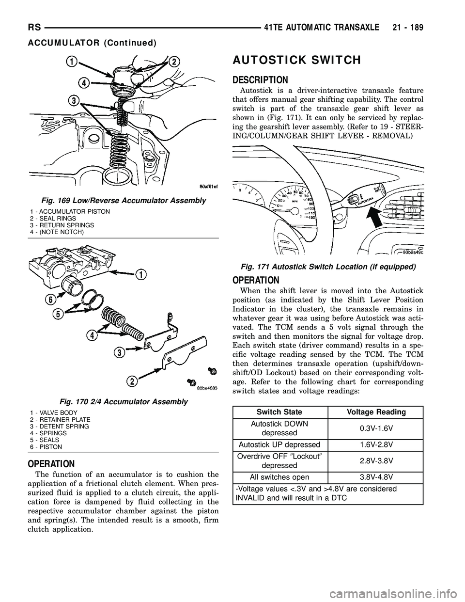
AUTOSTICK SWITCH
DESCRIPTION
Autostick is a driver-interactive transaxle feature
that offers manual gear shifting capability. The control
switch is part of the transaxle gear shift lever as
shown in (Fig. 171). It can only be serviced by replac-
ing the gearshift lever assembly. (Refer to 19 - STEER-
ING/COLUMN/GEAR SHIFT LEVER - REMOVAL)
OPERATION
When the shift lever is moved into the Autostick
position (as indicated by the Shift Lever Position
Indicator in the cluster), the transaxle remains in
whatever gear it was using before Autostick was acti-
vated. The TCM sends a 5 volt signal through the
switch and then monitors the signal for voltage drop.
Each switch state (driver command) results in a spe-
cific voltage reading sensed by the TCM. The TCM
then determines transaxle operation (upshift/down-
shift/OD Lockout) based on their corresponding volt-
age. Refer to the following chart for corresponding
switch states and voltage readings:
Switch State Voltage Reading
Autostick DOWN
depressed0.3V-1.6V
Autostick UP depressed 1.6V-2.8V
Overdrive OFF9Lockout9
depressed2.8V-3.8V
All switches open 3.8V-4.8V
-Voltage values <.3V and >4.8V are considered
INVALID and will result in a DTC
Fig. 169 Low/Reverse Accumulator Assembly
1 - ACCUMULATOR PISTON
2 - SEAL RINGS
3 - RETURN SPRINGS
4 - (NOTE NOTCH)
Fig. 170 2/4 Accumulator Assembly
1 - VALVE BODY
2 - RETAINER PLATE
3 - DETENT SPRING
4 - SPRINGS
5 - SEALS
6 - PISTON
Fig. 171 Autostick Switch Location (if equipped)
RS41TE AUTOMATIC TRANSAXLE21 - 189
ACCUMULATOR (Continued)
Page 2417 of 2585

erence signal and a sensor ground to the transducer,
then monitors the output voltage of the transducer
on a sensor return circuit to determine refrigerant
pressure. The PCM is programmed to respond to this
and other sensor inputs by controlling the operation
of the A/C compressor clutch and the radiator cooling
fan to help optimize air conditioning system perfor-
mance and to protect the system components from
damage. The A/C pressure transducer input to the
PCM will also prevent the A/C compressor clutch
from engaging when ambient temperatures are below
about 4.5É C (40É F) due to the pressure/temperature
relationship of the refrigerant. The Schrader-type
valve in the liquid line fitting permits the A/C pres-
sure transducer to be removed or installed without
disturbing the refrigerant in the system. The A/C
pressure transducer is diagnosed using a DRBIIIt
scan tool. Refer to Body Diagnostic Procedures.
DIAGNOSIS AND TESTING - A/C PRESSURE
TRANSDUCER
The A/C pressure transducer is tested using a
DRBIIItscan tool. Refer to the appropriate diagnos-
tic information. Before testing the A/C pressure
transducer, be certain that the transducer wire har-
ness connection is clean of corrosion and properly
connected. For the A/C to operate, an A/C pressure
transducer voltage reading between 0.451 and 4.519
volts is required. Voltages outside this range indicate
a low or high refrigerant system pressure condition
to the powertrain control module (PCM). The PCM is
programmed to respond to a low or high refrigerant
system pressure by suppressing operation of the A/C
compressor. Refer to the A/C Pressure Transducer
Voltage chart for the possible conditions indicated by
the transducer voltage reading.
A/C PRESSURE TRANSDUCER VOLTAGE
Voltage Possible Indication
0.0 1. No sensor supply voltage from
PCM.
2. Shorted sensor circuit.
3. Faulty transducer.
0.150 TO 0.450 1. Ambient temperature below 10É
C (50É F).
2. Low refrigerant system pressure.
0.451 TO 4.519 1. Normal refrigerant system
pressure.
4.520 TO 4.850 1. High refrigerant system pressure.
5.0 1. Open sensor circuit.
2. Faulty transducer.
REMOVAL
NOTE: Note: It is not necessary to discharge the
refrigerant system to replace the A/C pressure
transducer.
(1) Disconnect and isolate the battery negative
cable.
(2) Disconnect the wire harness connector from the
A/C pressure transducer (Fig. 10).
(3) Remove the A/C pressure transducer from the
fitting on the liquid line.
(4) Remove the O-ring seal from the A/C pressure
transducer fitting and discard.
INSTALLATION
NOTE: Replace the O-ring seal before installing the
A/C pressure transducer.
(1) Lubricate a new rubber O-ring seal with clean
refrigerant oil and install it on the A/C pressure
transducer fitting. Use only the specified O-rings as
they are made of a special material for the R-134a
system. Use only refrigerant oil of the type recom-
mended for the A/C compressor in the vehicle.
(2) Install and tighten the A/C pressure transducer
onto the fitting onto the liquid line fitting.
(3) Connect the wire harness connector to the A/C
pressure transducer.
(4) Reconnect the battery negative cable.
Fig. 10 A/C Pressure Transducer - Typical
1 - RIGHT FRONT STRUT TOWER
2 - WIRE HARNESS CONNECTOR
3 - A/C PRESSURE TRANSDUCER
4 - WIPER MODULE DRAIN TUBE
5 - HIGH SIDE SERVICE PORT
6 - LIQUID LINE
24 - 22 CONTROLS - FRONTRS
A/C PRESSURE TRANSDUCER (Continued)