Page 238 of 382

Checking the Fluid Level
Prepare your vehicle as follows:
·Park your vehicle on a level place. Keep the engine
running.
·With the parking brake applied, place the shift lever
in PARK (P).
·With your foot on the brake pedal, move the shift
lever through each gear range, pausing for about
three seconds in each range. Then, position the shift
lever in PARK (P).
·Let the engine run at idle for three minutes or more.
Then, without shutting off the engine, follow these steps:
The transmission dipstick
is located near the center
of the engine compartment
and will be labeled with
this graphic shown. See
Engine Compartment
Overview on page 5-12for
more information on
location.
·Flip the handle up and then pull out the dipstick and
wipe it with a clean rag or paper towel.
·Push it back in all the way, wait three seconds and
then pull it back out again.
·Check both sides of the dipstick, and read the lower
level. The ¯uid level must be in the COLD area for
a cold check or in the HOT area or cross-hatched
area for a hot check. Be sure to keep the dipstick
pointed down to get an accurate reading.
·If the ¯uid level is in the acceptable range, push the
dipstick back in all the way; then ¯ip the handle
down to lock the dipstick in place.
5-24
Page 239 of 382

How to Add Fluid
Refer to the Maintenance Schedule to determine what
kind of transmission ¯uid to use. SeePart D:
Recommended Fluids and Lubricants on page 6-30.
Using a funnel, add ¯uid down the transmission dipstick
tube only after checking the transmission ¯uid while it
is hot. (A cold check is used only as a reference.) If the
¯uid level is low, add only enough of the proper ¯uid
to bring the level up to the HOT area for a hot check. It
doesn't take much ¯uid, generally less than one pint
(0.5 L).
Don't over®ll.
Notice:We recommend you use only ¯uid labeled
DEXRONž-III, because ¯uid with that label is
made especially for your automatic transmission.
Damage caused by ¯uid other than DEXRON
ž-III is
not covered by your new vehicle warranty.
·After adding ¯uid, recheck the ¯uid level as
described under²How to Check.²
·When the correct ¯uid level is obtained, push the
dipstick back in all the way; then ¯ip the handle
down to lock the dipstick in place.
Engine Coolant
The cooling system in your vehicle is ®lled with
DEX-COOLžengine coolant. This coolant is designed
to remain in your vehicle for 5 years or 150,000 miles
(240 000 km), whichever occurs ®rst, if you add
only DEX-COOL
žextended life coolant.
The following explains your cooling system and how to
add coolant when it is low. If you have a problem
with engine overheating, see
Engine Overheating on
page 5-28.
A 50/50 mixture of clean, drinkable water and
DEX-COOL
žcoolant will:
·Give freezing protection down to-34ÉF (-37ÉC).
·Give boiling protection up to 265ÉF (129ÉC).
·Protect against rust and corrosion.
·Help keep the proper engine temperature.
·Let the warning lights and gages work as they
should.
Notice:Using coolant other than DEX-COOLžmay
cause premature engine, heater core or radiator
corrosion. In addition, the engine coolant may
require changing sooner, at 30,000 miles (50 000 km)
or 24 months, whichever occurs ®rst. Any repairs
would not be covered by your warranty. Always use
DEX-COOL
ž(silicate-free) coolant in your vehicle.
5-25
Page 250 of 382

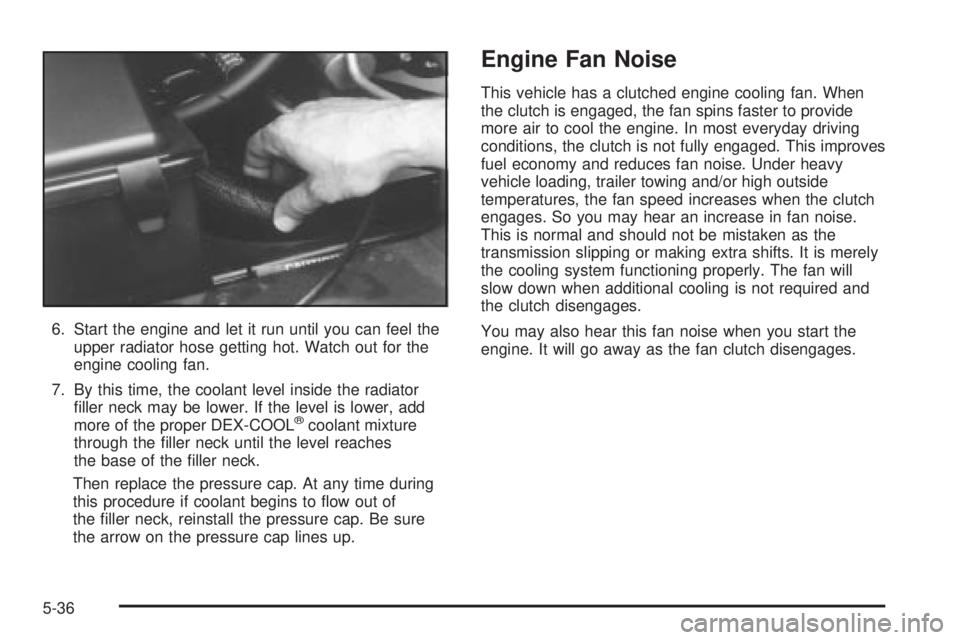
6. Start the engine and let it run until you can feel the
upper radiator hose getting hot. Watch out for the
engine cooling fan.
7. By this time, the coolant level inside the radiator
®ller neck may be lower. If the level is lower, add
more of the proper DEX-COOL
žcoolant mixture
through the ®ller neck until the level reaches
the base of the ®ller neck.
Then replace the pressure cap. At any time during
this procedure if coolant begins to ¯ow out of
the ®ller neck, reinstall the pressure cap. Be sure
the arrow on the pressure cap lines up.
Engine Fan Noise
This vehicle has a clutched engine cooling fan. When
the clutch is engaged, the fan spins faster to provide
more air to cool the engine. In most everyday driving
conditions, the clutch is not fully engaged. This improves
fuel economy and reduces fan noise. Under heavy
vehicle loading, trailer towing and/or high outside
temperatures, the fan speed increases when the clutch
engages. So you may hear an increase in fan noise.
This is normal and should not be mistaken as the
transmission slipping or making extra shifts. It is merely
the cooling system functioning properly. The fan will
slow down when additional cooling is not required and
the clutch disengages.
You may also hear this fan noise when you start the
engine. It will go away as the fan clutch disengages.
5-36
Page 257 of 382

Jump Starting
If your battery has run down, you may want to use
another vehicle and some jumper cables to start your
vehicle. But please follow the numbered steps to
do it safely.
{CAUTION:
Batteries can hurt you. They can be dangerous
because:
·They contain acid that can burn you.
·They contain gas that can explode or
ignite.
·They contain enough electricity to
burn you.
If you do not follow these steps exactly, some
or all of these things can hurt you.
Notice:Ignoring these steps could result in costly
damage to your vehicle that would not be covered
by your warranty.
Trying to start your vehicle by pushing or pulling it
will not work, and it could damage your vehicle.
1. Check the other vehicle. It must have a
12±-volt battery with a negative ground system.
Notice:If the other vehicle's system is not a 12-volt
system with a negative ground, both vehicles can
be damaged. Only use vehicles with 12-volt systems
with negative grounds to jump start your vehicle.
2. Get the vehicles close enough so the jumper cables
can reach, but be sure the vehicles aren't touching
each other. If they are, it could cause a ground
connection you don't want. You wouldn't be able to
start your vehicle, and the bad grounding could
damage the electrical systems.
To avoid the possibility of the vehicles rolling, set
the parking brake ®rmly on both vehicles involved in
the jump start procedure. Put an automatic
transmission in PARK (P) and a manual
transmission in NEUTRAL.
3. Turn off the ignition on both vehicles. Unplug
unnecessary accessories plugged into the cigarette
lighter or accessory power outlets. Turn off all
lamps that aren't needed as well as radios. This will
avoid sparks and help save both batteries. In
addition, it could save your radio!
5-43
Page 277 of 382

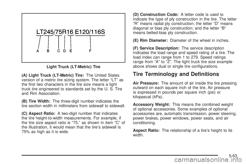
(A) Light Truck (LT-Metric) Tire:The United States
version of a metric tire sizing system. The letter ªLTº as
the ®rst two characters in the tire size means a light
truck tire engineered to standards set by the U. S. Tire
and Rim Association.
(B) Tire Width:The three-digit number indicates the
tire section width in millimeters from sidewall to sidewall.
(C) Aspect Ratio:A two-digit number that indicates
the tire height-to-width measurements. For example, if
the tire size aspect ratio is ª75,º as shown in item ªCº of
the illustration, it would mean that the tire's sidewall is
75% as high as it is wide.(D) Construction Code:A letter code is used to
indicate the type of ply construction in the tire. The letter
ªRº means radial ply construction; the letter ªDº means
diagonal or bias ply construction; and the letter ªBº
means belted-bias ply construction.
(E) Rim Diameter:Diameter of the wheel in inches.
(F) Service Description:The service description
indicates the load range and speed rating of a tire. The
load index can range from 1 to 279. Speed ratings
range from ªAº to ªZº. The light truck tire size example
above shows dual or single tire con®gurations.Tire Terminology and De®nitions
Air Pressure:The amount of air inside the tire pressing
outward on each square inch of the tire. Air pressure
is expressed in pounds per square inch (psi) or
kilopascal (kPa).
Accessory Weight:This means the combined weight
of optional accessories. Some examples of optional
accessories are, automatic transmission, power steering,
power brakes, power windows, power seats, and air
conditioning.
Aspect Ratio:The relationship of a tire's height to its
width. Light Truck (LT-Metric) Tire
5-63
Page 312 of 382

Fuse/Circuit
Breaker Usage
3 Courtesy Lamps, Glove Box Lamp,
Dome Reading Lamps, Vanity Mirror
Lamps, Courtesy Lamps
4 Daytime Running Lamps Relay,
Instrument Panel Cluster
5 Rear Defogger
6 Cruise Module, Truck Body Control
Module, Instrument Panel Cluster,
Cruise Control Switch,
Electrochromic Mirror
7 Power Outlets, Subwoofer Ampli®er
8 Crank Circuit Fuse, Park/Neutral
Switch, Starter Enabler Relay
9 License Plate Lamp, Tailamps,
Parking Lamps, Ashtray Lamp,
Panel Lights, Trailer Taillamps, Front
and Rear Sidemarker Lamps, Door
Switch Illumination, Headlamp
Switch Illumination, Rear Seat Audio
Illumination, Truck Body Control
Module
10 Air Bag System
11 Not UsedFuse/Circuit
Breaker Usage
12 Blower Motor, Rear Air Conditioning
Relay Coil, Front Cont. Temp. Door
Motor, HI Blower Relay, Defogger
Timer Coil
13 Cigarette Lighter, Door Lock
Switches, Dutch Door Release
Module
14 Cluster Illumination, Climate
Controls, Chime Module, Radio
Illumination, Rear Heat Switch
Illumination, Rear Wiper/Washer
Switch Illumination, Rear Liftgate
Switch Illumination, Remote
Cassette Illumination, Overhead
Console, Truck Body Control
Illumination
15 Truck Body Module, Headlamp
Relay
16 Front Turn Signals, Rear Turn
Signals, Trailer Turn Signals,
Back-Up Lamps, Brake
Transmission Shift Interlock Solenoid
17 Front Wipers, Front Washer Pump
5-98
Page 316 of 382
Capacities and Speci®cations
Please refer toPart D: Recommended Fluids and Lubricants on page 6-30for more information. See refrigerant
charge label under the hood for charge capacity information and requirements.
Engine Speci®cations
Engine RPO Transmission Spark Plug Gap Firing Order
ªVortecº 4300 V6 MFI* LU3 M300.060 inches
(1.52 mm)1±6±5±4±3±2
*Micro Fuel Injection
Tire Pressures ± See
Loading Your Vehicle on page 4-30.
ApplicationCapacities
English Metric
Wheel Nut Torque 140 lb ft 190 N m
Tire PressureSee certi®cate and tire insert label on rear of the
driver's side door.
5-102
Page 317 of 382
Capacities and Speci®cations
ApplicationCapacities
English Metric
Cooling Capacities
Quantity without Rear Heater
Quantity with Rear Heater13.5 quarts
16.5 quarts12.8 L
15.6 L
Engine Oil with Filter 4.5 quarts 4.3 L
Fuel Tank 27.0 gallons 101.8 L
Transmission Fluid (Drain and Re®ll) 5.0 quarts 4.7 L
Differential Fluid
Front Axle
Rear Axle2.6 pints
3.5 pints1.2 L
1.7 L
Refrigerant Type 134a
Front A/C
Front and Rear A/C2.25 lbs.
3.0 lbs.1.02 kg
1.36 kg
All capacities are approximate. When adding, be sure to ®ll to the appropriate level, as recommended in this
manual. recheck the ¯uid level after ®lling. See
Part D: Recommended Fluids and Lubricants on page 6-30for
more information.
5-103