2004 BMW Z4 ROADSTER 3.0I steering
[x] Cancel search: steeringPage 43 of 120
Reference
At a glance
Controls
Driving tips
Mobility
41
Forward position with one-touch functions:
Sequential mode
+:manual upshifting
—:manual downshifting
D: drive mode.
The SMG is ready for operation in ignition
key positions 2 and 3.
The gearbox is automatically taken
out of gear if the driver's door is
opened while the engine is running and the
driver does not actuate the pedals, the shift
paddles or the selector lever.
This is accompanied by an acoustic signal
and the flashing gear indicator.
The gear indicator in the instrument cluster
displays N.
A driving position can only be engaged
when the driver's door is closed.
When the vehicle is unlocked, a buzzing
sound in the area of the transmission indi-
cates that the system is ready to operate.<
Shiftlock
For your safety, it is only possible to
engage a driving position from selector
lever position N when the footbrake is
depressed.
Please keep in mind while driving
When driving off on inclines, drive
smoothly without pausing. Do not
keep the vehicle in place by depressing the
accelerator pedal; instead, apply the park-
ing brake. Otherwise, the SMG gearbox
could overheat.<
RReverse
Select reverse only when the vehicle is sta-
tionary.
NNeutral
Always engage before starting the engine,
refer to Starting the engine.
Sequential mode
Each time the engine is started, the
sequential mode is activated as soon as you move the selector lever into the for-
ward driving position.
The gears are shifted via the shift paddles
or the selector lever.
It is also possible to drive off in second
gear, e.g. on snow-covered roads.
D Drive mode
In the drive mode all forward gears are
shifted automatically.
To switch from sequential to drive mode:
tap the selector lever to the right toward D.
For rapid acceleration, e.g. during passing,
depress the accelerator pedal completely:
kickdown.
Kickdown:
In the kickdown mode, you achieve maxi-
mum acceleration.
Depress the accelerator pedal past the
increased resistance point at the full-throt-
tle position.
To switch back to sequential mode: tap the
selector lever again to the right toward D,
or change the current gear via the shift
paddles or the selector lever.
Shifting gears
With selector lever
>To upshift, tap the selector lever
toward +
>To downshift, tap the lever toward —.
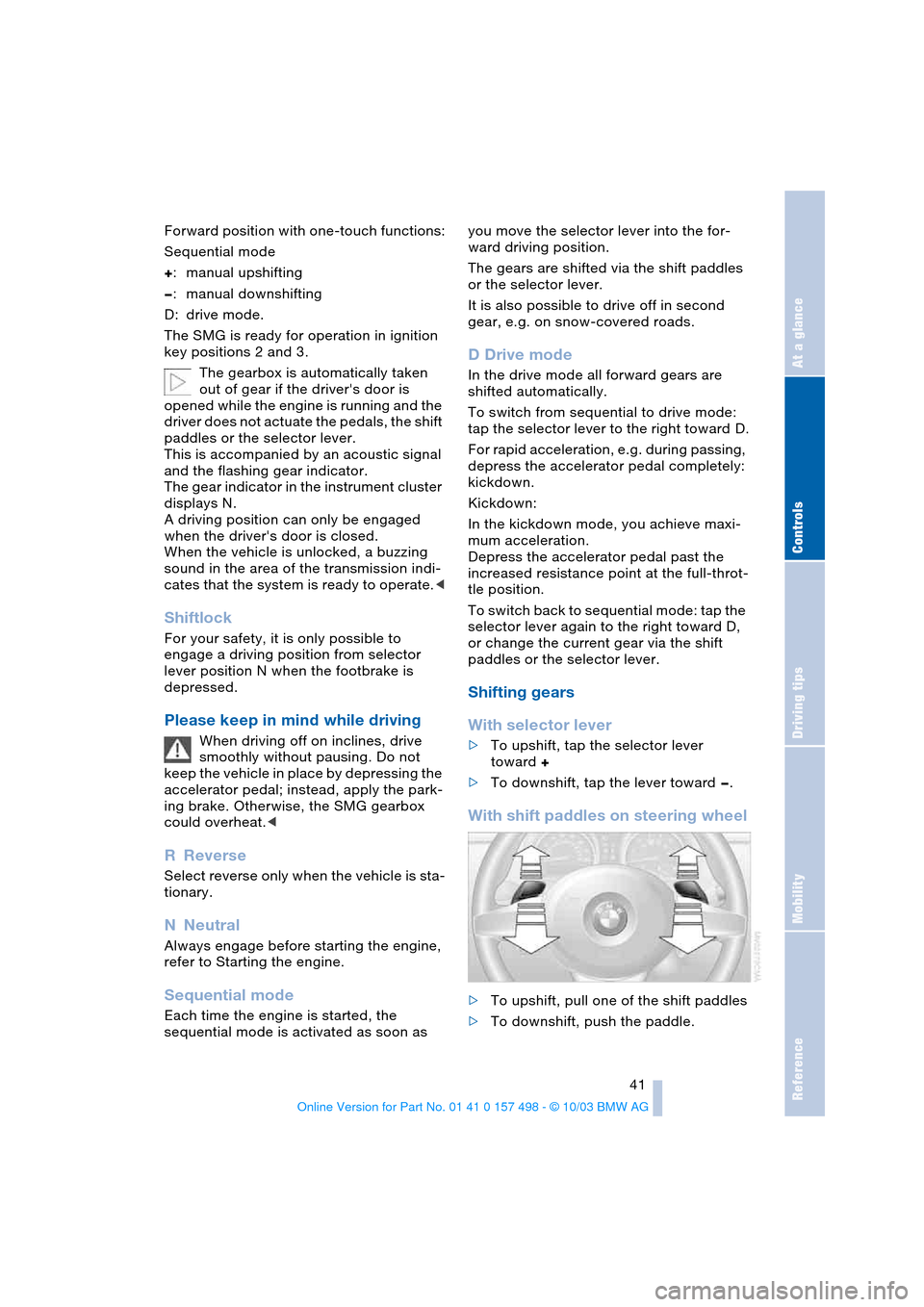
With shift paddles on steering wheel
>To upshift, pull one of the shift paddles
>To downshift, push the paddle.
Page 45 of 120

Reference
At a glance
Controls
Driving tips
Mobility
43
Deactivating the Sport program
Press the SPORT button again.
The LED in the button goes out.
Acceleration assistant with SMG
The acceleration assistant permits opti-
mum racing-style acceleration on skid-
resistant roads.
Do not use the acceleration assistant
too often, as this could cause the
vehicle's parts to wear prematurely.<
1.Activate the Sport program
2.Press and hold the DSC button for more
than three seconds, refer to page 53
3.Depress the accelerator all the way
down rapidly: kickdown. The optimum
rpm for driving off will be adjusted.
To maintain vehicle stability, drive
with the DSC switched on whenever
possible.<
Electric Power Steering
EPS
The concept
The electric power steering is a direct,
sporting steering system that is speed-sen-
sitive.
Power support is reduced with an increase
in driving speed.
Indicator lamp
The indicator lamp stays lit:
The system has malfunctioned or is
faulty.
Please have the system inspected by the
nearest BMW center.
Steering remains operational.
Turn signal indicators/
Headlamp flasher
1High beams: blue indicator lamp
2Headlamp flasher: blue indicator lamp
3Turn signal indicator: green indicator
lamps accompanied by a periodic click-
ing sound from the relay
If the flashing of the indicator lamp
and the clicking from the relay are
both faster than normal, one of the turn
signal indicators has failed.<
To signal briefly
Press the lever up to the detent but not
beyond. It then returns to the center posi-
tion when released.
Washer/wiper system and
rain sensor*
0Wipers retracted
1Intermittent operation or rain sensor
2Normal wiper speed
3Fast wiper speed
4Brief wipe
Page 52 of 120
Everything under control
50 4.Press button 1 repeatedly until the
required minutes are set
5.Press button 2 to confirm the settings.
The set time of day is transferred to the car
radio display or appears in the instrument
cluster display.
Display mode
In ignition key position 0:
Press button 1.
The time of day is displayed for several
seconds.
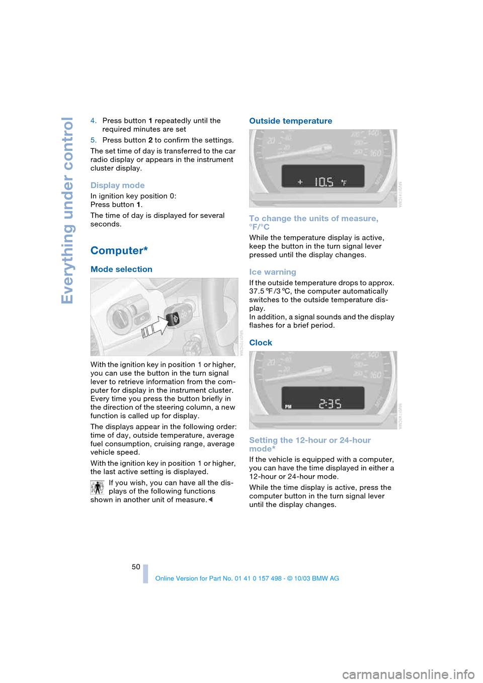
Computer*
Mode selection
With the ignition key in position 1 or higher,
you can use the button in the turn signal
lever to retrieve information from the com-
puter for display in the instrument cluster.
Every time you press the button briefly in
the direction of the steering column, a new
function is called up for display.
The displays appear in the following order:
time of day, outside temperature, average
fuel consumption, cruising range, average
vehicle speed.
With the ignition key in position 1 or higher,
the last active setting is displayed.
If you wish, you can have all the dis-
plays of the following functions
shown in another unit of measure.<
Outside temperature
To change the units of measure,
°F/°C
While the temperature display is active,
keep the button in the turn signal lever
pressed until the display changes.
Ice warning
If the outside temperature drops to approx.
37.57/36, the computer automatically
switches to the outside temperature dis-
play.
In addition, a signal sounds and the display
flashes for a brief period.
Clock
Setting the 12-hour or 24-hour
mode*
If the vehicle is equipped with a computer,
you can have the time displayed in either a
12-hour or 24-hour mode.
While the time display is active, press the
computer button in the turn signal lever
until the display changes.
Page 54 of 120

Technology for safety and driving convenience
52
Technology for safety and driving
convenience
Dynamic Stability Control
DSC
The concept
This system optimizes driving stability and
traction, especially when just starting off,
when accelerating or when cornering. It
also maintains vehicle stability, even in crit-
ical driving situations.
DSC recognizes unstable vehicle condi-
tions, such as understeering or oversteer-
ing, and, within physically feasible limits,
helps keeping the vehicle on a steady
course by reducing engine speed and by
brake applications at individual wheels.
The DSC is operational every time you start
the engine. It includes the following func-
tions:
>Automatic Stability Control plus Trac-
tion ASC+T
>Dynamic Traction Control DTC
>Dynamic Brake Control DBC
The laws of physics cannot be
repealed even with DSC. It will always
be the driver's responsibility to drive in a
manner that matches road conditions. We
therefore urge you to avoid using the addi-
tional safety margin of the system as an
excuse for taking risks.
Do not make any modifications to the DSC
system. Allow only authorized technicians
to perform service procedures on the
DSC.<
Indicator lamps
The indicator lamps in the instrument clus-
ter go out shortly after you switch on the
ignition.
Dynamic Stability Control DSC indi-
cator lamp flashes:
The system is active and governs
drive torque and braking forces.The indicator lamp stays lit:
Dynamic Stability Control DSC and
Dynamic Traction Control DTC have been
switched off via the button.
Dynamic Traction Control DTC indi-
cator lamp lights up permanently:
DTC has been deactivated via the
DSC button.
Dynamic Stability Control DSC indi-
cator lamp flashes:
Dynamic Traction Control DTC indi-
cator lamp lights up permanently:
DTC is actively regulating drive
torque and braking forces.
Interventions to increase stability are
being performed to a limited degree
only.<
The Dynamic Stability Control DSC
indicator lamp and yellow brake
warning lamp for Dynamic Brake
Control DBC light up continuously:
Dynamic Stability Control DSC,
Dynamic Traction Control DTC and
Dynamic Brake Control DBC are malfunc-
tioning.
Have the system repaired at your BMW
center.
Dynamic Stability Control DSC indi-
cator lamp and yellow brake warn-
ing lamp for Dynamic Brake Control
DBC for Canadian models:
The vehicle remains completely oper-
ational without the DSC, DTC and
DBC functions.<
In the event of a malfunction, please see
your BMW center.
Page 57 of 120
Reference
At a glance
Controls
Driving tips
Mobility
55
place in all four tires over an extended
period of time.<
On the other hand, the following situations
can lead to false warning, a delayed detec-
tion of pressure loss and even to the sys-
tem not functioning:
>Driving on snow-covered or slippery
roads
>Performance-oriented driving: slip at
the drive wheels, high levels of lateral
acceleration
>When driving with snow chains, false
warnings and undetected pressure
losses may occur
>If the Flat Tire Monitor was not initial-
ized after the last time the tire inflation
pressures were corrected, undetected
losses in pressure or false warnings
that indicate a non-existent flat tire are
possible.
Initializing the system
Each time you correct the pressure in
a tire, or change a wheel or tire, reini-
tialize the system immediately afterwards.
This requires driving.<
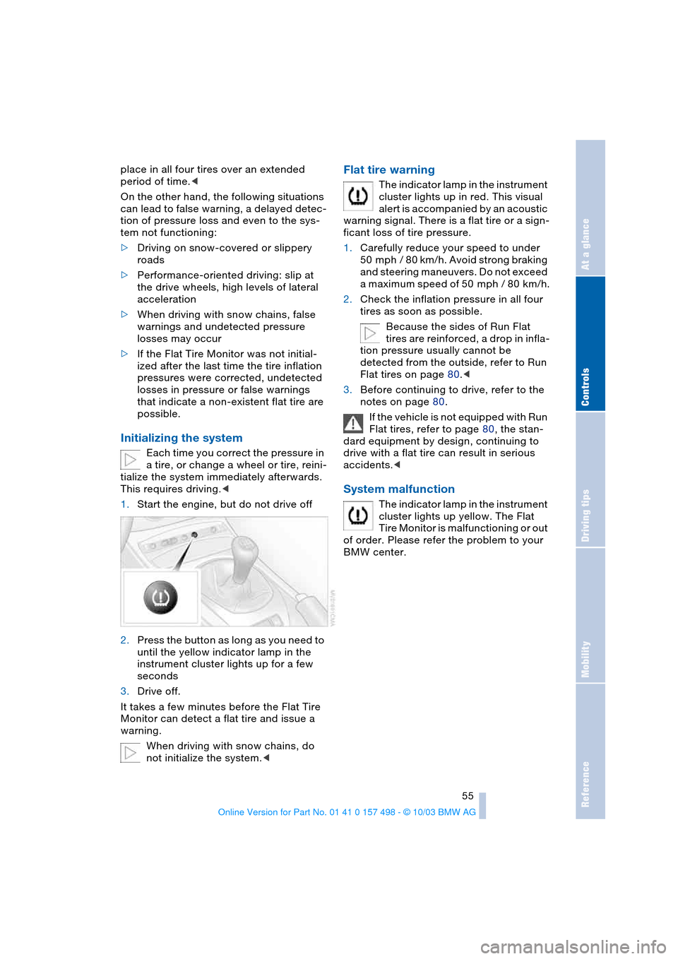
1.Start the engine, but do not drive off
2.Press the button as long as you need to
until the yellow indicator lamp in the
instrument cluster lights up for a few
seconds
3.Drive off.
It takes a few minutes before the Flat Tire
Monitor can detect a flat tire and issue a
warning.
When driving with snow chains, do
not initialize the system.<
Flat tire warning
The indicator lamp in the instrument
cluster lights up in red. This visual
alert is accompanied by an acoustic
warning signal. There is a flat tire or a sign-
ficant loss of tire pressure.
1.Carefully reduce your speed to under
50 mph / 80 km/h. Avoid strong braking
and steering maneuvers. Do not exceed
a maximum speed of 50 mph / 80 km/h.
2.Check the inflation pressure in all four
tires as soon as possible.
Because the sides of Run Flat
tires are reinforced, a drop in infla-
tion pressure usually cannot be
detected from the outside, refer to Run
Flat tires on page 80.<
3.Before continuing to drive, refer to the
notes on page 80.
If the vehicle is not equipped with Run
Flat tires, refer to page 80, the stan-
dard equipment by design, continuing to
drive with a flat tire can result in serious
accidents.<
System malfunction
The indicator lamp in the instrument
cluster lights up yellow. The Flat
Tire Monitor is malfunctioning or out
of order. Please refer the problem to your
BMW center.
Page 58 of 120
Technology for safety and driving convenience
56
Airbags
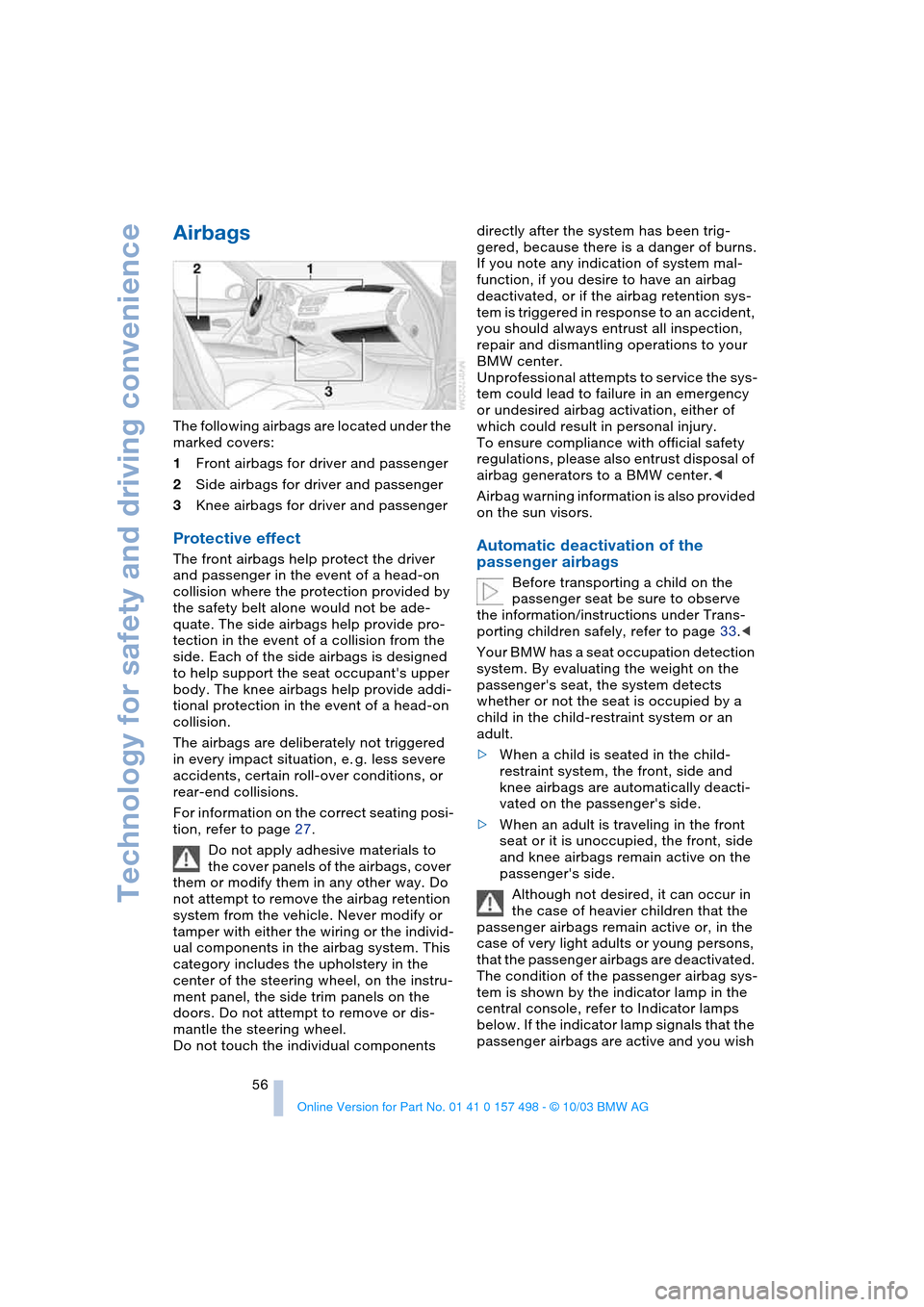
The following airbags are located under the
marked covers:
1Front airbags for driver and passenger
2Side airbags for driver and passenger
3Knee airbags for driver and passenger
Protective effect
The front airbags help protect the driver
and passenger in the event of a head-on
collision where the protection provided by
the safety belt alone would not be ade-
quate. The side airbags help provide pro-
tection in the event of a collision from the
side. Each of the side airbags is designed
to help support the seat occupant's upper
body. The knee airbags help provide addi-
tional protection in the event of a head-on
collision.
The airbags are deliberately not triggered
in every impact situation, e. g. less severe
accidents, certain roll-over conditions, or
rear-end collisions.
For information on the correct seating posi-
tion, refer to page 27.
Do not apply adhesive materials to
the cover panels of the airbags, cover
them or modify them in any other way. Do
not attempt to remove the airbag retention
system from the vehicle. Never modify or
tamper with either the wiring or the individ-
ual components in the airbag system. This
category includes the upholstery in the
center of the steering wheel, on the instru-
ment panel, the side trim panels on the
doors. Do not attempt to remove or dis-
mantle the steering wheel.
Do not touch the individual components directly after the system has been trig-
gered, because there is a danger of burns.
If you note any indication of system mal-
function, if you desire to have an airbag
deactivated, or if the airbag retention sys-
tem is triggered in response to an accident,
you should always entrust all inspection,
repair and dismantling operations to your
BMW center.
Unprofessional attempts to service the sys-
tem could lead to failure in an emergency
or undesired airbag activation, either of
which could result in personal injury.
To ensure compliance with official safety
regulations, please also entrust disposal of
airbag generators to a BMW center.<
Airbag warning information is also provided
on the sun visors.Automatic deactivation of the
passenger airbags
Before transporting a child on the
passenger seat be sure to observe
the information/instructions under Trans-
porting children safely, refer to page 33.<
Your BMW has a seat occupation detection
system. By evaluating the weight on the
passenger's seat, the system detects
whether or not the seat is occupied by a
child in the child-restraint system or an
adult.
>When a child is seated in the child-
restraint system, the front, side and
knee airbags are automatically deacti-
vated on the passenger's side.
>When an adult is traveling in the front
seat or it is unoccupied, the front, side
and knee airbags remain active on the
passenger's side.
Although not desired, it can occur in
the case of heavier children that the
passenger airbags remain active or, in the
case of very light adults or young persons,
that the passenger airbags are deactivated.
The condition of the passenger airbag sys-
tem is shown by the indicator lamp in the
central console, refer to Indicator lamps
below. If the indicator lamp signals that the
passenger airbags are active and you wish
Page 67 of 120
Reference
At a glance
Controls
Driving tips
Mobility
65
Beverage holder
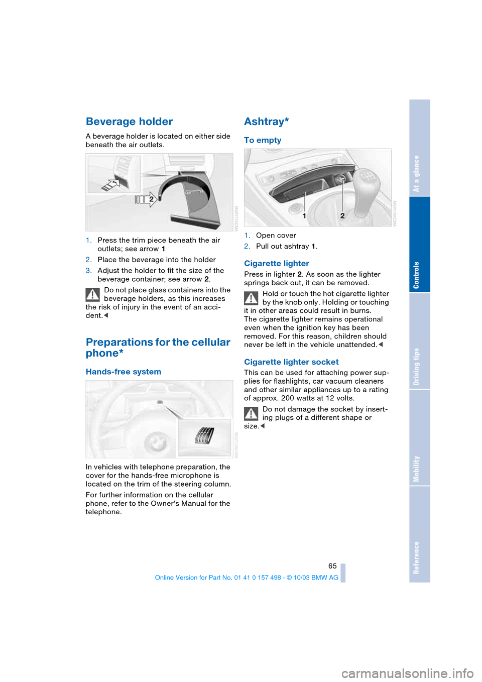
A beverage holder is located on either side
beneath the air outlets.
1.Press the trim piece beneath the air
outlets; see arrow 1
2.Place the beverage into the holder
3.Adjust the holder to fit the size of the
beverage container; see arrow 2.
Do not place glass containers into the
beverage holders, as this increases
the risk of injury in the event of an acci-
dent.<
Preparations for the cellular
phone*
Hands-free system
In vehicles with telephone preparation, the
cover for the hands-free microphone is
located on the trim of the steering column.
For further information on the cellular
phone, refer to the Owner's Manual for the
telephone.
Ashtray*
To empty
1.Open cover
2.Pull out ashtray 1.
Cigarette lighter
Press in lighter 2. As soon as the lighter
springs back out, it can be removed.
Hold or touch the hot cigarette lighter
by the knob only. Holding or touching
it in other areas could result in burns.
The cigarette lighter remains operational
even when the ignition key has been
removed. For this reason, children should
never be left in the vehicle unattended.<
Cigarette lighter socket
This can be used for attaching power sup-
plies for flashlights, car vacuum cleaners
and other similar appliances up to a rating
of approx. 200 watts at 12 volts.
Do not damage the socket by insert-
ing plugs of a different shape or
size.<
Page 72 of 120
Special operating instructions
70 Do not coast with the clutch
depressed or with the transmission or
selector lever in Neutral. Do not coast with
the engine switched off. Otherwise the
engine provides no braking effect and there
is no power-assist for braking or steering
when the engine is off.<
Brake pads
The yellow indicator lamp for the
brake pads lights up:
Have the condition of the brake
pads inspected.
For your own safety: use brake pads
which the manufacturer has approved
for your specific vehicle model. The manu-
facturer cannot evaluate non-approved
brake pads to determine if they are suitable
for use, and therefore cannot ensure the
operating safety of the vehicle in the event
of their use.<
Cargo loading
Avoid overloading the vehicle so that
the permitted load on the tires is not
exceeded. Otherwise, overheating and
inner damage to the tires may result. The
ultimate result can assume the form of a
sudden air loss.<
Determining the maximum load
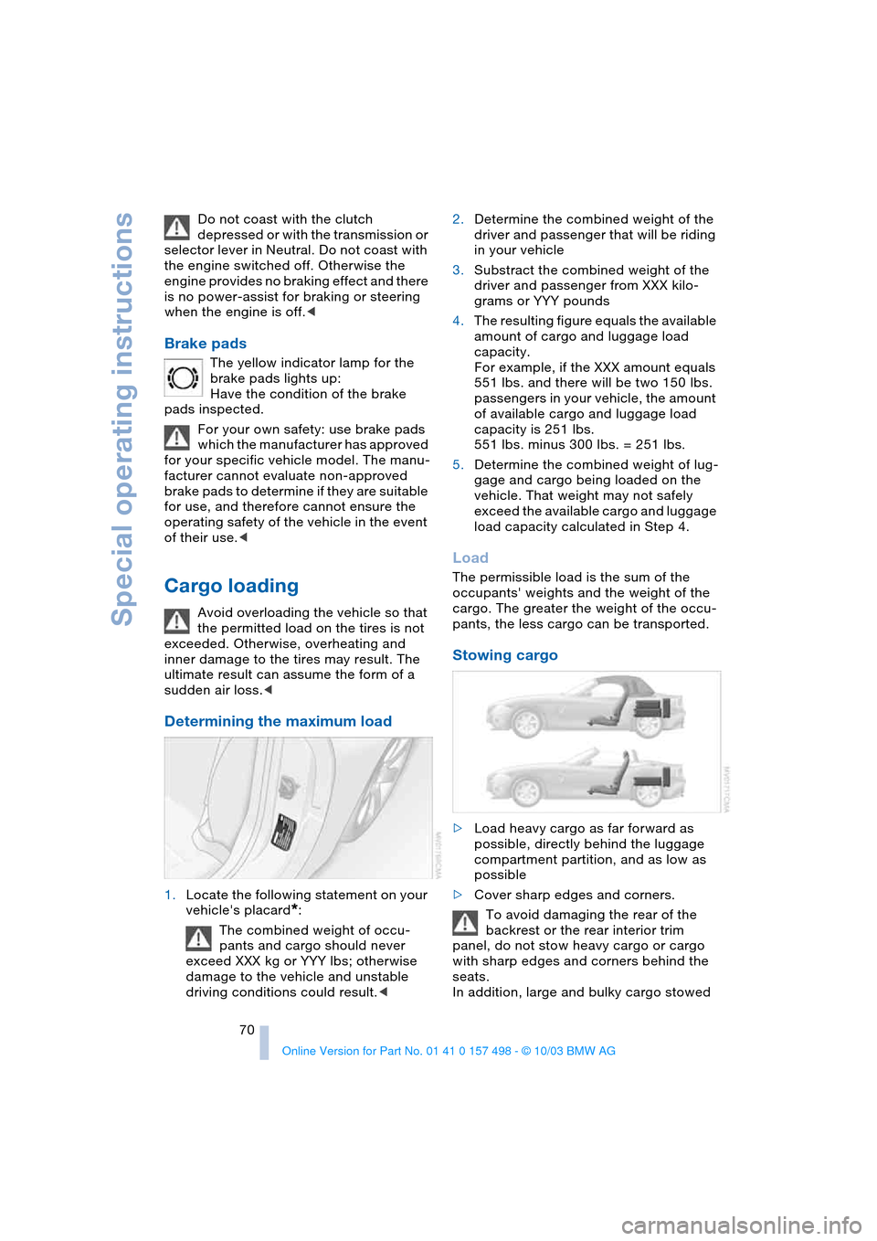
1.Locate the following statement on your
vehicle's placard
*:
The combined weight of occu-
pants and cargo should never
exceed XXX kg or YYY lbs; otherwise
damage to the vehicle and unstable
driving conditions could result.<2.Determine the combined weight of the
driver and passenger that will be riding
in your vehicle
3.Substract the combined weight of the
driver and passenger from XXX kilo-
grams or YYY pounds
4.The resulting figure equals the available
amount of cargo and luggage load
capacity.
For example, if the XXX amount equals
551 lbs. and there will be two 150 lbs.
passengers in your vehicle, the amount
of available cargo and luggage load
capacity is 251 lbs.
551 lbs. minus 300 lbs. = 251 lbs.
5.Determine the combined weight of lug-
gage and cargo being loaded on the
vehicle. That weight may not safely
exceed the available cargo and luggage
load capacity calculated in Step 4.
Load
The permissible load is the sum of the
occupants' weights and the weight of the
cargo. The greater the weight of the occu-
pants, the less cargo can be transported.
Stowing cargo
>Load heavy cargo as far forward as
possible, directly behind the luggage
compartment partition, and as low as
possible
>Cover sharp edges and corners.
To avoid damaging the rear of the
backrest or the rear interior trim
panel, do not stow heavy cargo or cargo
with sharp edges and corners behind the
seats.
In addition, large and bulky cargo stowed