Page 9 of 48
9
M54engMS43/ST036/6/20000
SYSTEM OVERVIEW I-P-O
Service
Engine
Soon
ART-IPO46X.EPS
Page 28 of 48

28
M54engMS43/ST036/6/2000
MISFIRE DETECTION
As part of the CARB/OBD regulations the engine control module must determine if misfire
is occurring and also identify the specific cylinder(s) and the severity of the misfire event,
and whether it is emissions relevant or catalyst damaging. In order to accomplish these
tasks the control module monitors the crankshaft for acceleration losses during firing seg-
ments of each cylinder based on firing order.
Misfire Detection Example: M54 (6 Cyl.) with Siemens System
The misfire/engine roughness calculation is derived from the differences in the period dura-
tion (T) of individual increment gear segments. Each segment period consist of an angular
range of 120° crank angle that starts 78° before Top Dead Center (TDC).
If the expected period duration is greater than the permissible value a misfire fault for the
particular cylinder is stored in the fault memory of the ECM. Depending on the level of mis-
fire rate measured the control unit will illuminate the "Service Engine Soon" light, may cut-
off fuel to the particular cylinder and may switch lambda operation to open-loop. All mis-
fire faults are weighted to determine if the misfire is emissions relevant or catalyst damag-
ing.
_________________________________________________________________
_________________________________________________________________
_________________________________________________________________
_________________________________________________________________
_________________________________________________________________
_________________________________________________________________
_________________________________________________________________
_________________________________________________________________
_________________________________________________________________
Page 29 of 48

29
M54engMS43/ST036/6/20000
EMISSIONS RELEVANT:
During an interval of 1000 crankshaft revolutions
the misfire events of all cylinders are
added and if the sum is greater than a predetermined value a fault will be set identifying the
particular cylinder(s). The “Service Engine Soon” light will be illuminated during and after
the second cycle if the fault is again present.
CATALYST DAMAGING:
During an interval of 200 crankshaft revolutions
the misfire events of all cylinders are added
and if the sum is greater than a predetermined value a fault will be set identifying the par-
ticular cylinders(s). The “Service Engine Soon” lamp:
• On vehicles with a Siemens Control Module (M54 engines) - the lamp will immediately go
to a steady illumination since fuel to the injector(s) is removed. Fuel cut-off to the cylin-
der will resume after several (
>>7) periods of decel if crankshaft sensor adaptation is suc-
cessfully completed or the engine is shut-off and restarted.
In each case the number of misfire events permitted is dependent on engine speed, load
and temperature map.
The process of misfire detection continues well after the diagnostic drive cycle requirements
have been completed. Misfire detection is an on-going monitoring process
that is only dis-
continued under certain conditions.
Misfire detection is only disabled under the following conditions:
___________________________________________________________________
___________________________________________________________________
___________________________________________________________________
REQUIREMENTSSTATUS/CONDITION
Engine Speed< 512 RPM
Engine LoadVarying/Unstable
Throttle AngleVarying/Unstable
TimingTiming retard request active (i.e. knock
control - ASC, AGS)
Engine Start-upUp to 5 seconds after start-up
A/CUp to 0.5 seconds after A/C activation
Decel fuel cut-offActive
Rough road recognitionActive
ASC ControlActive
Page 38 of 48

38
M54engMS43/ST036/6/2000
The Secondary Air Injection System is monitored via the use of the pre-catalyst oxygen sen-
sor(s). Once the air pump is active and is air injected into the system the signal at the oxy-
gen sensor will reflect a lean condition. If the oxygen sensor signal does not change with-
in a predefined time a fault will be set and identify the faulty bank(s). If after completing the
next cold start and a fault is again present the "Service Engine Soon" light will be illuminat-
ed.
Example: Secondary Air Injection Monitoring (M54-Siemens System)
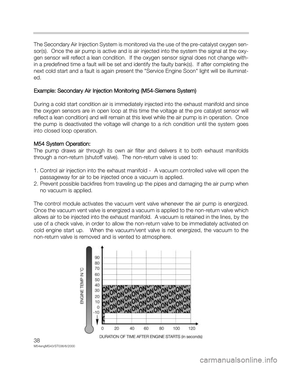
During a cold start condition air is immediately injected into the exhaust manifold and since
the oxygen sensors are in open loop at this time the voltage at the pre catalyst sensor will
reflect a lean condition) and will remain at this level while the air pump is in operation. Once
the pump is deactivated the voltage will change to a rich condition until the system goes
into closed loop operation.
M54 System Operation:
The pump draws air through its own air filter and delivers it to both exhaust manifolds
through a non-return (shutoff valve). The non-return valve is used to:
1. Control air injection into the exhaust manifold - A vacuum controlled valve will open the
passageway for air to be injected once a vacuum is applied.
2. Prevent possible backfires from traveling up the pipes and damaging the air pump when
no vacuum is applied.
The control module activates the vacuum vent valve whenever the air pump is energized.
Once the vacuum vent valve is energized a vacuum is applied to the non-return valve which
allows air to be injected into the exhaust manifold. A vacuum is retained in the lines, by the
use of a check valve, in order to allow the non-return valve to be immediately activated on
cold engine start up. When the vacuum/vent valve is not energized, the vacuum to the
non-return valve is removed and is vented to atmosphere.
Page 40 of 48
40
M54engMS43/ST036/6/2000
RZV IGNITION SYSTEM
The Siemens MS43.0 system uses a multiple spark ignition function. The purpose of mul-
tiple ignition is:
• Provide clean burning during engine start up and while idling (reducing emissions).
• This function helps to keep the spark plugs clean for longer service life (new BMW
longlife plugs).
Multiple ignition is active up to an engine speed of approximately 1350 RPM (varied with
engine temperature) and up to 20 degrees after TDC.
Multiple ignition is dependent on battery voltage. When the voltage is low, the primary cur-
rent is also lower and a longer period of time is required to build up the magnetic field in the
coil(s).
• Low battery voltage = less multiple ignitions
• High battery voltage = more multiple ignitions
The 240 ohm shunt resistor is still used on the MS43.0 system for detecting secondary igni-
tion faults and diagnostic purposes.
MS 43.0