Page 101 of 130

PERIODIC MAINTENANCE AND MINOR REPAIR
6-44
6
NOTE:_ To install the quick fastener, push the
center pin out so that it will protrude
from the fastener head, insert the fas-
tener into the auxiliary light bulb cover,
and then push the protruding pin in until
it is flush with the fastener head. _
EAU03730
Tail/brake light This motorcycle is equipped with an
LED type of tail/brake light.
If the tail/brake light does not come on,
have a Yamaha dealer check it.
EAU03497
Replacing a turn signal light
bulb 1. Remove the turn signal light lens
by removing the screw.
2. Remove the defective bulb by
pushing it in and turning it
counterclockwise.
3. Insert a new bulb into the socket,
push it in, and then turn it clock-
wise until it stops.
4. Install the lens by installing the
screw.
ECA00065
CAUTION:@ Do not overtighten the screw, other-
wise the lens may break. @
1. Quick fastener
2. Pin
After removal
Before installation
1. Screw
U5SLE0.book Page 44 Wednesday, September 11, 2002 11:46 AM
Page 102 of 130

PERIODIC MAINTENANCE AND MINOR REPAIR
6-45
6
EAU04574
Replacing the license plate
light bulb 1. Remove the license plate light unit
by removing the screws.2. Remove the socket (together with
the bulb) by pulling it out.
3. Remove the defective bulb by pull-
ing it out.
4. Insert a new bulb into the socket.
5. Install the socket (together with
the bulb) by pushing it in.
6. Install the license plate light unit by
installing the screws.
EAU01579
Supporting the motorcycle Since this model is not equipped with a
centerstand, follow these precautions
when removing the front and rear
wheel or performing other mainte-
nance requiring the motorcycle to
stand upright. Check that the motor-
cycle is in a stable and level position
before starting any maintenance. A
strong wooden box can be placed un-
der the engine for added stability.
To service the front wheel
1. Stabilize the rear of the motorcycle
by using a motorcycle stand or, if
an additional motorcycle stand is
not available, by placing a jack un-
der the frame in front of the rear
wheel.
2. Raise the front wheel off the
ground by using a motorcycle
stand.
1. Screw (× 2)
1. License plate light bulb
2. License plate light unit
U5SLE0.book Page 45 Wednesday, September 11, 2002 11:46 AM
Page 103 of 130
PERIODIC MAINTENANCE AND MINOR REPAIR
6-46
6 To service the rear wheel
Raise the rear wheel off the ground by
using a motorcycle stand or, if a motor-
cycle stand is not available, by placing
a jack either under each side of the
frame in front of the rear wheel or under
each side of the swingarm.
EAU04956
Front wheel To remove the front wheel
EW000122
WARNING
_ �
It is advisable to have a Yamaha
dealer service the wheel.
�
Securely support the motor-
cycle so that there is no danger
of it falling over.
_1. Loosen the axle bolt, the wheel
axle pinch bolts, and then the
brake caliper bolts.2. Lift the front wheel off the ground
according to the procedure on
page 6-45.
3. Remove the brake hose holder on
each side by removing the bolt.
4. Remove the brake caliper on each
side by removing the bolts.1. Front wheel axle pinch bolt (× 4)
1. Brake hose holder
2. Brake caliper
3. Axle bolt
4. Bolt (× 3)
U5SLE0.book Page 46 Wednesday, September 11, 2002 11:46 AM
Page 104 of 130

PERIODIC MAINTENANCE AND MINOR REPAIR
6-47
65. Remove the axle bolt, pull the
wheel axle out, and then remove
the wheel.
ECA00046
CAUTION:_ Do not apply the brake after the
brake calipers have been removed,
otherwise the brake pads will be
forced shut. _
EAU05021
To install the front wheel
1. Lift the wheel up between the fork
legs.
2. Insert the wheel axle.
3. Lower the front wheel so that it is
on the ground.
4. Install the brake calipers by install-
ing the bolts, and then tightening
them to the specified torque.NOTE:_ Make sure that there is enough space
between the brake pads before install-
ing the brake calipers onto the brake
discs. _5. Install the brake hose holders by
installing the bolts.
6. Secure the wheel axle by installing
the axle bolt, and then tightening
the wheel axle to the specified
torque.
NOTE:_ While tightening the wheel axle, hold
the axle bolt to keep it from turning. _
1. Wheel axle
Tightening torque:
Brake caliper bolt:
40 Nm (4.0 m·kgf)
Tightening torque:
Wheel axle:
91 Nm (9.1 m·kgf)
E_5sl_Periodic.fm Page 47 Thursday, October 17, 2002 1:13 PM
Page 105 of 130
PERIODIC MAINTENANCE AND MINOR REPAIR
6-48
6 7. Tighten wheel axle pinch bolt B,
and then tighten pinch bolt A to the
specified torque.
8. Retighten pinch bolt B to the spec-
ified torque.
9. Tap the outer side of the left fork
leg with a rubber mallet to align it
with the end of the wheel axle.10. Tighten wheel axle pinch bolt D,
and then tighten pinch bolt C to the
specified torque.
11. Retighten pinch bolt D to the spec-
ified torque.
12. While applying the front brake,
push down hard on the handlebar
several times to check for proper
fork operation.
1. Front wheel axle pinch bolt A
2. Front wheel axle pinch bolt B
3. Front wheel axle pinch bolt C
4. Front wheel axle pinch bolt D
Tightening torque:
Wheel axle pinch bolt:
18 Nm (1.8 m·kgf)
Tightening torque:
Wheel axle pinch bolt:
18 Nm (1.8 m·kgf)
E_5sl_Periodic.fm Page 48 Thursday, October 17, 2002 1:13 PM
Page 106 of 130
PERIODIC MAINTENANCE AND MINOR REPAIR
6-49
6
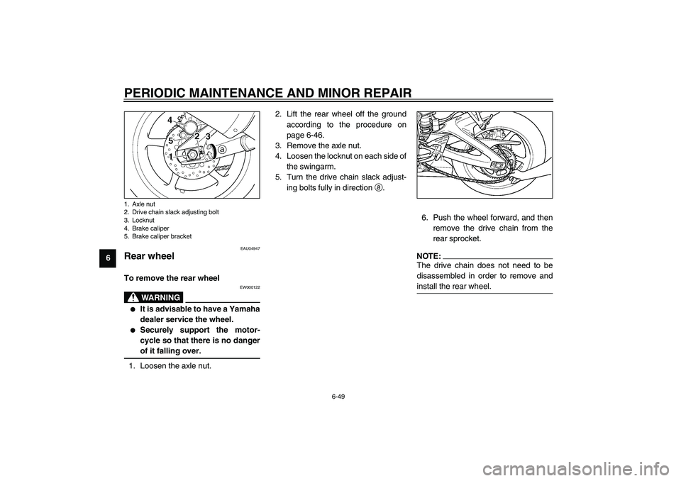
EAU04947
Rear wheel To remove the rear wheel
EW000122
WARNING
_ �
It is advisable to have a Yamaha
dealer service the wheel.
�
Securely support the motor-
cycle so that there is no danger
of it falling over.
_1. Loosen the axle nut.2. Lift the rear wheel off the ground
according to the procedure on
page 6-46.
3. Remove the axle nut.
4. Loosen the locknut on each side of
the swingarm.
5. Turn the drive chain slack adjust-
ing bolts fully in direction
a.
6. Push the wheel forward, and then
remove the drive chain from the
rear sprocket.
NOTE:_ The drive chain does not need to be
disassembled in order to remove and
install the rear wheel. _
1. Axle nut
2. Drive chain slack adjusting bolt
3. Locknut
4. Brake caliper
5. Brake caliper bracketU5SLE0.book Page 49 Wednesday, September 11, 2002 11:46 AM
Page 107 of 130

PERIODIC MAINTENANCE AND MINOR REPAIR
6-50
6 7. While supporting the brake caliper
bracket, pull the wheel axle out,
and then remove the wheel.
ECA00048
CAUTION:_ Do not apply the brake after the
wheel has been removed together
with the brake disc, otherwise the
brake pads will be forced shut. _
EAU04948
To install the rear wheel
1. Install the wheel and the brake cal-
iper bracket by inserting the wheel
axle from the left-hand side.NOTE:_ �
Be sure to insert the retainer on
the brake caliper bracket into the
slot in the swingarm.
�
Make sure that there is enough
space between the brake pads be-
fore installing the wheel.
_
2. Install the drive chain onto the rear
sprocket, and then adjust the drive
chain slack. (See page 6-33 for
drive chain slack adjustment pro-
cedures.)
3. Install the axle nut, and then lower
the rear wheel so that it is on the
ground.
4. Tighten the axle nut to the speci-
fied torque.
1. Wheel axle
1. Retainer
2. Slot
Tightening torque:
Axle nut:
110 Nm (11.0 m·kgf)
U5SLE0.book Page 50 Wednesday, September 11, 2002 11:46 AM
Page 108 of 130
PERIODIC MAINTENANCE AND MINOR REPAIR
6-51
6
EAU03087
Troubleshooting Although Yamaha motorcycles receive
a thorough inspection before shipment
from the factory, trouble may occur dur-
ing operation. Any problem in the fuel,
compression, or ignition systems, for
example, can cause poor starting and
loss of power.
The following troubleshooting charts
represent quick and easy procedures
for checking these vital systems your-
self. However, should your motorcycle
require any repair, take it to a Yamaha
dealer, whose skilled technicians have
the necessary tools, experience, and
know-how to service the motorcycle
properly.
Use only genuine Yamaha replace-
ment parts. Imitation parts may look
like Yamaha parts, but they are often
inferior, have a shorter service life and
can lead to expensive repair bills. U5SLE0.book Page 51 Wednesday, September 11, 2002 11:46 AM