Page 136 of 506
3 - 8
INSP
ADJRADIATOR CAP OPENING PRESSURE INSPECTION/
COOLING SYSTEM INSPECTION
RADIATOR CAP OPENING PRESSURE
INSPECTION
1. Attach:
�Radiator cap tester 1
�Radiator cap tester adapter 2
NOTE:
Apply water on the radiator cap seal.
3Radiator cap
2. Apply the specified pressure.
3. Inspect:
�Pressure
Impossible to maintain the specified pres-
sure for 10 seconds → Replace.
Radiator cap tester:
YU-24460-01/90890-01325
Radiator cap tester adapter:
YU-33984/90890-01352
Radiator cap opening pressure:
95 ~ 125 kPa (0.95 ~ 1.25 kg/cm2,
13.5 ~ 17.8 psi)
5PA30060
COOLING SYSTEM INSPECTION
1. Inspect:
�Coolant level
2. Attach:
�Radiator cap tester 1
�Radiator cap tester adapter 2
3. Apply the specified pressure.
Radiator cap tester:
YU-24460-01/90890-01325
Radiator cap tester adapter:
YU-33984/90890-01352
Standard pressure:
180 kPa (1.8 kg/cm2, 25.6 psi)
5PA30070
Page 138 of 506
3 - 9
INSP
ADJ
CLUTCH ADJUSTMENT
CAUTION:
�Do not apply pressure more than speci-
fied pressure.
�Radiator should be filled fully.
4. Inspect:
�Pressure
Impossible to maintain the specified pres-
sure for 10 seconds → Repair.
�Radiator 1
�Radiator hose joint 2
Coolant leakage → Repair or replace.
�Radiator hose 3
Swelling → Replace.
5PA30080
CLUTCH ADJUSTMENT
1. Check:
�Clutch lever free play a
Out of specification → Adjust.
Clutch lever free play
a:
10 ~ 15 mm (0.39 ~ 0.59 in)
5PA30090
2. Adjust:
�Clutch lever free play
NOTE:
�Make minute adjustment on the lever side.
�After adjustment, check proper operation of
clutch lever. Clutch lever free play adjustment steps:
�Loosen the locknut 1.
�Turn the adjuster 2 until free play a is
within the specified limits.
�Tighten the locknut.
5PA30100
Page 202 of 506
4 - 3
ENGRADIATOR
EC450001
RADIATOR
5PA40030
Extent of removal:
1 Radiator removal
Extent of removal Order Part name Q’ty Remarks
RADIATOR REMOVAL
Preparation for removal Drain the coolant. Refer to “COOLANT REPLACEMENT”
section in the CHAPTER 3.
Air scoop Refer to “SEAT, FUEL TANK AND SIDE
COVERS” section.
1 Radiator guard 1
2 Radiator hose clamp 4 Only loosening.
3 Radiator hose 1 1
4 Radiator hose 2 1
5Radiator 1
6 Radiator breather hose 1
1
Page 276 of 506
4 - 40
ENG
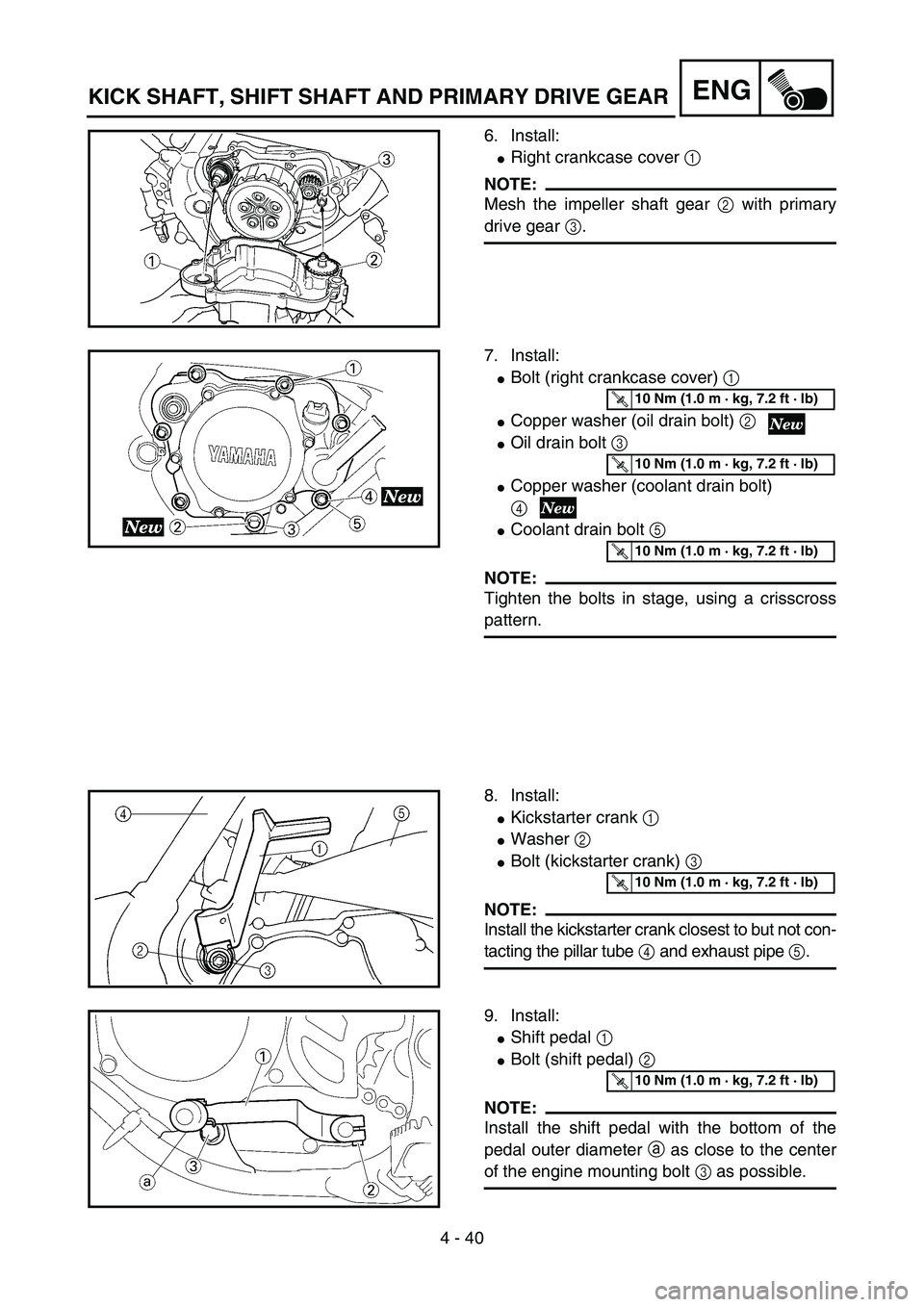
6. Install:
�Right crankcase cover 1
NOTE:
Mesh the impeller shaft gear 2 with primary
drive gear 3.
5PA41200
7. Install:
�Bolt (right crankcase cover) 1
�Copper washer (oil drain bolt) 2
�Oil drain bolt 3
�Copper washer (coolant drain bolt)
4
�Coolant drain bolt 5
NOTE:
Tighten the bolts in stage, using a crisscross
pattern.
5PA41210
T R..10 Nm (1.0 m · kg, 7.2 ft · lb)
T R..10 Nm (1.0 m · kg, 7.2 ft · lb)
T R..10 Nm (1.0 m · kg, 7.2 ft · lb)
8. Install:
�Kickstarter crank 1
�Washer 2
�Bolt (kickstarter crank) 3
NOTE:
Install the kickstarter crank closest to but not con-
tacting the pillar tube 4 and exhaust pipe 5.
5PA41220
T R..10 Nm (1.0 m · kg, 7.2 ft · lb)
9. Install:
�Shift pedal 1
�Bolt (shift pedal) 2
NOTE:
Install the shift pedal with the bottom of the
pedal outer diameter a as close to the center
of the engine mounting bolt 3 as possible.
5PA41230
T R..10 Nm (1.0 m · kg, 7.2 ft · lb)
KICK SHAFT, SHIFT SHAFT AND PRIMARY DRIVE GEAR
Page 280 of 506
4 - 42
ENG
REMOVAL POINTS
Impeller shaft
1. Remove:
�Impeller 1
�Washer 2
�Impeller shaft 3
NOTE:
Hold the impeller shaft on its width across the
flats a with spanners, etc. and remove the
impeller.
5PA41250
EC4G3210
Oil seal
NOTE:
�It is not necessary to disassemble the water
pump, unless there is an abnormality such
as excessive change in coolant level, discol-
oration of coolant, or milky transmission oil.
�Replace the oil seal whenever it is remov-
aled.
1. Remove:
�Bearing 1
2. Remove:
�Oil seal 1
5PA41260
5PA41270
INSPECTION
EC444200
Impeller shaft
1. Inspect:
�Impeller shaft 1
Bend/wear/damage → Replace.
Fur deposits → Clean.
5PA41280
WATER PUMP
Page 284 of 506
4 - 44
ENG
2. Install:
�Bearing 1
NOTE:
Install the bearing by pressing its outer race
parallel.
5PA41330
Impeller shaft
1. Install:
�Impeller shaft 1
�Washer 2
�Impeller 3
NOTE:
�Take care so that the oil seal lip is not dam-
aged or the spring does not slip off its posi-
tion.
�When installing the impeller shaft, apply the
lithium soap base grease on the oil seal lip
and impeller shaft. And install the shaft while
turning it.
�Hold the impeller shaft on its width across
the flats a with spanners, etc. and install the
impeller.
5PA41340
T R..14 Nm (1.4 m · kg, 10 ft · lb)
5PA41350
2. Install:
�Gasket (water pump housing) 1
5PA41360
3. Install:
�Water pump housing 1
�Bolt (water pump housing) 2
�Copper washer (coolant drain bolt)
3
�Coolant drain bolt 4
5PA41370
T R..10 Nm (1.0 m · kg, 7.2 ft · lb)
T R..10 Nm (1.0 m · kg, 7.2 ft · lb)
WATER PUMP
Page 294 of 506
4 - 49
ENG
EC4M0000
ENGINE REMOVAL
5PA41490
Extent of removal Order Part name Q’ty Remarks
ENGINE REMOVAL
Preparation for removal Hold the machine by placing the
suitable stand under the frame.
WARNING
Support the machine securely so there is no
danger of it falling over.
Drain the coolant. Refer to “COOLANT REPLACEMENT”
section in the CHAPTER 3.
Seat and fuel tank Refer to “SEAT, FUEL TANK AND SIDE
COVERS” section.
Carburetor Refer to “CARBURETOR AND REED
VALVE” section.
Exhaust pipe and silencer Refer to “EXHAUST PIPE AND
SILENCER” section.
Clutch cable Disconnect at engine side.
Radiator hose 1 Disconnect at cylinder head side.
Radiator hose 2 Disconnect at water pump side.
Spark plug cap
Disconnect the CDI magneto
lead.
ENGINE REMOVAL


 4 - 3
ENGRADIATOR
EC450001
RADIATOR
5PA40030
Extent of removal:
1 Radiator removal
Extent of removal Order Part name Q’ty Remarks
RADIATOR REMOVAL
Preparation for removal Drain the coolant. Refer to")


 4 - 49
ENG
EC4M0000
ENGINE REMOVAL
5PA41490
Extent of removal Order Part name Q’ty Remarks
ENGINE REMOVAL
Preparation for removal Hold the machine by placing the
suitable stand under the frame.
WAR")