Page 390 of 644
4 - 73
ENGKICK AXLE AND SHIFT SHAFT
EC4B5111
Stopper lever
1. Install:
�Torsion spring 1
�Stopper lever 2
�Bolt (stopper lever) 3
NOTE:
Align the stopper lever roller with the slot on
segment.
Shift guide and shift lever assembly
1. Install:
�Spring 1
�Pawl pin 2
�Pawl 3
To shift lever 4.
NOTE:
Apply the engine oil on the springs, pawl pins
and pawls.
2. Install:
�Shift lever assembly 1
To shift guide 2.
T R..10 Nm (1.0 m · kg, 7.2 ft · lb)
2
1
3. Install:
�Shift lever assembly 1
�Shift guide 2
NOTE:
�The shift lever assembly is installed at the
same time as the shift guide.
�Apply the engine oil on the bolt (segment)
shaft.
4. Install:
�Bolt (shift guide) 1
T R..10 Nm (1.0 m · kg, 7.2 ft · lb)
Page 392 of 644
4 - 74
ENGKICK AXLE AND SHIFT SHAFT
EC4C5301
Shift shaft
1. Install:
�Roller 1
�Collar 2
�Torsion spring 3
�Shift shaft 4
NOTE:
Apply the engine oil on the roller and shift
shaft.
2. Install:
�Shift pedal 1
�Bolt (shift pedal)
NOTE:
When installing the shift pedal onto the shift shaft,
be sure that the center of the shift pedal is about
2 mm (0.08 in) a above the top of the footrest.
T R..12 Nm (1.2 m · kg, 8.7 ft · lb)
Kick axle assembly
1. Install:
�Kick gear 1
�Plain washer 2
�Circlip 3
�Ratchet wheel 4
�Spring 5
�Plain washer 6
�Circlip 7
To kick axle 8.
NOTE:
�Apply the molybdenum disulfide oil on the
inner circumferences of the kick gear and
ratchet wheel.
�Align the punch mark a on the ratchet wheel
with the punch mark b on the kick axle.
New
New
2. Install:
�Torsion spring 1
To kick axle 2.
NOTE:
Make sure the stopper a of the torsion spring
fits into the hole b on the kick axle.
Page 394 of 644
4 - 75
ENGKICK AXLE AND SHIFT SHAFT
3. Install:
�Spring guide 1
NOTE:
Slide the spring guide into the kick axle, make
sure the groove a in the spring guide fits on
the stopper of the torsion spring.
4. Install:
�Kick axle assembly 1
�Plain washer 2
NOTE:
�Apply the molybdenum disulfide grease on
the contacting surfaces of the kick axle stop-
per a and stopper plate 3.
�Apply the engine oil on the kick axle.
�Slide the kick axle assembly into the crank-
case and make sure the kick axle stopper fits
into the stopper plate.
5. Hook:
�Torsion spring 1
NOTE:
Turn the torsion spring clockwise and hook
into the proper hole a in the crankcase.
Kick idle gear
1. Install:
�Kick idle gear 1
�Plain washer 2
�Circlip 3
NOTE:
�Install the kick idle gear with its depressed
side a toward you.
�Apply the engine oil on the kick idle gear
inner circumference.
New
Page 404 of 644
4 - 80
ENGENGINE REMOVAL
EC4M0000
ENGINE REMOVAL
Extent of removal Order Part name Q’ty Remarks
ENGINE REMOVAL
Preparation for removal Hold the machine by placing the
suitable stand under the frame.
WARNING
Support the machine securely so there is no
danger of it falling over.
Seat and fuel tank Refer to “SEAT, FUEL TANK AND SIDE
COVERS” section.
Carburetor Refer to “CARBURETOR” section.
Exhaust pipe and silencer Refer to “EXHAUST PIPE AND
SILENCER” section.
Clutch cable and guide Disconnect at engine side.
Radiator Refer to “RADIATOR” section.
Shift pedal Refer to “CDI MAGNETO” section.
Cylinder head breather hose and
oil tank breather hoseRefer to “CAMSHAFTS” section.
Drain the engine oil Refer to “ENGINE OIL REPLACEMENT”
section in the CHAPTER 3.
Ignition coil
Disconnect the CDI magneto lead.
Page 406 of 644
4 - 81
ENGENGINE REMOVAL
Extent of removal:1 Engine removal
Extent of removal Order Part name Q’ty Remarks
1 Engine skid plate (front) 1
2 Neutral switch 1
3 Oil hose 2
4 Chain cover 1
5 Nut (drive sprocket) 1
Refer to “REMOVAL POINTS”. 6 Lock washer 1
7 Drive sprocket 1
8 Clip 1
9 Bolt (brake pedal) 1
10 Brake pedal 1
11 Engine upper bracket (right) 1
12 Engine upper bracket (left) 1
13 Engine lower bracket 2
14 Engine mounting bolt 3
15 Pivot shaft 1
Refer to “REMOVAL POINTS”.
16 Engine 1
1
Page 412 of 644
4 - 84
ENGENGINE REMOVAL
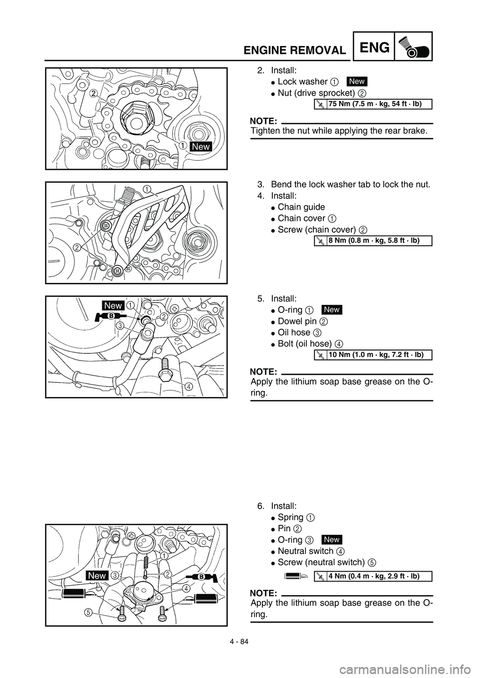
2. Install:
�Lock washer 1
�Nut (drive sprocket) 2
NOTE:
Tighten the nut while applying the rear brake.
New
T R..75 Nm (7.5 m · kg, 54 ft · lb)
3. Bend the lock washer tab to lock the nut.
4. Install:
�Chain guide
�Chain cover 1
�Screw (chain cover) 2
21T R..8 Nm (0.8 m · kg, 5.8 ft · lb)
5. Install:
�O-ring 1
�Dowel pin 2
�Oil hose 3
�Bolt (oil hose) 4
NOTE:
Apply the lithium soap base grease on the O-
ring.
6. Install:
�Spring 1
�Pin 2
�O-ring 3
�Neutral switch 4
�Screw (neutral switch) 5
NOTE:
Apply the lithium soap base grease on the O-
ring.
New
T R..10 Nm (1.0 m · kg, 7.2 ft · lb)
New
T R..4 Nm (0.4 m · kg, 2.9 ft · lb)
Page 422 of 644
4 - 89
ENGCRANKCASE AND CRANKSHAFT
Crankshaft
1. Remove:
�Crankshaft 1
Use the crankcase separating tool 2.
CAUTION:
Do not use a hammer to drive out the
crankshaft.
Crankshaft bearing
1. Remove:
�Bearing 1
NOTE:
�Remove the bearing from the crankcase by
pressing its inner race.
�Do not use the removed bearing.
Crankcase separating tool:
YU-1135-A/90890-01135
INSPECTION
Timing chain and timing chain guide
1. Inspect:
�Timing chain
Cracks/stiff → Replace the timing chain
and camshaft sprocket as a set.
2. Inspect:
�Timing chain guide
Wear/damage → Replace.
EC4N4101
Crankcase
1. Inspect:
�Contacting surface a
Scratches → Replace.
�Engine mounting boss b, crankcase
Cracks/damage → Replace.
2. Inspect:
�Bearing
Rotate inner race with a finger.
Rough spot/seizure → Replace.
3. Inspect:
�Oil seal
Wear/damage → Replace.
Page 430 of 644

To crankcase (left).
NOTE:
�Fit the crankcase (right) onto the crankcase
(left). Tap lightly on the case with")
4 - 93
ENGCRANKCASE AND CRANKSHAFT
5. Install:
�Dowel pin 1
�O-ring 2
�Crankcase (right)
To crankcase (left).
NOTE:
�Fit the crankcase (right) onto the crankcase
(left). Tap lightly on the case with soft ham-
mer.
�When installing the crankcase, the connect-
ing rod should be positioned at TDC (top
dead center).
New
6. Tighten:
�Hose guide 1
�Clutch cable holder 2
�Bolt (clutch cable holder)
�Bolt (crankcase)
NOTE:
Tighten the crankcase tightening bolts in
stage, using a crisscross pattern.
7. Install:
�Oil delivery pipe
�O-ring
�Bolt (oil delivery pipe)
8. Install:
�Timing chain
�Timing chain guide (rear)
�Bolt (timing chain guide)
9. Remove:
�Sealant
Forced out on the cylinder mating surface.
10. Apply:
�Engine oil
To the crank pin, bearing and oil deliv-
ery hole.
11. Check:
�Crankshaft and transmission operation.
Unsmooth operation → Repair.
T R..10 Nm (1.0 m · kg, 7.2 ft · lb)
T R..12 Nm (1.2 m · kg, 8.7 ft · lb)
New
T R..10 Nm (1.0 m · kg, 7.2 ft · lb)
T R..10 Nm (1.0 m · kg, 7.2 ft · lb)


 1
2 Neutral switch 1
3 Oil hose 2
4 Chain cover 1
5 Nut (drive")