Page 314 of 644
4 - 35
ENGVALVES AND VALVE SPRINGS
INSPECTION
Valve
1. Measure:
�Stem-to-guide clearance
Out of specification → Replace the
valve guide. Stem-to-guide clearance =
valve guide inside diameter a –
valve stem diameter b
Clearance (stem to guide):
Intake:
0.010 ~ 0.037 mm
(0.0004 ~ 0.0015 in)
: 0.08 mm (0.003 in)
Exhaust:
0.020 ~ 0.047 mm
(0.0008 ~ 0.0019 in)
: 0.10 mm (0.004 in)
2. Replace:
�Valve guide
Replacement steps:
NOTE:
To ease guide removal, installation and to
maintain correct fit heat the cylinder head in
an over to 100 ˚C (212 ˚F).
�Remove the valve guide using a valve
guide remover 1.
�Install the new valve guide using a valve
guide remover 1 and valve guide installer
2.
�After installing the valve guide, bore the
valve guide using a valve guide reamer 3
to obtain proper stem-to-guide clearance.
Page 330 of 644

4 - 43
ENGCYLINDER AND PISTON
REMOVAL POINTS
Piston
1. Remove:
�Piston pin clips 1
�Piston pin 2
�Piston 3
NOTE:
�Put identification marks on each piston head
for reference during reinstallation.
�Before removing each piston pin, deburr the
clip groove and pin hole area. If the piston
pin groove is deburred and the piston pin is
still difficult to remove, use the piston pin
puller 4.
CAUTION:
Do not use a hammer to drive the piston
pin out.
Piston ring
1. Remove:
�Piston rings
NOTE:
Spread the end gaps apart while at the same
time lifting the piston ring over the top of the
piston crown, as shown in the illustration.
INSPECTION
Cylinder and piston
1. Inspect:
�Cylinder and piston walls
Vertical scratches → Replace cylinder
and piston.
2. Measure:
�Piston-to-cylinder clearance
Piston pin puller:
YU-1304/90890-01304
Measurement steps:
1st step:
�Measure the cylinder bore “C” with a cylin-
der bore gauge.
NOTE:
Measure the cylinder bore “C” in parallel to
and at right angles to the crankshaft. Then,
find the average of the measurements.
Page 332 of 644
4 - 44
ENGCYLINDER AND PISTON
Cylinder bore “C”95.00 ~ 95.01 mm
(3.7402 ~ 3.7406 in)
Taper limit “T”0.05 mm (0.002 in)
Out of round “R”0.05 mm (0.002 in)
“C” = Maximum D
“T” = (Maximum D
1 or D2)
– (Maximum D
5 or D6)
“R” = (Maximum D
1, D3 or D5)
– (Minimum D2, D4 or D6)
�If out of specification, replace the cylinder,
and replace the piston and piston rings as
set.
2nd step:
�Measure the piston skirt diameter “P” with
a micrometer.
a8 mm (0.315 in) from the piston bottom edge
Piston size “P”
Standard94.945 ~ 94.960 mm
(3.738 ~ 3.739 in)
�If out of specification, replace the piston
and piston rings as a set.
3rd step:
�Calculate the piston-to-cylinder clearance
with following formula:
Piston-to-cylinder clearance =
Cylinder bore “C” –
Piston skirt diameter “P”
Piston-to-cylinder clearance:
0.040 ~ 0.065 mm
(0.0016 ~ 0.0026 in)
: 0.1 mm (0.004 in)
�If out of specification, replace the cylinder,
and replace the piston and piston rings as
set.
Page 334 of 644

4 - 45
ENGCYLINDER AND PISTON
Piston ring
1. Measure:
�Ring side clearance
Use a feeler gauge 1.
Out of specification → Replace the pis-
ton and rings as a set.
NOTE:
Clean carbon from the piston ring grooves and
rings before measuring the side clearance.
2. Position:
�Piston ring
(in cylinder)
NOTE:
Insert a ring into the cylinder and push it
approximately 10 mm (0.39 in) into the cylin-
der. Push the ring with the piston crown so that
the ring will be at a right angle to the cylinder
bore.
a10 mm (0.39 in)
Side clearance:
Standard
Top ring0.030 ~ 0.065 mm
(0.0012 ~ 0.0026 in)0.12 mm
(0.005 in)
2nd ring0.020 ~ 0.055 mm
(0.0008 ~ 0.0022 in)0.12 mm
(0.005 in)
3. Measure:
�Ring end gap
Out of specification → Replace.
NOTE:
You cannot measure the end gap on the
expander spacer of the oil control ring. If the oil
control ring rails show excessive gap, replace
all three rings.
End gap:
Standard
Top ring0.20 ~ 0.30 mm
(0.008 ~ 0.012 in)0.55 mm
(0.022 in)
2nd ring0.35 ~ 0.50 mm
(0.014 ~ 0.020 in)0.85 mm
(0.033 in)
Oil ring0.20 ~ 0.50 mm
(0.01 ~ 0.02 in)—
Page 336 of 644

4 - 46
ENGCYLINDER AND PISTON
Piston pin
1. Inspect:
�Piston pin
Blue discoloration/grooves → Replace,
then inspect the lubrication system.
2. Measure:
�Piston pin-to-piston clearance
ASSEMBLY AND INSTALLATION
Piston
1. Install:
�Piston rings
Onto the piston.
NOTE:
�Be sure to install the piston rings so that the
manufacturer’s marks or numbers are
located on the upper side of the rings.
�Lubricate the piston and piston rings liberally
with engine oil. Measurement steps:
�Measure the outside diameter (piston pin)
a.
If out of specification, replace the piston
pin.
Outside diameter (piston pin):
17.991 ~ 18.000 mm
(0.7083 ~ 0.7087 in)
�Measure the inside diameter (piston) b.
Inside diameter (piston):
18.004 ~ 18.015 mm
(0.7088 ~ 0.7093 in)
�Calculate the piston pin-to-piston clear-
ance with the following formula.
Piston pin-to-piston clearance =
Inside diameter (piston) b –
Outside diameter (piston pin) a
�If out of specification, replace the piston.
Piston pin-to-piston clearance:
0.004 ~ 0.024 mm
(0.00016 ~ 0.00094 in)
: 0.07 mm (0.003 in)
Page 378 of 644
4 - 67
ENGOIL PUMP
INSPECTION
Oil pump
1. Inspect:
�Oil pump drive gear
�Oil pump driven gear
�Rotor housing
�Oil pump cover
Cracks/wear/damage → Replace.
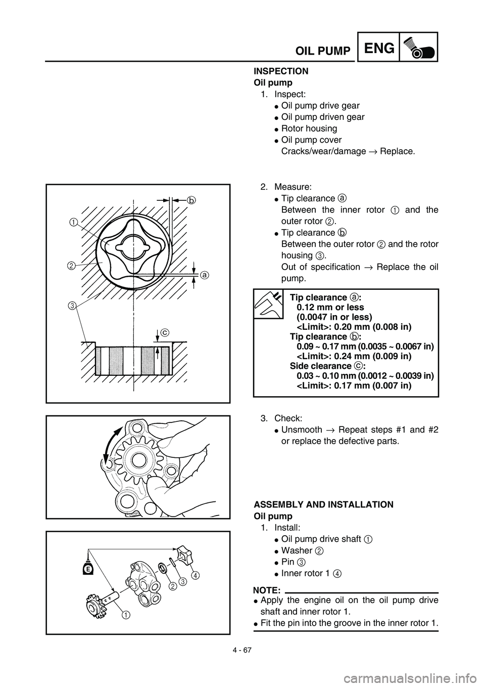
2. Measure:
�Tip clearance a
Between the inner rotor 1 and the
outer rotor 2.
�Tip clearance b
Between the outer rotor 2 and the rotor
housing 3.
Out of specification → Replace the oil
pump.
Tip clearance a:
0.12 mm or less
(0.0047 in or less)
: 0.20 mm (0.008 in)
Tip clearance b:
0.09 ~ 0.17 mm (0.0035 ~ 0.0067 in)
: 0.24 mm (0.009 in)
Side clearance c:
0.03 ~ 0.10 mm (0.0012 ~ 0.0039 in)
: 0.17 mm (0.007 in)
3. Check:
�Unsmooth → Repeat steps #1 and #2
or replace the defective parts.
ASSEMBLY AND INSTALLATION
Oil pump
1. Install:
�Oil pump drive shaft 1
�Washer 2
�Pin 3
�Inner rotor 1 4
NOTE:
�Apply the engine oil on the oil pump drive
shaft and inner rotor 1.
�Fit the pin into the groove in the inner rotor 1.
Page 424 of 644
4 - 90
ENGCRANKCASE AND CRANKSHAFT
EC4N4201
Crankshaft
1. Measure:
�Runout limit a
�Small end free play limit b
�Connecting rod big end side clearance
c
�Crank width d
Out of specification → Replace.
Use the dial gauge and a thickness
gauge.
Dial gauge and stand:
YU-3097/90890-01252
Standard
Runout
limit:0.03 mm
(0.0012 in)0.05 mm
(0.002 in)
Small end
free play:0.4 ~ 1.0 mm
(0.016 ~ 0.039 in)2.0 mm
(0.08 in)
Side
clearance:0.15 ~ 0.45 mm
(0.0059 ~ 0.0177 in)0.50 mm
(0.02 in)
Crack
width:61.95 ~ 62.00 mm
(2.439 ~ 2.441 in)—
Oil strainer
1. Inspect:
�Oil strainer
Damage → Replace.
Oil delivery pipe
1. Inspect:
�Oil delivery pipe
Cracks/damage → Replace.
�Oil delivery pipe holes 1
Clogged → Blow out with compressed
air.
Page:
< prev 1-8 9-16 17-24


Taper limit “T”0.05 mm (0.002 in)
Out of round “R”0.05 mm (0.002 in)
“C” = Maximum D
“T” = (Max")