Page 206 of 644
3 - 27
INSP
ADJ
FRONT BRAKE PAD INSPECTION AND REPLACEMENT
�Loosen the pad pin 2.
�Remove the brake hose holder 3 and cal-
iper 4 from the front fork.
�Remove the pad pin and brake pads 5.
�Connect the transparent hose 6 to the
bleed screw 7 and place the suitable con-
tainer under its end.
�Loosen the bleed screw and push the cali-
per piston in.
CAUTION:
Do not reuse the drained brake fluid.
�Tighten the bleed screw.
T R..
Bleed screw:
6 Nm (0.6 m • kg, 4.3 ft • lb)
�Install the brake pads 8 and pad pin.
NOTE:
�Install the brake pads with their projections
a into the caliper recesses b.
�Temporarily tighten the pad pin at this
point.
�Install the brake hose holder 9 and cali-
per 0 and tighten the pad pin A.
NOTE:
Fit the brake hose holder cut c over the
projection d on the front fork and clamp the
brake hose.
T R..
Bolt (caliper):
23 Nm (2.3 m • kg, 17 ft • lb)
Pad pin:
18 Nm (1.8 m • kg, 13 ft • lb)
Page 210 of 644
3 - 29
INSP
ADJ
REAR BRAKE PAD INSPECTION AND REPLACEMENT
�Remove the pad pin 6 and brake pads 7.
�Connect the transparent hose 8 to the
bleed screw 9 and place the suitable con-
tainer under its end.
�Loosen the bleed screw and push the cali-
per piston in.
CAUTION:
Do not reuse the drained brake fluid.
�Tighten the bleed screw.
T R..
Bleed screw:
6 Nm (0.6 m • kg, 4.3 ft • lb)
�Install the brake pad 0 and pad pin A.
NOTE:
�Install the brake pads with their projections
a into the caliper recesses b.
�Temporarily tighten the pad pin at this
point.
�Install the caliper B and rear wheel C.
Refer to “FRONT WHEEL AND REAR
WHEEL” section in the CHAPTER 5.
�Tighten the pad pin D.
T R..
Pad pin:
18 Nm (1.8 m • kg, 13 ft • lb)
�Install the pad pin plug E and protector F.
T R..
Pad pin plug:
3 Nm (0.3 m • kg, 2.2 ft • lb)
Bolt (protector):
7 Nm (0.7 m • kg, 5.1 ft • lb)
Page 366 of 644
4 - 61
ENG
OIL FILTER, WATER PUMP AND CRANKCASE COVER
(RIGHT)
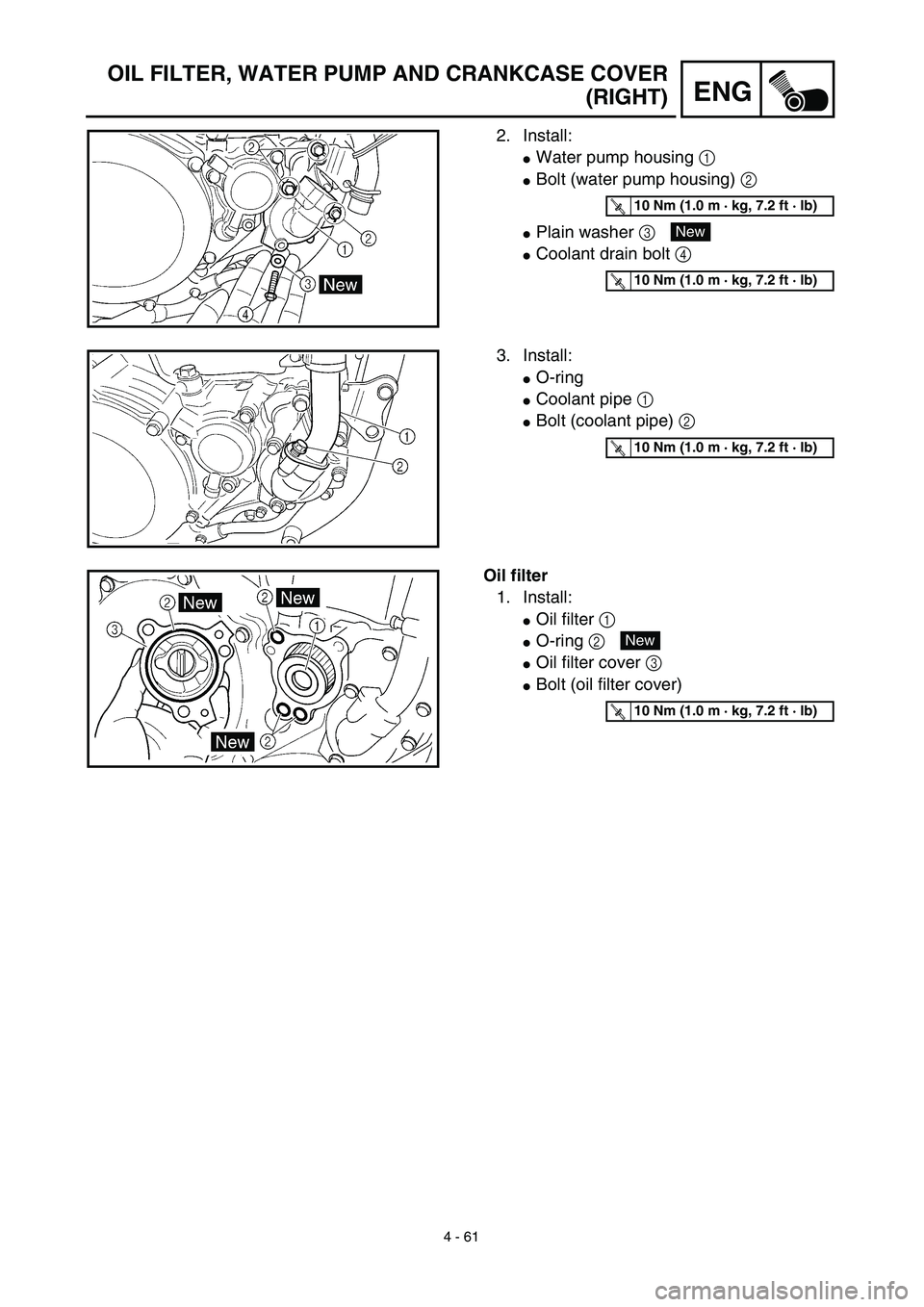
2. Install:
�Water pump housing 1
�Bolt (water pump housing) 2
�Plain washer 3
�Coolant drain bolt 4
T R..10 Nm (1.0 m · kg, 7.2 ft · lb)
New
T R..10 Nm (1.0 m · kg, 7.2 ft · lb)
3. Install:
�O-ring
�Coolant pipe 1
�Bolt (coolant pipe) 2
T R..10 Nm (1.0 m · kg, 7.2 ft · lb)
Oil filter
1. Install:
�Oil filter 1
�O-ring 2
�Oil filter cover 3
�Bolt (oil filter cover)
New
T R..10 Nm (1.0 m · kg, 7.2 ft · lb)
Page 460 of 644
5 - 10
CHASFRONT BRAKE AND REAR BRAKE
EC5A0000
FRONT BRAKE AND REAR BRAKE
EC5A8000
FRONT BRAKE
Extent of removal:1 Brake hose removal2 Caliper removal
3 Master cylinder removal
Extent of removal Order Part name Q’ty Remarks
Preparation for removalFRONT BRAKE REMOVAL
Hold the machine by placing the
suitable stand under the engine.
Drain the brake fluid.
WARNING
Support the machine securely so there is nodanger of it falling over.
Refer to “REMOVAL POINTS”.
1 Hose cover 1
2 Brake hose holder 1
3 Bolt (brake hose holder) 2 Only loosening.
4 Union bolt 2
5 Brake hose 1
6 Pad pin plug 1 Remove when loosening the pad pin.
7 Pad pin 1 Loosen when disassembling the caliper.
8 Caliper 1
9 Brake lever 1
10 Master cylinder bracket 1
11 Master cylinder 1
2
3
1
3
2
Page 462 of 644
5 - 11
CHAS
EC5A8100
REAR BRAKE
Extent of removal:1 Master cylinder removal2 Brake hose removal
3 Caliper removal
Extent of removal Order Part name Q’ty Remarks
Preparation for removalREAR BRAKE REMOVAL
Hold the machine by placing the
suitable stand under the engine.
WARNING
Support the machine securely so there is nodanger of it falling over.
Rear wheel Refer to “FRONT WHEEL AND REAR
WHEEL” section.
Drain the brake fluid. Refer to “REMOVAL POINTS”.
1 Brake pedal 1
2 Master cylinder 1
3 Brake hose holder 2
4 Union bolt 2
5 Brake hose 1
6 Pad pin plug 1 Remove when loosening the pad pin.
7 Pad pin 1 Loosen when disassembling the caliper.
8Caliper
1
3
1
321
FRONT BRAKE AND REAR BRAKE
Page 494 of 644
5 - 27
CHASFRONT FORK
EC558000
FRONT FORK DISASSEMBLY
Extent of removal:1 Oil seal removal2 Damper rod removal
Extent of removal Order Part name Q’ty Remarks
FRONT FORK DISASSEMBLY
1 Cap bolt 1 Refer to “REMOVAL POINTS”.
2 Fork spring 1 Drain the fork oil.
3 Dust seal 1
Refer to “REMOVAL POINTS”. 4 Stopper ring 1
5 Inner tube 1
6 Outer tube 1
7 Piston metal 1
8 Slide metal 1
9 Plain washer 1
0 Oil seal 1
A Spring guide 1
B Base valve 1 Use special tool.
C Damper rod 1 Refer to “REMOVAL POINTS”.
1
2