Page 368 of 644
4 - 62
ENGBALANCER
BALANCER
BALANCER
Extent of removal:1 Balancer drive gear2 Balancer
Extent of removal Order Part name Q’ty Remarks
BALANCER REMOVAL
Preparation for removal Clutch housing Refer to “CLUTCH” section.
Crankcase cover (right)Refer to “OIL FILTER, WATER PUMP AND
CRANKCASE COVER (RIGHT)” section.
Stator Refer to “CDI MAGNETO” section.
1 Nut (primary drive gear) 1
Refer to “REMOVAL POINTS”.
2 Nut (balancer) 1
3 Lock washer 1
4 Primary drive gear 1
5 Balancer drive gear 1
6 Lock washer 1
7 Balancer driven gear 1
8 Balancer 1 Refer to “REMOVAL POINTS”.
2
1
2
Page 374 of 644
4 - 65
ENGOIL PUMP
OIL PUMP
OIL PUMP
Extent of removal:1 Oil pump removal2 Oil pump disassembly
Extent of removal Order Part name Q’ty Remarks
OIL PUMP REMOVAL AND DIS-
ASSEMBLY
Preparation for removal Clutch housing Refer to “CLUTCH” section.
Crankcase cover (right)Refer to “OIL FILTER, WATER PUMP AND
CRANKCASE COVER (RIGHT)” section.
1 Circlip 1
2 Plate washer 1
3 Oil pump drive gear 1
4 Oil pump assembly 1
5 Dowel pin 1
6 Outer rotor 2 1
7 Circlip 1
8 Inner rotor 2 1
9 Pin 1
10 Oil pump cover 1
11 Outer rotor 1 1
12Inner rotor 1
1
2
1
Page 376 of 644
4 - 66
ENGOIL PUMP
Extent of removal Order Part name Q’ty Remarks
13 Pin 1
14 Washer 1
15 Oil pump drive shaft 1
16 Rotor housing 1
2
Page 378 of 644
4 - 67
ENGOIL PUMP
INSPECTION
Oil pump
1. Inspect:
�Oil pump drive gear
�Oil pump driven gear
�Rotor housing
�Oil pump cover
Cracks/wear/damage → Replace.
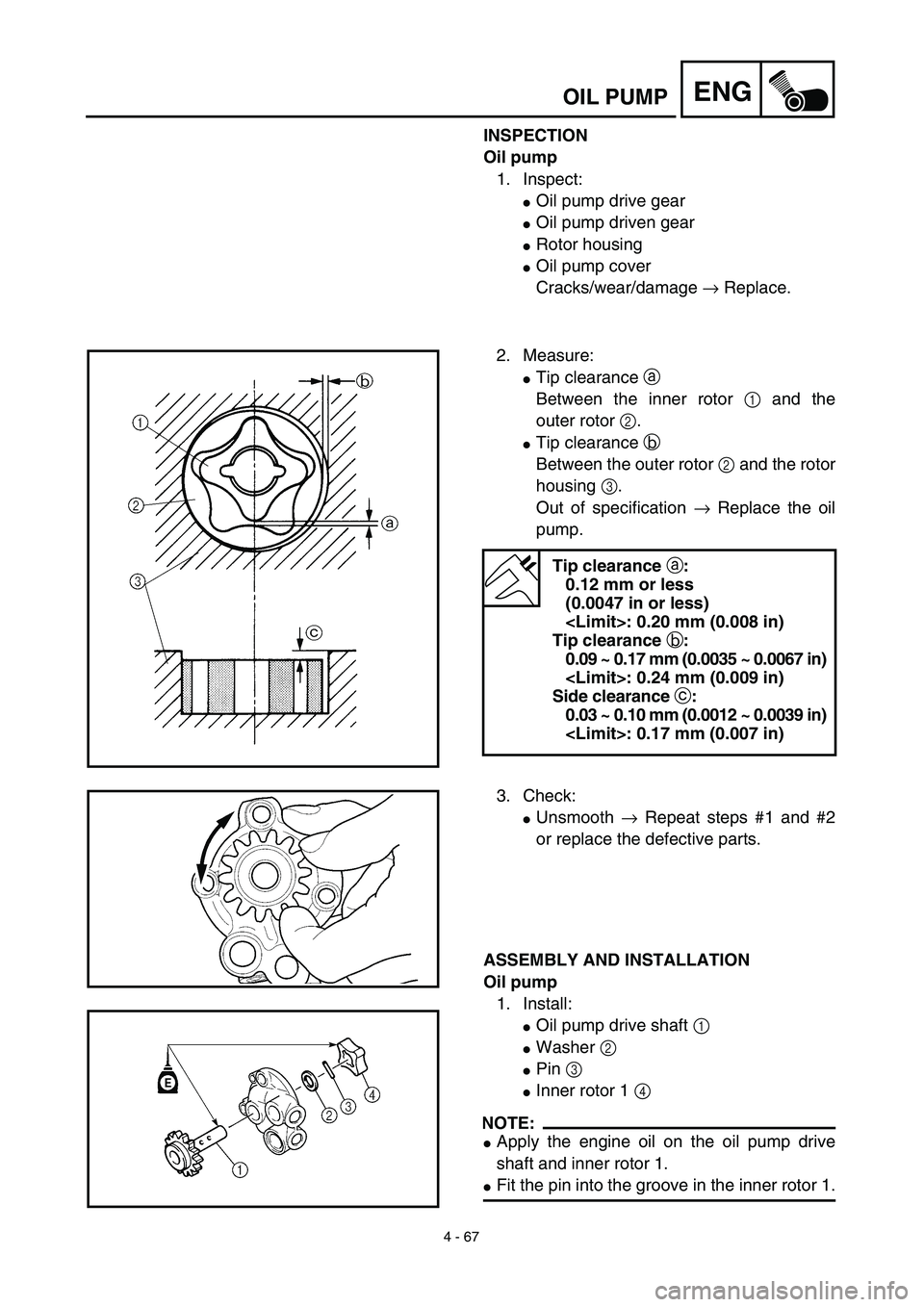
2. Measure:
�Tip clearance a
Between the inner rotor 1 and the
outer rotor 2.
�Tip clearance b
Between the outer rotor 2 and the rotor
housing 3.
Out of specification → Replace the oil
pump.
Tip clearance a:
0.12 mm or less
(0.0047 in or less)
: 0.20 mm (0.008 in)
Tip clearance b:
0.09 ~ 0.17 mm (0.0035 ~ 0.0067 in)
: 0.24 mm (0.009 in)
Side clearance c:
0.03 ~ 0.10 mm (0.0012 ~ 0.0039 in)
: 0.17 mm (0.007 in)
3. Check:
�Unsmooth → Repeat steps #1 and #2
or replace the defective parts.
ASSEMBLY AND INSTALLATION
Oil pump
1. Install:
�Oil pump drive shaft 1
�Washer 2
�Pin 3
�Inner rotor 1 4
NOTE:
�Apply the engine oil on the oil pump drive
shaft and inner rotor 1.
�Fit the pin into the groove in the inner rotor 1.
Page 380 of 644
4 - 68
ENGOIL PUMP
2. Install:
�Outer rotor 1 1
NOTE:
Apply the engine oil on the outer rotor 1.
3. Install:
�Oil pump cover 1
�Screw (oil pump cover) 2
�Pin 3
�Inner rotor 2 4
�Circlip 5
NOTE:
�Apply the engine oil on the oil pump drive
shaft end and inner rotor 2.
�Fit the pin into the groove in the inner rotor 2.
4. Install:
�Outer rotor 2 1
�Dowel pin 2
�Oil pump assembly 3
�Bolt (oil pump assembly)
[L = 30 mm (1.18 in)] 4
�Bolt (oil pump assembly)
[L = 25 mm (0.98 in)] 5
NOTE:
Apply the engine oil on the outer rotor 2.
T R..2 Nm (0.2 m · kg, 1.4 ft · lb)
New
T R..10 Nm (1.0 m · kg, 7.2 ft · lb)
T R..10 Nm (1.0 m · kg, 7.2 ft · lb)
5. Install:
�Oil pump drive gear 1
�Plate washer 2
�Circlip 3
NOTE:
Apply the engine oil on the oil pump drive gear
inner circumference.
New
Page 382 of 644
4 - 69
ENGKICK AXLE AND SHIFT SHAFT
KICK AXLE AND SHIFT SHAFT
KICK AXLE AND SHIFT SHAFT
Extent of removal:1 Kick axle removal2 Kick axle disassembly
3 Shift shaft removal4 Segment removal
Extent of removal Order Part name Q’ty Remarks
KICK AXLE AND SHIFT SHAFT
REMOVAL
Preparation for removal Oil pump Refer to “OIL PUMP” section.
1 Kick idle gear 1
2 Kick axle assembly 1 Refer to “REMOVAL POINTS”.
3 Spring guide 1
4 Torsion spring 1
5 Ratchet wheel 1
6 Kick gear 1
7 Kick axle 1
8 Plain washer 1
9 Shift pedal 1
10 Shift shaft 1
11 Collar 1
12 Torsion spring 1
3
2
1
4
1
Page 390 of 644
4 - 73
ENGKICK AXLE AND SHIFT SHAFT
EC4B5111
Stopper lever
1. Install:
�Torsion spring 1
�Stopper lever 2
�Bolt (stopper lever) 3
NOTE:
Align the stopper lever roller with the slot on
segment.
Shift guide and shift lever assembly
1. Install:
�Spring 1
�Pawl pin 2
�Pawl 3
To shift lever 4.
NOTE:
Apply the engine oil on the springs, pawl pins
and pawls.
2. Install:
�Shift lever assembly 1
To shift guide 2.
T R..10 Nm (1.0 m · kg, 7.2 ft · lb)
2
1
3. Install:
�Shift lever assembly 1
�Shift guide 2
NOTE:
�The shift lever assembly is installed at the
same time as the shift guide.
�Apply the engine oil on the bolt (segment)
shaft.
4. Install:
�Bolt (shift guide) 1
T R..10 Nm (1.0 m · kg, 7.2 ft · lb)
Page 392 of 644
4 - 74
ENGKICK AXLE AND SHIFT SHAFT
EC4C5301
Shift shaft
1. Install:
�Roller 1
�Collar 2
�Torsion spring 3
�Shift shaft 4
NOTE:
Apply the engine oil on the roller and shift
shaft.
2. Install:
�Shift pedal 1
�Bolt (shift pedal)
NOTE:
When installing the shift pedal onto the shift shaft,
be sure that the center of the shift pedal is about
2 mm (0.08 in) a above the top of the footrest.
T R..12 Nm (1.2 m · kg, 8.7 ft · lb)
Kick axle assembly
1. Install:
�Kick gear 1
�Plain washer 2
�Circlip 3
�Ratchet wheel 4
�Spring 5
�Plain washer 6
�Circlip 7
To kick axle 8.
NOTE:
�Apply the molybdenum disulfide oil on the
inner circumferences of the kick gear and
ratchet wheel.
�Align the punch mark a on the ratchet wheel
with the punch mark b on the kick axle.
New
New
2. Install:
�Torsion spring 1
To kick axle 2.
NOTE:
Make sure the stopper a of the torsion spring
fits into the hole b on the kick axle.