Page 378 of 644
4 - 67
ENGOIL PUMP
INSPECTION
Oil pump
1. Inspect:
�Oil pump drive gear
�Oil pump driven gear
�Rotor housing
�Oil pump cover
Cracks/wear/damage → Replace.
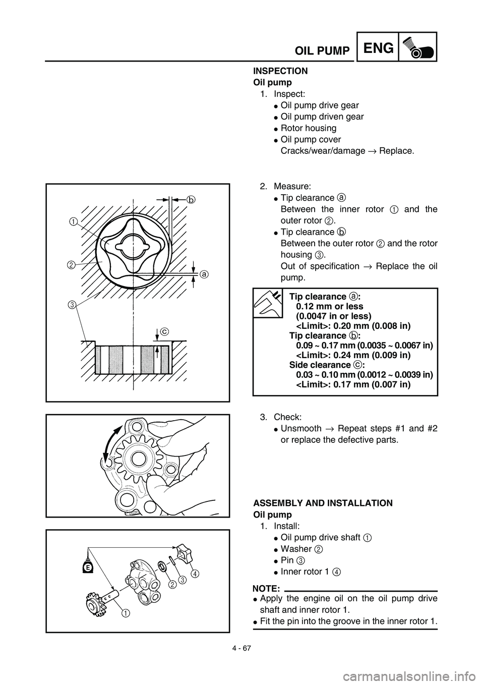
2. Measure:
�Tip clearance a
Between the inner rotor 1 and the
outer rotor 2.
�Tip clearance b
Between the outer rotor 2 and the rotor
housing 3.
Out of specification → Replace the oil
pump.
Tip clearance a:
0.12 mm or less
(0.0047 in or less)
: 0.20 mm (0.008 in)
Tip clearance b:
0.09 ~ 0.17 mm (0.0035 ~ 0.0067 in)
: 0.24 mm (0.009 in)
Side clearance c:
0.03 ~ 0.10 mm (0.0012 ~ 0.0039 in)
: 0.17 mm (0.007 in)
3. Check:
�Unsmooth → Repeat steps #1 and #2
or replace the defective parts.
ASSEMBLY AND INSTALLATION
Oil pump
1. Install:
�Oil pump drive shaft 1
�Washer 2
�Pin 3
�Inner rotor 1 4
NOTE:
�Apply the engine oil on the oil pump drive
shaft and inner rotor 1.
�Fit the pin into the groove in the inner rotor 1.
Page 428 of 644
4 - 92
ENGCRANKCASE AND CRANKSHAFT
NOTE:
�Hold the connecting rod at top dead center
with one hand while turning the nut of the
installing tool with the other. Operate the
installing tool until the crankshaft bottoms
against the bearing.
�Before installing the crankshaft, clean the
contacting surface of crankcase.
CAUTION:
Do not use a hammer to drive in the crank-
shaft.
2. Check:
�Shifter operation
�Transmission operation
Unsmooth operation → Repair.
3. Install:
�Oil strainer 1
�Bolt (oil strainer) 2
4. Apply:
�Sealant
On the crankcase (right) 1.
NOTE:
Clean the contacting surface of crankcase (left
and right) before applying the sealant.
Quick gasket®:
ACC-QUICK-GS-KT
YAMAHA Bond No. 1215:
90890-85505
T R..10 Nm (1.0 m · kg, 7.2 ft · lb)
Page 430 of 644
 4 - 93
ENGCRANKCASE AND CRANKSHAFT
5. Install:
�Dowel pin 1
�O-ring 2
�Crankcase (right)
To crankcase (left).
NOTE:
�Fit the crankcase (right) onto the crankcase
(left). Tap lightly on the case with")
4 - 93
ENGCRANKCASE AND CRANKSHAFT
5. Install:
�Dowel pin 1
�O-ring 2
�Crankcase (right)
To crankcase (left).
NOTE:
�Fit the crankcase (right) onto the crankcase
(left). Tap lightly on the case with soft ham-
mer.
�When installing the crankcase, the connect-
ing rod should be positioned at TDC (top
dead center).
New
6. Tighten:
�Hose guide 1
�Clutch cable holder 2
�Bolt (clutch cable holder)
�Bolt (crankcase)
NOTE:
Tighten the crankcase tightening bolts in
stage, using a crisscross pattern.
7. Install:
�Oil delivery pipe
�O-ring
�Bolt (oil delivery pipe)
8. Install:
�Timing chain
�Timing chain guide (rear)
�Bolt (timing chain guide)
9. Remove:
�Sealant
Forced out on the cylinder mating surface.
10. Apply:
�Engine oil
To the crank pin, bearing and oil deliv-
ery hole.
11. Check:
�Crankshaft and transmission operation.
Unsmooth operation → Repair.
T R..10 Nm (1.0 m · kg, 7.2 ft · lb)
T R..12 Nm (1.2 m · kg, 8.7 ft · lb)
New
T R..10 Nm (1.0 m · kg, 7.2 ft · lb)
T R..10 Nm (1.0 m · kg, 7.2 ft · lb)
Page 436 of 644
4 - 96
ENGTRANSMISSION, SHIFT CAM AND SHIFT FORK
EC4H4801
Shift fork, shift cam and segment
1. Inspect:
�Shift fork 1
Wear/damage/scratches → Replace.
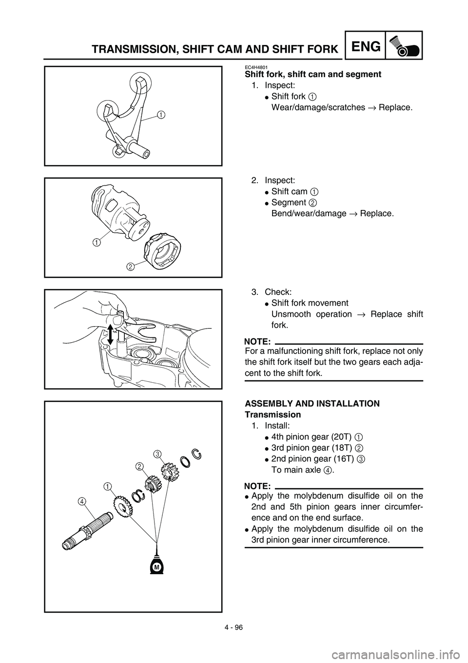
2. Inspect:
�Shift cam 1
�Segment 2
Bend/wear/damage → Replace.
3. Check:
�Shift fork movement
Unsmooth operation → Replace shift
fork.
NOTE:
For a malfunctioning shift fork, replace not only
the shift fork itself but the two gears each adja-
cent to the shift fork.
ASSEMBLY AND INSTALLATION
Transmission
1. Install:
�4th pinion gear (20T) 1
�3rd pinion gear (18T) 2
�2nd pinion gear (16T) 3
To main axle 4.
NOTE:
�Apply the molybdenum disulfide oil on the
2nd and 5th pinion gears inner circumfer-
ence and on the end surface.
�Apply the molybdenum disulfide oil on the
3rd pinion gear inner circumference.
Page 440 of 644
4 - 98
ENGTRANSMISSION, SHIFT CAM AND SHIFT FORK
5. Install:
�Shift fork 1 (L) 1
�Shift fork 2 (R) 2
�Shift cam 3
To main axle and drive axle.
NOTE:
�Apply the molybdenum disulfide oil on the
shift fork grooves.
�Mesh the shift fork #1 (L) with the 3rd pinion
gear 4 on the main axle.
�Mesh the shift fork #2 (R) with the 4th wheel
gear 5 on the drive axle.
6. Install:
�Transmission assembly 1
To crankcase (left) 2.
NOTE:
Apply the engine oil on the bearings and guide
bars.
7. Check:
�Shifter operation
�Transmission operation
Unsmooth operation → Repair.
Page 508 of 644
5 - 34
CHASFRONT FORK
13. Check:
�Inner tube smooth movement
Tightness/binding/rough spots →
Repeat the steps 2 to 12.
14. Compress the front fork fully.
15. Fill:
�Front fork oil
Until outer tube top surface with recom-
mended fork oil 1.
ACHTUNG:CAUTION:
�Be sure to use recommended fork oil. If
other oils are used, they may have an
excessively adverse effect on the front
fork performance.
�Never allow foreign materials to enter the
front fork.
Recommended oil:
Suspension oil “01”
16. After filling, pump the damper rod 1
slowly up and down more than 10 times
to distribute the fork oil.
17. Fill:
�Front fork oil
Until outer tube top surface with recom-
mended fork oil once more.
18. After filling, pump the outer tube 1 slowly
up and down (about 200 mm (7.9 in)
stroke) to distribute the fork oil once
more.
NOTE:
Be careful not to excessive full stroke. A stroke
of 200 mm (7.9 in) or more will cause air to
enter. In this case, repeat the steps 15 to 18.
Page 510 of 644
 5 - 35
CHASFRONT FORK
19. Wait ten minutes until the air bubbles
have been removed from the front fork,
and the oil has dispense evenly in system
before setting recommended oil level.
NOTE:
Fill with")
5 - 35
CHASFRONT FORK
19. Wait ten minutes until the air bubbles
have been removed from the front fork,
and the oil has dispense evenly in system
before setting recommended oil level.
NOTE:
Fill with the fork oil up to the top end of the
outer tube, or the fork oil will not spread over to
every part of the front forks, thus making it
impossible to obtain the correct level.
Be sure to fill with the fork oil up to the top of
the outer tube and bleed the front forks.
20. Measure:
�Oil level (left and right) a
Out of specification → Adjust.
NOTE:
Be sure to install the spring guide 2 when
checking the oil level.
WARNING
Never fail to make the oil level adjustment
between the maximum and minimum level
and always adjust each front fork to the
same setting. Uneven adjustment can
cause poor handling and loss of stability.
Standard oil level:
135 mm (5.31 in)
Extent of adjustment:
80 ~ 150 mm (3.15 ~ 5.91 in)
From top of outer tube with
inner tube and damper rod 1
fully compressed without
spring.
Page 550 of 644
5 - 55
CHASSWINGARM
3. Install:
�Collar 1
To connecting rod 2.
NOTE:
Apply the molybdenum disulfide grease on the
collar and oil seal lips.
4. Install:
�Connecting rod 1
�Bolt (connecting rod) 2
�Plain washer 3
�Nut (connecting rod) 4
To relay arm 5.
NOTE:
Apply the molybdenum disulfide grease on the
bolt.
T R..80 Nm (8.0 m · kg, 58 ft · lb)
5. Install:
�Relay arm 1
�Bolt (relay arm) 2
�Plain washer 3
�Nut (relay arm) 4
To swingarm.
NOTE:
�Apply the molybdenum disulfide grease on
the bolt.
�Do not tighten the nut yet.
6. Install:
�Swingarm 1
�Pivot shaft 2
NOTE:
�Apply the molybdenum disulfide grease on
the pivot shaft.
�Insert the pivot shaft from right side.
T R..85 Nm (8.5 m · kg, 61 ft · lb)
7. Check:
�Swingarm side play a
Free play exists → Replace thrust bear-
ing.
�Swingarm up and down movement b
Unsmooth movement/binding/rough
spots → Grease or replace bearings,
bushes and collars.