Page 488 of 644
 5 - 24
CHASFRONT BRAKE AND REAR BRAKE
2. Install:
�Brake hose holder 1
�Screw (brake hose holder) 2
ACHTUNG:CAUTION:
After installing the brake hose holders,
make sure the brake hose does not contac")
5 - 24
CHASFRONT BRAKE AND REAR BRAKE
2. Install:
�Brake hose holder 1
�Screw (brake hose holder) 2
ACHTUNG:CAUTION:
After installing the brake hose holders,
make sure the brake hose does not contact
the spring (rear shock absorber). If it does,
correct its twist.
T R..1 Nm (0.1 m · kg, 0.7 ft · lb)
Brake fluid
1. Fill:
�Brake fluid
Until the fluid level reaches “LOWER”
level line a.
WARNING
�Use only the designated quality brake
fluid:
otherwise, the rubber seals may deterio-
rate, causing leakage and poor brake per-
formance.
�Refill with the same type of brake fluid;
mixing fluids may result in a harmful chem-
ical reaction and lead to poor performance.
�Be careful that water does not enter the
master cylinder when refilling. Water will
significantly lower the boiling point of the
fluid and may result in vapor lock.
ACHTUNG:CAUTION:
Brake fluid may erode painted surfaces or
plastic parts. Always clean up spilled fluid
immediately.
ÅFront
ıRear
Recommended brake fluid:
DOT #4
Å
ı
Page 513 of 644
 5 - 36
CHAS
FOURCHE AVANT
TELESKOPGABEL
21. Messen:
�Gewindelänge a
Unvorschriftsmäßig → Die Sicherungs-
mutter hineindrehen.
22. Herausdrehen:
�Zugstufendämpfungs-Einstellschraube
1
HINWEIS:")
5 - 36
CHAS
FOURCHE AVANT
TELESKOPGABEL
21. Messen:
�Gewindelänge a
Unvorschriftsmäßig → Die Sicherungs-
mutter hineindrehen.
22. Herausdrehen:
�Zugstufendämpfungs-Einstellschraube
1
HINWEIS:
�Die Zugstufendämpfungs-Einstellschraube
bis zum Anschlag herausdrehen.
�Die Einstellung (Anzahl Rasten nach völligem
Hineindrehen) aufschreiben.
23. Montieren:
�Dämpfergummi 1
�Scheibe 2
�Distanzstück 3
(an Verschlußschraube 4)
HINWEIS:
Das Dämpfergummi mit dem kleineren Ende
a zur Verschlußschraube einbauen.
Gewindelänge a
(Abstand zwischen der Oberkante
des Dämpferrohrs 1 und der
Oberkante der Sicherungsmutter
2)
min. 20 mm
21. Mesurer:
�Distance a
Hors spécification → Serrer le contre-
écrou.
Distance a:
20 mm (0,79 in) ou plus
Entre le haut de la tige d’amortisseur
1 et le haut du contre-écrou 2.
24. Montieren:
�Druckstange 1
�Gabelfeder 2
HINWEIS:
�Die Gabelfeder mit gehobenem Dämpferrohr
3 einbauen.
�Nach dem Einbau der Gabelfeder das
Dämpferrohr festhalten, damit es nicht her-
abfällt.
25. Montieren:
�Verschlußschraube 1
Die Verschlußschraube handfest auf
das Dämpferrohr schrauben. 22. Desserrer:
�Dispositif de réglage de l’amortissement de
détente 1
N.B.:
�Desserrer à la main le dispositif de réglage de
l’amortissement de détente et de compression.
�Noter la position réglée du dispositif de réglage
de l’amortissement de détente (le nombre de
tours à partir de la position vissée à fond).
23. Monter:
�Garniture en caoutchouc 1
�Rondelle 2
�Entretoise 3
Au bouchon de fourche 4.
N.B.:
Installer la garniture en caoutchouc avec le côté de
plus faible diamètre a face au bouchon de fourche.
24. Monter:
�Tige de poussée 1
�Ressort de fourche 2
N.B.:
�Installer le ressort de fourche avec la tige d’amor-
tisseur 3 déployée.
�Après avoir installé le ressort de fourche, mainte-
nir la tige d’amortisseur de façon à ce qu’elle ne
redescende pas.
25. Monter:
�Bouchon de fourche 1
Serrer à fond manuellement le bouchon de
fourche sur la tige d’amortisseur.
Page 540 of 644
5 - 50
CHASSWINGARM
EC570000
SWINGARM
Extent of removal:1 Swingarm removal
Extent of removal Order Part name Q’ty Remarks
SWINGARM REMOVAL
WARNING
Support the machine securely so there is no
danger of it falling over.
Preparation for removal Hold the machine by placing the
suitable stand under the engine.
Brake hose holder
Rear caliper
Bolt (brake pedal)
Drive chainRefer to “FRONT BRAKE AND REAR
BRAKE” section.
Shift the brake pedal backward.
1 Chain support 1
2 Chain tensioner (lower) 1
3 Bolt (rear shock absorber-relay
arm)1 Hold the swingarm.
4 Bolt (connecting rod) 1
5 Pivot shaft 1
6 Swingarm 1
1
Page 552 of 644
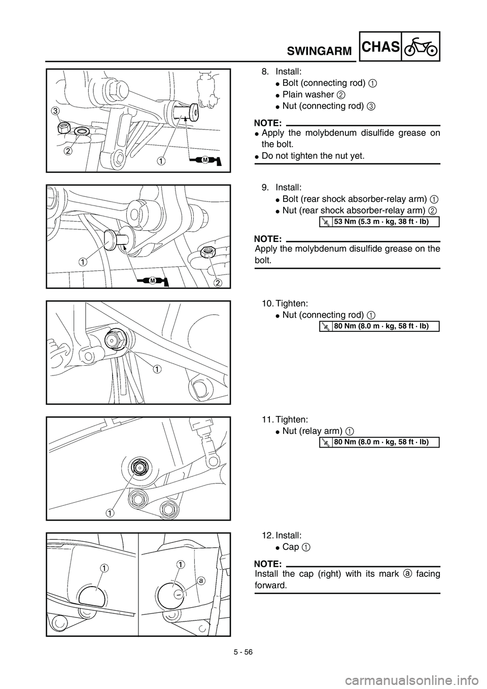
5 - 56
CHASSWINGARM
8. Install:
�Bolt (connecting rod) 1
�Plain washer 2
�Nut (connecting rod) 3
NOTE:
�Apply the molybdenum disulfide grease on
the bolt.
�Do not tighten the nut yet.
9. Install:
�Bolt (rear shock absorber-relay arm) 1
�Nut (rear shock absorber-relay arm) 2
NOTE:
Apply the molybdenum disulfide grease on the
bolt.
T R..53 Nm (5.3 m · kg, 38 ft · lb)
10. Tighten:
�Nut (connecting rod) 1
T R..80 Nm (8.0 m · kg, 58 ft · lb)
11. Tighten:
�Nut (relay arm) 1
T R..80 Nm (8.0 m · kg, 58 ft · lb)
12. Install:
�Cap 1
NOTE:
Install the cap (right) with its mark a facing
forward.
Page 556 of 644
5 - 58
CHASREAR SHOCK ABSORBER
EC580000
REAR SHOCK ABSORBER
Extent of removal:1 Rear shock absorber removal2 Rear shock absorber disassembly
Extent of removal Order Part name Q’ty Remarks
Preparation for removalREAR SHOCK ABSORBER
REMOVAL
Hold the machine by placing the
suitable stand under the engine.
WARNING
Support the machine securely so there is nodanger of it falling over.
Seat and fitting band Refer to “SEAT, FUEL TANK AND SIDE
COVERS” section in the CHAPTER 4.
Silencer Refer to “EXHAUST PIPE AND
SILENCER” section in the CHAPTER 4.
1 Clamp (air filter joint) 1 Only loosening.
2 Rear frame 1
3 Bolt (rear shock absorber-relay
arm)1 Hold the swingarm.
4 Bolt (rear shock absorber-frame) 1
5 Rear shock absorber 1
6 Locknut 1 Only loosening.
7 Adjuster 1 Only loosening.
8 Spring guide (lower) 1
1
2
Page 558 of 644
5 - 59
CHASREAR SHOCK ABSORBER
Extent of removal Order Part name Q’ty Remarks
9 Spring guide (upper) 1
10 Spring (rear shock absorber) 1
11 Bearing 2 Refer to “REMOVAL POINTS”.
2
Page 560 of 644
 5 - 60
CHAS
EC586000
HANDLING NOTE
WARNING
This shock absorber is provided with a
separate type tank filled with high-pressure
nitrogen gas. To prevent the danger of
explosion, read and understand the")
5 - 60
CHAS
EC586000
HANDLING NOTE
WARNING
This shock absorber is provided with a
separate type tank filled with high-pressure
nitrogen gas. To prevent the danger of
explosion, read and understand the follow-
ing information before handling the shock
absorber.
The manufacturer can not be held respon-
sible for property damage or personal
injury that may result from improper han-
dling.
1. Never tamper or attempt to disassem-
ble the cylinder or the tank.
2. Never throw the shock absorber into
an open flame or other high heat. The
shock absorber may explode as a
result of nitrogen gas expansion and/
or damage to the hose.
3. Be careful not to damage any part of
the gas tank. A damaged gas tank will
impair the damping performance or
cause a malfunction.
4. Take care not to scratch the contact
surface of the piston rod with the cylin-
der; or oil could leak out.
5. Never attempt to remove the plug at
the bottom of the nitrogen gas tank. It
is very dangerous to remove the plug.
6. When scrapping the shock absorber,
follow the instructions on disposal.
EC587000
NOTES ON DISPOSAL (YAMAHA DEALERS
ONLY)
Before disposing the shock absorber, be sure
to extract the nitrogen gas from valve 1. Wear
eye protection to prevent eye damage from
escaping gas and/or metal chips.
WARNING
To dispose of a damaged or worn-out
shock absorber, take the unit to your
Yamaha dealer for this disposal procedure.
REAR SHOCK ABSORBER
Page 562 of 644
5 - 61
CHAS
EC583000
REMOVAL POINTS
EC583320
Bearing
1. Remove:
�Stopper ring (upper bearing) 1
NOTE:
Press in the bearing while pressing its outer
race and remove the stopper ring.
2. Remove:
�Upper bearing 1
NOTE:
Remove the bearing by pressing its outer race.
3. Remove:
�Lower bearing 1
NOTE:
Remove the bearing by pressing its outer race.
EC584000
INSPECTION
Rear shock absorber
1. Inspect:
�Damper rod 1
Bends/damage → Replace absorber
assembly.
�Shock absorber 2
Oil leaks → Replace absorber assem-
bly.
Gas leaks → Replace absorber assem-
bly.
�Spring 3
Damage → Replace spring.
Fatigue → Replace spring.
Move spring up and down.
�Spring guide 4
Wear/damage → Replace spring guide.
�Bearing 5
Free play exists/unsmooth revolution/
rust → Replace.
REAR SHOCK ABSORBER
 5 - 50
CHASSWINGARM
EC570000
SWINGARM
Extent of removal:1 Swingarm removal
Extent of removal Order Part name Q’ty Remarks
SWINGARM REMOVAL
WARNING
Support the machine securely so there is no
danger")
 5 - 58
CHASREAR SHOCK ABSORBER
EC580000
REAR SHOCK ABSORBER
Extent of removal:1 Rear shock absorber removal2 Rear shock absorber disassembly
Extent of removal Order Part name Q’ty Remarks
Preparatio")
 5 - 59
CHASREAR SHOCK ABSORBER
Extent of removal Order Part name Q’ty Remarks
9 Spring guide (upper) 1
10 Spring (rear shock absorber) 1
11 Bearing 2 Refer to “REMOVAL POINTS”.
2")
