Page 378 of 644
4 - 67
ENGOIL PUMP
INSPECTION
Oil pump
1. Inspect:
�Oil pump drive gear
�Oil pump driven gear
�Rotor housing
�Oil pump cover
Cracks/wear/damage → Replace.
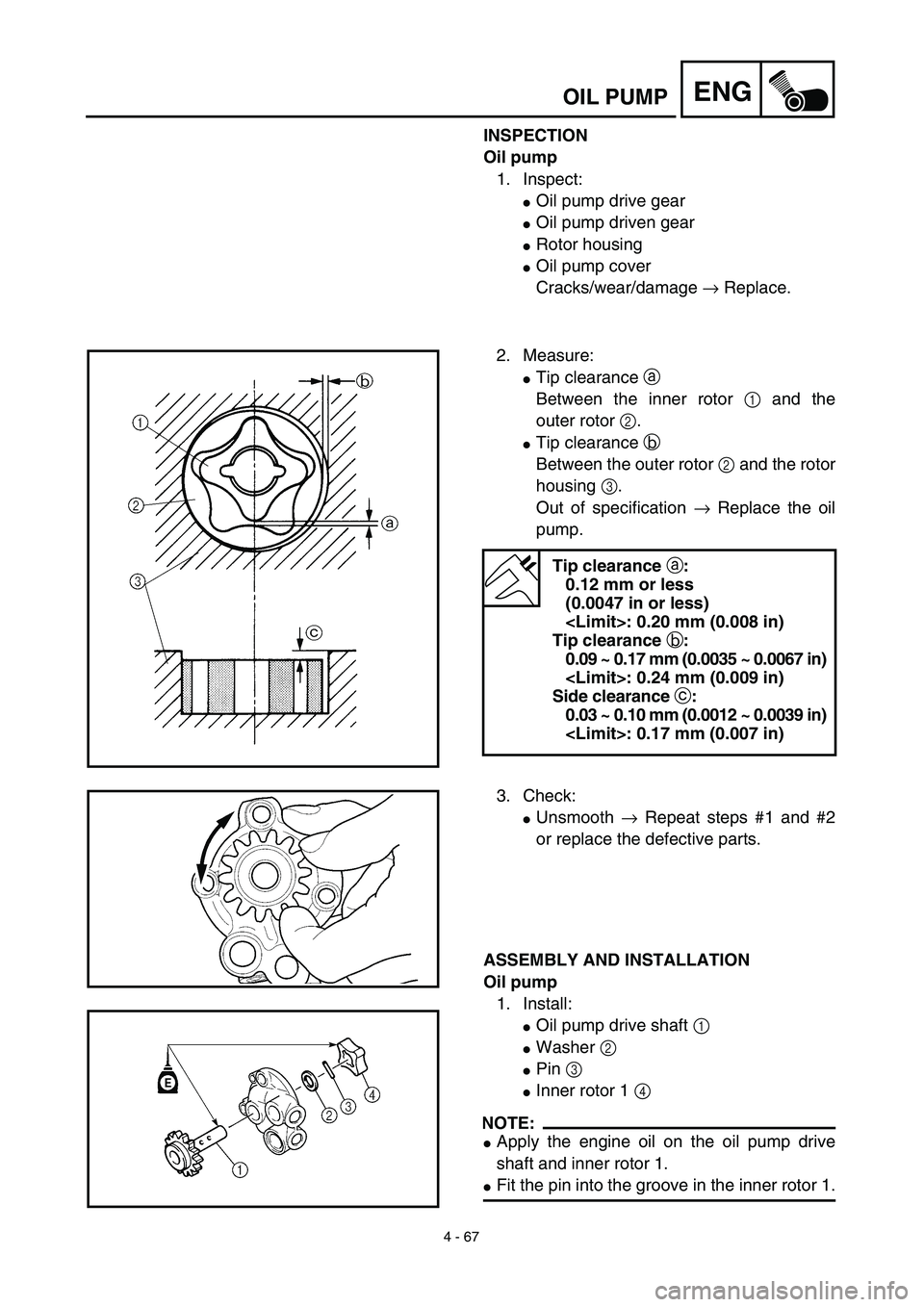
2. Measure:
�Tip clearance a
Between the inner rotor 1 and the
outer rotor 2.
�Tip clearance b
Between the outer rotor 2 and the rotor
housing 3.
Out of specification → Replace the oil
pump.
Tip clearance a:
0.12 mm or less
(0.0047 in or less)
: 0.20 mm (0.008 in)
Tip clearance b:
0.09 ~ 0.17 mm (0.0035 ~ 0.0067 in)
: 0.24 mm (0.009 in)
Side clearance c:
0.03 ~ 0.10 mm (0.0012 ~ 0.0039 in)
: 0.17 mm (0.007 in)
3. Check:
�Unsmooth → Repeat steps #1 and #2
or replace the defective parts.
ASSEMBLY AND INSTALLATION
Oil pump
1. Install:
�Oil pump drive shaft 1
�Washer 2
�Pin 3
�Inner rotor 1 4
NOTE:
�Apply the engine oil on the oil pump drive
shaft and inner rotor 1.
�Fit the pin into the groove in the inner rotor 1.
Page 420 of 644
 4 - 88
ENGCRANKCASE AND CRANKSHAFT
REMOVAL POINTS
Crankcase
1. Separate:
�Crankcase (right)
�Crankcase (left)
Separation steps:
�Remove the crankcase bolts, hose guide
and clutch cable holder.
NOTE:
L")
4 - 88
ENGCRANKCASE AND CRANKSHAFT
REMOVAL POINTS
Crankcase
1. Separate:
�Crankcase (right)
�Crankcase (left)
Separation steps:
�Remove the crankcase bolts, hose guide
and clutch cable holder.
NOTE:
Loosen each bolt 1/4 of a turn at a time and
after all the bolts are loosened, remove
them.
�Remove the crankcase (right).
NOTE:
�Place the crankcase with its left side
downward and split it by inserting a screw-
driver tip into the splitting slit a in the
crankcase.
�Lift the crankcase (right) horizontally while
lightly patting the case splitting slit and
engine mounting boss using a soft ham-
mer, and leave the crankshaft and trans-
mission with the crankcase (left).
CAUTION:
Use soft hammer to tap on the case half.
Tap only on reinforced portions of case.
Do not tap on gasket mating surface.
Work slowly and carefully. Make sure the
case halves separate evenly. If one end
“hangs up”, take pressure off the push
screw, realign, and start over. If the
cases do not separate, check for a
remaining case screw or fitting. Do not
force.
�Remove the dowel pins and O-ring.
a
Page 430 of 644
 4 - 93
ENGCRANKCASE AND CRANKSHAFT
5. Install:
�Dowel pin 1
�O-ring 2
�Crankcase (right)
To crankcase (left).
NOTE:
�Fit the crankcase (right) onto the crankcase
(left). Tap lightly on the case with")
4 - 93
ENGCRANKCASE AND CRANKSHAFT
5. Install:
�Dowel pin 1
�O-ring 2
�Crankcase (right)
To crankcase (left).
NOTE:
�Fit the crankcase (right) onto the crankcase
(left). Tap lightly on the case with soft ham-
mer.
�When installing the crankcase, the connect-
ing rod should be positioned at TDC (top
dead center).
New
6. Tighten:
�Hose guide 1
�Clutch cable holder 2
�Bolt (clutch cable holder)
�Bolt (crankcase)
NOTE:
Tighten the crankcase tightening bolts in
stage, using a crisscross pattern.
7. Install:
�Oil delivery pipe
�O-ring
�Bolt (oil delivery pipe)
8. Install:
�Timing chain
�Timing chain guide (rear)
�Bolt (timing chain guide)
9. Remove:
�Sealant
Forced out on the cylinder mating surface.
10. Apply:
�Engine oil
To the crank pin, bearing and oil deliv-
ery hole.
11. Check:
�Crankshaft and transmission operation.
Unsmooth operation → Repair.
T R..10 Nm (1.0 m · kg, 7.2 ft · lb)
T R..12 Nm (1.2 m · kg, 8.7 ft · lb)
New
T R..10 Nm (1.0 m · kg, 7.2 ft · lb)
T R..10 Nm (1.0 m · kg, 7.2 ft · lb)
Page 440 of 644
4 - 98
ENGTRANSMISSION, SHIFT CAM AND SHIFT FORK
5. Install:
�Shift fork 1 (L) 1
�Shift fork 2 (R) 2
�Shift cam 3
To main axle and drive axle.
NOTE:
�Apply the molybdenum disulfide oil on the
shift fork grooves.
�Mesh the shift fork #1 (L) with the 3rd pinion
gear 4 on the main axle.
�Mesh the shift fork #2 (R) with the 4th wheel
gear 5 on the drive axle.
6. Install:
�Transmission assembly 1
To crankcase (left) 2.
NOTE:
Apply the engine oil on the bearings and guide
bars.
7. Check:
�Shifter operation
�Transmission operation
Unsmooth operation → Repair.
Page 575 of 644
–+ELEC
6 - 3
IGNITION SYSTEM
EC620000
IGNITION SYSTEM
INSPECTION STEPS
Use the following steps for checking the possibility of the malfunctioning engine being attributable to
ignition system failure and for checking the spark plug which will not spark.
*marked: Only when the ignition checker is used.
NOTE:
�
Remove the following parts before inspection.
1) Seat
2) Fuel tank
�
Use the following special tools in this inspection.
Dynamic spark tester:
YM-34487
Ignition checker:
90890-06754
Pocket tester:
YU-3112-C/90890-03112
Spark gap test*Clean or replace
spark plug.
Check entire ignition
system for connection.
(couplers, leads and
ignition coil)Repair or replace.
Check “ENGINE STOP”
button.Replace.
Check ignition coil. Primary coil Replace.
Secondary coil Replace.
Check CDI magneto. Pick-up coil Replace.
Source coil Replace.
Check neutral switch. Repair or replace.
Replace CDI unit.
No spark
OK
OK
OK
OK
OK
Spark
No good
No good
No good
No good
No good
No good
No good
Page 578 of 644

6 - 4
–+ELEC
IGNITION SYSTEM
SPARK GAP TEST
1. Disconnect the ignition coil from spark
plug.
2. Remove the ignition coil cap.
3. Connect the dynamic spark tester
1
(ignition checker
2")
6 - 4
–+ELEC
IGNITION SYSTEM
SPARK GAP TEST
1. Disconnect the ignition coil from spark
plug.
2. Remove the ignition coil cap.
3. Connect the dynamic spark tester
1
(ignition checker
2
) as shown.
�
Ignition coil
3
�
Spark plug
4
Å
For USA and CDN
ı
Except for USA and CDN
4. Kick the kick starter.
5. Check the ignition spark gap.
6. Start engine, and increase spark gap until
misfire occurs. (for USA and CDN only)
Minimum spark gap:
6.0 mm (0.24 in)
Å
ı
COUPLERS, LEADS AND IGNITION COIL
CONNECTION INSPECTION
1. Check:
�
Couplers and leads connection
Rust/dust/looseness/short-circuit
→
Repair or replace.
�
Ignition coil and spark plug as they are
fitted
Push in the ignition coil until it closely
contacts the spark plug hole in the cyl-
inder head cover.
EC625001
“ENGINE STOP” BUTTON INSPECTION
1. Inspect:
�
“ENGINE STOP” button conduct
No continuity while being pushed
→
Replace.
Continuity while being freed
→
Replace.
Tester (+) lead
→
Black/White lead
1
Tester (–) lead
→
Black lead
2
B/W
1
B
2
Tester selec-
tor position
PUSH IN
Ω
×
1
FREE
B/W B
11 2 2
Page 584 of 644
–+ELEC
6 - 7
TPS (THROTTLE POSITION SENSOR) SYSTEM
EC690000
TPS (THROTTLE POSITION SENSOR) SYSTEM
INSPECTION STEPS
If the TPS will not operate, use the following inspection steps.
*marked: Refer to “IGNITION SYSTEM” section.
NOTE:
Use the following special tools in this inspection.
Pocket tester:
YU-3112-C/90890-03112Inductive tachometer:
YU-8036-B
Engine tachometer:
90890-03113
Check entire ignition
system for connection.Repair or replace.
Check TPS. TPS coil Replace.
*Check CDI magneto. Source coil Replace.
Check CDI unit.TPS input
voltageReplace.
OK
OK
OK
No good
No good
No good
No good
Page 588 of 644
6 - 8
–+ELECTPS (THROTTLE POSITION SENSOR) SYSTEM
HANDLING NOTE
CAUTION:
Do not loosen the screws {TPS (throttle
position sensor)} 1 except when changing
the TPS (throttle position sensor) due to
failure because it will cause a drop in
engine performance.
1
EC624000
COUPLERS AND LEADS CONNECTION
INSPECTION
1. Check:
�Couplers and leads connection
Rust/dust/looseness/short-circuit →
Repair or replace.
TPS COIL INSPECTION
1. Inspect:
�TPS coil resistance
Out of specification → Replace.
2. Loosen:
�Throttle stop screw 1
NOTE:
Turn out the throttle stop screw until the throt-
tle shaft is in the full close position.Tester (+) lead → Blue lead 1
Tester (–) lead → Black lead 2
TPS coil
resistanceTester selector
position
4 ~ 6 kΩ at
20 ˚C (68 ˚F)kΩ × 1

 –+ELEC
6 - 3
IGNITION SYSTEM
EC620000
IGNITION SYSTEM
INSPECTION STEPS
Use the following steps for checking the possibility of the malfunctioning engine being attributable to
ignition system")
 –+ELEC
6 - 7
TPS (THROTTLE POSITION SENSOR) SYSTEM
EC690000
TPS (THROTTLE POSITION SENSOR) SYSTEM
INSPECTION STEPS
If the TPS will not operate, use the following inspection steps.
*marked: Refer to")
 6 - 8
–+ELECTPS (THROTTLE POSITION SENSOR) SYSTEM
HANDLING NOTE
CAUTION:
Do not loosen the screws {TPS (throttle
position sensor)} 1 except when changing
the TPS (throttle position sensor) due to
fa")